InPOWER LVD20-100 User manual

© Copyright 2022 InPower LLC
LVD20 Series Owners Manual
Document: OM-230 Version Code: A
Date: May 6, 2019 Date: Mar 31, 2022
Page
1 of 4
InPower LLC
8311 Green Meadows Drive
Lewis Center, Ohio 43035 USA
740-548-0965
www.InPowerLLC.com
Introduction
The InPower LVD20 Series is a family of high current, low voltage disconnects. These disconnects are available in
current ratings of 100, 150 and 200 amps, and are packaged in a sealed metal case. As they have extremely low
current draw when in the off state, they are ideally suited for use as battery disconnect switches. A key feature is
the disconnect’s highly efcent, low on-resistance DC power switch. This results in superior performance by pro-
ducing a low voltage drop and generating only a small amount if internal heat.
A status LED indicator is illuminated when the disconnect is on, and ashes to indicate a fault shutdown condition.
Automatic fault shutdown is provided for over current, loss of ground and low battery voltage. Under a fault condi-
tion, the disconnect is latched in the off state. To reset the unit, the fault must be cleared, then the control input
voltage must be removed and then re-applied. Removing the battery cable will also reset the unit.
The control input utilizes a ¼ inch male faston blade terminal. Connections for the high current DC cables utilize
3/8” - 16 stainless steel threaded studs with brass contact pads for low contact resistance. The terminal design
allows the use of an optional rubber terminal protection boot for added protection from the environment, as well as
accidental shorting. Four mounting contact pads allow for the required connection to ground.
System Operation
When positive voltage is applied to the control terminal, the disconnect switch turns ON to pass through battery
power to its load output terminal. When the disconnect switch is on, its controller monitors the battery voltage at its
battery terminal. When the battery voltage drops below 11.5 volts for 60 seconds (factory programmable) the disconnect
switch turns off, removing power from the load terminal, and therefore removes the power draw on the battery.
When the battery is charging and the battery voltage exceeds the shut off preset voltage, the disconnect can be
manually re-actuated by removing the control input voltage and re-applying it (an automatic turn-on may be custom
programmed).
OWNERS MANUAL
Low Voltage Disconnect Models:
LVD20-100 (100 Amps)
LVD20-150 (150 Amps)
LVD20-200 (200 Amps)
InPower Low Voltage Disconnect
Ground
LOAD
Battery
+
+12 Volt Loads
Ground
+12 Volts
Control Switch
Ground
Solid State Contactor
LVD20-200
Lot#
Ground
Status LED
Controller
Control Input
Electronic Switch
LOAD
+BAT
Fuse

© Copyright 2022 InPower LLC
LVD20 Series Owners Manual
Document: OM-230 Version Code: A
Date: May 6, 2019 Date: Mar 31, 2022
Page
2 of 4
InPower LLC
8311 Green Meadows Drive
Lewis Center, Ohio 43035 USA
740-548-0965
www.InPowerLLC.com
The Low Voltage Disconnect is controlled by a positive DC voltage on its control terminal. The turnon voltage is >+9.5
Vdc. The must release voltage is <+8.5 Vdc. Note that the input voltage must drop to under +4.0 volts, then
increase to >+9.5 volts to turn on again.
Certain fault conditions will cause the power switch to turn off and remain latched off until the fault is cleared and the
control input voltage is removed, then re-applied. The status LED will ash to indicate a fault. These fault conditions
include:
1. An over-current condition for greater than 500 milliseconds.
2. Loss of ground
3. Low battery voltage
Specications
Current Rating: LVD20-100 LVD20-150 LVD20-200
Maximum current at 43º C (110º F)*
Type A Mounting** 100 Amps 150 Amps 200 Amps
Type B Mounting** 75 Amps 100 Amps 125 Amps
On-resistance at maximum current
and temperature: 2.2 milliohms 1.1 milliohms 0.75 milliohm
* Mounting surface temperature. Note - The maximum current rating will be derated above 43º C (110º F).
** Mounting surface types:
Type A - Mounting surface such as an aluminum plate 0.125 x 16 x 16 inches.
Type B - Mounting surface such as wood, plastic or free air
Mounting Environment: Dry Environment free of water or chemicals on either Type A or Type B surface
Operating Voltage Range: +9.5 to +18.5 volts
Case Maximum Temperature: +185º F (85º C)
Shut Off Voltage: <11.5Vdc for 60 seconds (with ignition ON). When the battery remains below 11.5V
for 60 sec or more the LVD will turn OFF and disconnect the load. To Reset and Acti-
vate the
Disconnect Switch, turn the ignition On (Control Voltage above 9.5V)
Loss of Ground Trip: 250 milliseconds
Over-Current Trip: 100% to 110% of rated amperage for 500 milliseconds
Logic Power Current Draw
With Status LED Off: 80 milliwatts
With Status LED On: 150 milliwatts
Turn-On Delay: 25 milliseconds
Turn-Off Delay: 25 milliseconds
Control Connector Type: 0.25 inch male Faston blade terminal
Control Input Voltage: >+9.5 Vdc to activate, <+8.5 Vdc to deactivate
Control Input Resistance: 120 K Ohm to ground
BAT+ to LOAD Terminal
Leakage Current: 75 microamps maximum
Weight: 0.40 lbs (0.181 kg)
Dimensions: 2.85 (72.29 mm) x 4.35 (110.49) x 1.10 inches (27.94 mm)
Power Terminals: Two (2) 3/8’ - 16 threaded stainless steel studs, with locking nuts.
Optional rubber terminal boots are available.
Power Terminal Torque: 10 Foot Pound Minimum, 15 Foot Pounds Maximum
Case Mounting Screw Torque: 5 Inch Pounds

© Copyright 2022 InPower LLC
LVD20 Series Owners Manual
Document: OM-230 Version Code: A
Date: May 6, 2019 Date: Mar 31, 2022
Page
3 of 4
InPower LLC
8311 Green Meadows Drive
Lewis Center, Ohio 43035 USA
740-548-0965
www.InPowerLLC.com
Installation Procedure
WARNING
!
Do not weld on the vehicle with the Low Voltage Disconnect installed as damage to the product may result. If electric
welding is necessary, disconnect the control terminal and the cables attached to the LOAD and BAT+ terminals. Damage
due to electric welding while the unit is installed will void InPower’s warranty.
Introduction
This manual provides instructions for installing InPower LVD20 Series Low Voltage Disconnects. It is important that
you follow these instructions carefully and contact InPower if you need assistance or more information. You can
reach InPower at:
InPower LLC
Customer Support
740-548-0965
www.InPowerLLC.com
Safety Precautions
This product requires the installer to be trained for installation and work on vehicle electrical systems. We recom-
mend that all wiring meet the SAE and applicable vehicle manufacturer’s wiring specications. Inspect the product
and all other components for damage before starting the installation. Do not perform the installation if any problems
exist.
Make sure that the vehicle battery power is disconnected during installation of the Low Voltage Disconnect. Recon-
nect the battery when the installation is complete. Wear appropriate safety equipment such as eyeglasses, face
shield and clothing when installing the equipment and handling the battery. Be careful when working near a battery.
Make sure the area is well ventilated and that there are no ames near the battery. Never lay objects on the battery
that can short the terminals together or to ground. If battery acid gets in your eyes immediately seek rst aid. If acid
gets on your skin immediately wash it off with soap and water.
Mounting Location
First determine where the LVD will be mounted. We recommend mounting it to a at metal surface that can absorb
heat produced by the disconnect (this will provide the best performance). Also take into consideration the maximum
current needed and the maximum mounting surface temperature (See Specication Section). The disconnect
should not be mounted in the engine compartment or any location near the engine’s heat. It is
important that the LVD be mounted in a dry environment where it is not exposed to water or chemi-
cals. For maximum thermal efciency the mounting surface should be a thick metal surface such as an aluminum
plate 1/8 x 16 x 16 inches or larger. To facilitate heat transfer a square piece of thermal transfer material is supplied
with each disconnect. Remove the clear plastic protective coating and insert the heat transfer material between the
disconnect and the mounting surface. Secure the disconnect to the at metal surface using four screws and tighten
to a torque setting of 5 inch pounds. Do not drill out the disconnect’s four mounting pad holes to use a larger
bolt size. If the mounting surface is a good quality ground (low resistance to battery negative terminal) the mount-
ing screws will provide a good ground connection. If the mounting surface is not a good ground, or you are not
sure, you must install a ground wire with a ring terminal under the Ground Terminal Pad.
Connect the Power Cables
First, make sure that the battery is disconnected. Prepare the cable to the battery using a suitable size cable for
the current required and install a crimped lug terminal on the end. Be sure that you have installed a protection
device (fuse, fuse link or circuit breaker) at the battery end of the cable. If the optional rubber terminal boot is
used install the boot over the cable and lug, then install the cable as shown in the diagram on page 4. Torque the
nut to the torque specication shown in the diagram. Slide the boot over the lug and onto the power terminal.
Prepare the cable to the loads and install the cable as you did with the battery cable.
Control Circuit
The control wire must provide a positive DC voltage of at least +9.5 volts to activate the power switch. This could
be the ignition signal or a toggle switch wired to the +12 volt battery. Crimp a female 1/4 inch Faston terminal on the
control wire and attach it to the male control input terminal.
© Copyright 2022 InPower LLC
LVD20 Series Owners Manual
Document: OM-230 Version Code: A
Date: May 6, 2019 Date: Mar 31, 2022
Page
4 of 4
InPower LLC
8311 Green Meadows Drive
Lewis Center, Ohio 43035 USA
740-548-0965
www.InPowerLLC.com
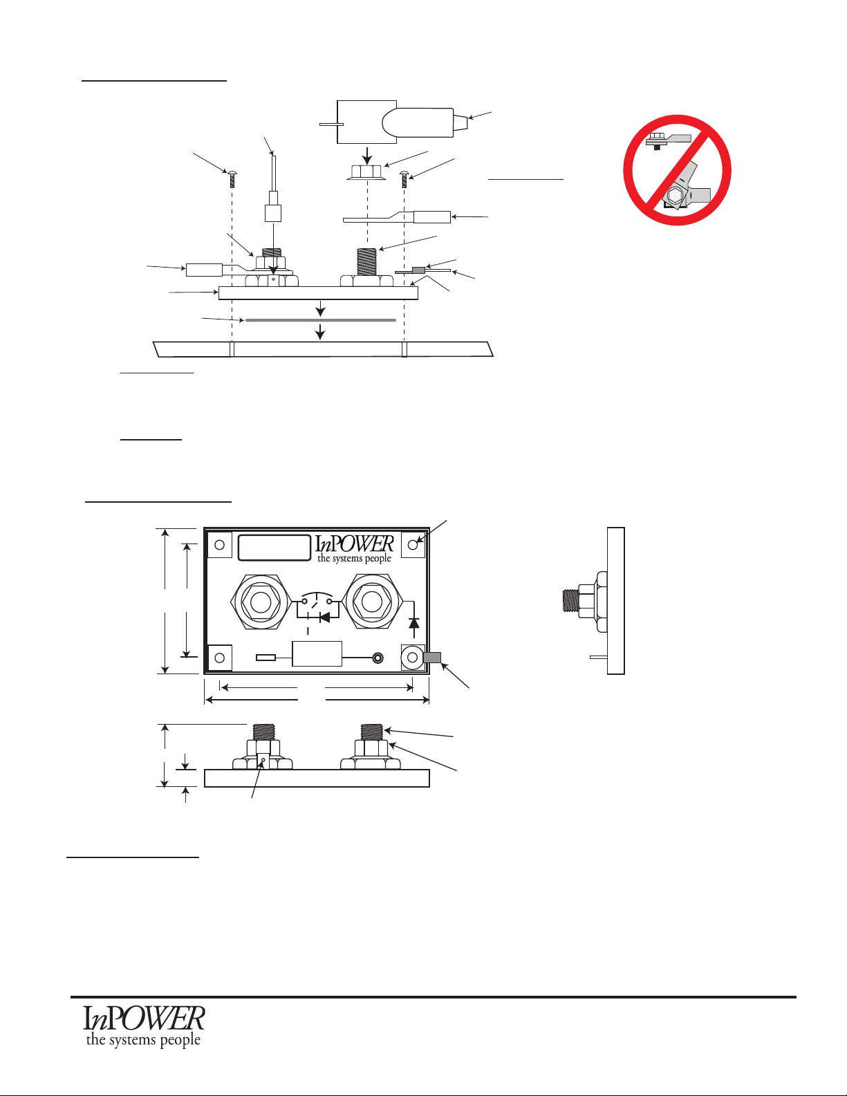
Installation Diagram
Mechanical Diagram
+BAT
Solid State Contactor
LVD20-200
Lot #
Ground
Status LED
Controller
Control Input
Electronic Switch
LOAD
+BAT
2.85 2.10
3.60
4.35
1.10
0.30
Terminal lug to
ensure a good
ground.
0.187
Stainless steel locking nut
(furnished with product)
3/8 - 16 stainless steel
threaded stud
All dimensions in inches. Not to scale.
Control Input Terminal
3/8 - 16 stainless steel threaded stud
Cable & Lug
Nut
Optional Terminal boot
Mounting screws (4 Required,
8-32) - Not provided
To 12 Volt Loads
Ground wire & lug terminal
To a good quality ground
Ground pad (4 places)
Thermal transfer pad
IMPORTANT!
Torque mounting screws
to 5 Inch Pounds
IMPORTANT!
Torque cable lug nuts to:
Minimum: 10 Foot pounds
Maximum: 15 Foot pounds
Control wire
and 1/4inch
female Faston
terminal
LVD20 Disconnect
To 12 volt battery
(+) and fuse
METAL MOUNTING SURFACE
NOTE - If the mounting screws cannot
provide a good quality ground you must
install a ground lug terminal and ground wire.
IMPORTANT!
The mounting surface provides a means to remove heat that is generated by the LVD.
If this surface is a poor conductor of heat the LVD will have alower currrent rating than
if the surface is a good conductor of heat with a sufficientlylarge area.
LVD20 to be mounted in a dry area, free of water or chemical spray.
NOTE - DO NOT DRILL OUT MOUNTING
HOLES TO ACCOMMODATE LARGER
MOUNTING SCREWS.
WARNING:
1. Do Not Stack terminals on the BAT, LOAD, or GND Pads (the nuts may loosen).
2. Make certain that torque specs are adhered to and that all nuts will not back off or loosen (locking nuts)
Do Not Stack Lugs!
If more power terminations are needed, use a
Power Junction Post or Termination Block
Testing Procedure
Make the following resistance measuremens with a digital multimeter with all wires removed from the LVD.
1. Measure the resistance between the two power terminals (+BAT & LOAD). The resistance should be 200
KOhms.
2. Measure the resistance from the Control Input terminal to one of the ground pads. The resistance should be 120
KOhms.
3. Measure the resistance of each power terminal to a ground pad with the + probe on the power terminal.
4. The resistance should be 120 KOhms.
This manual suits for next models
2


