insys icom i-modul User manual
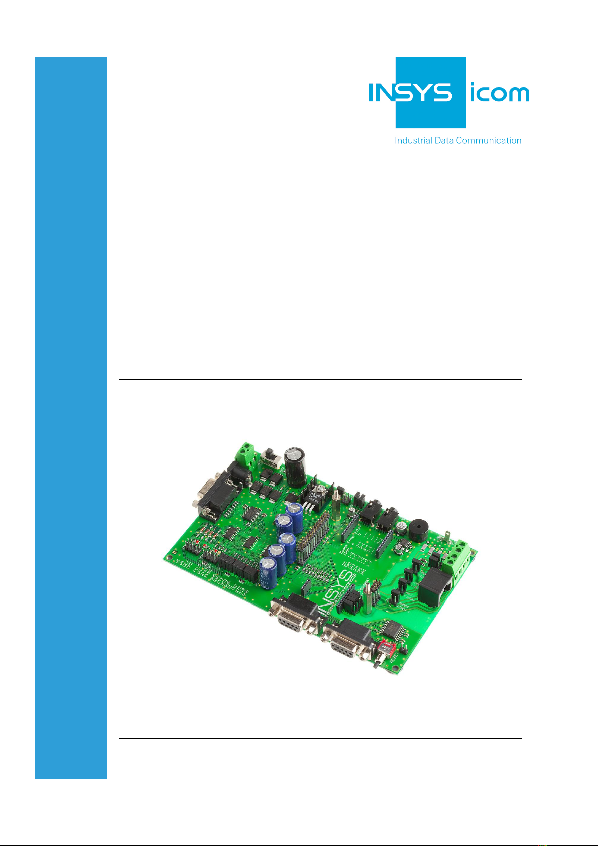
Evaluation Board
i-modul and Socket
Manual


Copyright © March 14 INSYS MICROELECTRONICS GmbH
Any duplication of this manual is prohibited. All rights on this documentation and
the devices are with INSYS MICROELECTRONICS GmbH Regensburg.
Trademarks
The use of a trademark not shown below is not an indication that it is freely availa-
ble for use.
MNP is a registered trademark of Microcom Inc.
IBM PC, AT, XT are registered trademarks of International Business Machine Cor-
poration.
INSYS®, e-Mobility LSG® and e-Mobility PLC® are registered trademarks of INSYS
MICROELECTRONICS GmbH.
Windows™ is a registered trademark of Microsoft Corporation.
Linux is a registered trademark of Linus Torvalds.
Publisher:
INSYS MICROELECTRONICS GmbH
Hermann-Köhl-Str. 22
D-93049 Regensburg, Germany
Phone: +49 941 58692 0
Fax: +49 941 58692 45
Internet: http://www.insys-icom.com
Date: Mar-14
Item: 31-22-09.001
Version: 1.0
Language: EN

Content
4Mar-14
1Overview ............................................................................................... 5
2Technical Specification .......................................................................... 6
2.1 Connectors.......................................................................................................... 6
2.2 Multi-pin connectors ........................................................................................... 6
2.3 Jumpers.............................................................................................................. 7
3Initial operation ...................................................................................... 8
3.1 Configuration of i-modules .................................................................................. 9
3.2 Configuration of Socket mode........................................................................... 10
3.3 Step-by-step inital operation instructions........................................................... 10
4Evaluation Board and module plug ports .............................................. 11
5Circuit diagram .................................................................................... 14

1Overview
The Evaluation board is intended to be used for customer specific implementations
and tests for the following INSYS i-modul and INSYS socket products:
Modem
ISDN
GSM
EDGE
HSPA
Ethernet
GPRS
WLAN
Bluetooth
Special Features:
Socket and i-modul support
D-SUB listen ports for RxD and TxD
Phone jack for speaker
Phone jack for microphone
Terminal and coaxial power supply
Support for 3.3 and 5V modules, adjustable by jumper

Technical Specification
Fehler! Kein Text mit angegebener
Formatvorlage im Dokument.
2Technical Specification
Dimensions:
160mm x 100mm
Power supply:
9 VAC - 12 VAC
10 VDC - 15 VDC
Current drain:
max. 1.5A (Peak at GSM)
max. 0.3A (ISDN, Modem, Ethernet, WLAN)
2.1 Connectors
CON401
Screwing terminal for power supply
CON11
Coax jack for power supply
CON16
SUB D jack for RS232 connection
CON301
RJ45 jack for Modem/ISDN/Ethernet- connection
CON303/CON304
Screwing terminal for phone connection
CON2
SUB D jack for RS232 listen port RxD
CON3
SUB D jack for RS232 listen port TxD
CON13
3,5mm jack for speaker
CON12
3,5mm jack for microphone
2.2 Multi-pin connectors
CON18
Multi-pin connector for field strength, OH, status, sync
JP100
Multi-pin connector for RS232 signals
CON110
Multi-pin connector for RESET
J401
Multi-pin connector GND and VCC connection
CON17
Multi-pin connector UE/UA/UE2/UA2

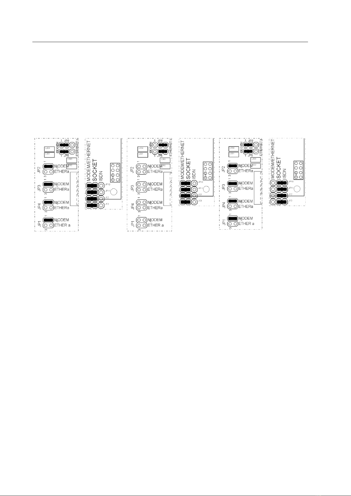
2.3 Jumpers
JP1
Setting for i-modul (Pin assignment)
JP2
Setting for i-modul (Pin assignment)
JP3
Setting for i-modul (Pin assignment)
JP4
Setting for i-modul (Pin assignment)
JP5
Setting for i-modul (Pin assignment)
JP6
Setting for i-modul (Pin assignment)
JP7
Microphone supply
JP100
Jumpers for serial interface
JP8
Jumper for on-board speaker
JP9
Switching between 3,3V (open) und 5V (bridged)
JP10
Setting for Socket
JP11
Setting for Socket
JP12
Setting for Socket
JP13
Setting for Socket

Initial operation
Fehler! Kein Text mit angegebener
Formatvorlage im Dokument.
3Initial operation
In principle there is a difference in configuration of i-modules and socket modules.
Depending on the plugged-on module the correct jumper settings must be checked
before switching on the evaluation board.
Warning!
With voltage not adjusted properly the is danger of
overheating of components..
Hot surfaces!
Take care jumper JP9 is configured properly.
In case components become hot, cut electrical
supply and have components cool down
Danger of severe injury and of damage of components

3.1 Configuration of i-modules
Use jumpers J1-J6 and JP9 (bridged = 5V) if you want to configure an i-modul Mo-
dem/ISDN or an i-modul Ethernet/WLAN bridge.
The jumper settings for i-modul Modem correspond to the jumper settings for i-
modul ISDN.
Configuration
Modem/ISDN
Configuration
Ethernet a/WLAN bridge a
Configuration
Ethernet b/WLAN bridge b
Note
When using an i-modul GSM, GPRS, WLAN serial and Blue-
tooth the jumpers JP1 –JP6 as well as the connectors CON301
and CON303/304 are without function.
Initial operation
Fehler! Kein Text mit angegebener
Formatvorlage im Dokument.
3.2 Configuration of Socket mode
In order to configure the evaluation board for socket modules (Modem/Ethernet,
ISDN) the jumpers JP9 –JP13 have to be used. JP9 should be open with 3,3V-
modules.
The jumper settings for Modem correspond to the Ethernet settings.
Configuration Modem
Configuration Ethernet
Configuration ISDN
3.3 Step-by-step inital operation instructions
Please follow these steps when plugging on a new i-modul or socket module:
1. Plug on the module carefully.
2. Configure the modul type with jumpers JP1 –JP6 and JP9 (i-modul and socket)
respectively JP10 –JP13 (socket only).
3. Connect the serial interface CON16 by a standard serial cable with your
computer.
4. Connect the power supply either by connector CON401 or by jack CON11. The
polarity is irrelevant.
5. Start your terminal program on your computer (e.g. Hyperterminal or TeraTerm).
6. Switch on power supply (LED “PWR” is lit).
7. Type AT<RETURN> in the terminal program of your computer.
8. The module answers by sending OK back to the terminal program. When using
a module without the autobauding feature you have to check the baud rate of
your terminal program before the communication can be established
successfully. If there is no answer from the module even after checking the
communication settings you have to immediately switch off the power supply
and check if the i-modul or socket module is plugged on correctly and if all
jumpers are set as described in this manual.
4Evaluation Board and module plug ports
Port
for i-modules
144/336/56k
GSM
GPRS
Bluetooth
Ethernet
WLAN

Evaluation Board and module plug ports
Fehler! Kein Text mit angegebener
Formatvorlage im Dokument.
Port
for i-modul
ISDN HIT
ISDN HIX
Note
The bolt has to be removed before
plugging on the module.
Port
for socket mod-
ules

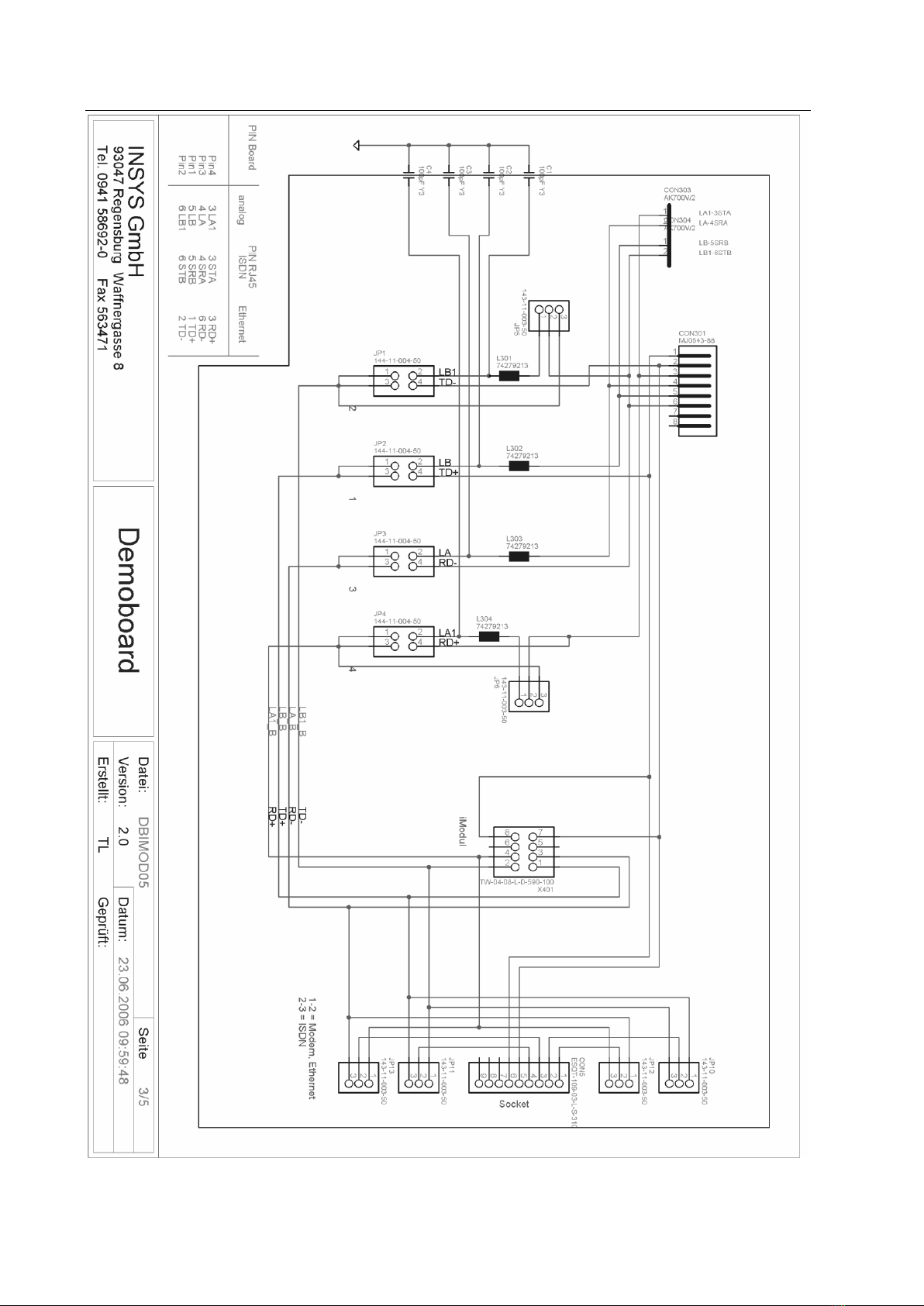
Circuit diagram
Fehler! Kein Text mit angegebener
Formatvorlage im Dokument.
5Circuit diagram

Circuit diagram
Fehler! Kein Text mit angegebener
Formatvorlage im Dokument.


Table of contents


