INTEGRATED PAVING CONCEPTS Rapid Finisher 2 User manual

Updated: Nov 2012
Rapid Finisher 2
Operations Manual

2
Contents
1. Introduction
2. Safety
3. Parts List
4. Specifications & Dimensions
5. Storage Case
6. Preparing for Work
7. Operating Procedure
8. Cleanup
9. Parts List
10. Service

3
The Rapid Finisher 2 is designed for the application of asphalt coatings. This electrically powered
brush will enable the applicator to apply coatings to large projects quickly and efficiently reducing
both time and labor costs.
This fast and easy machine works in a similar manner to a floor polisher, with a multi-brush
Cartridge that effortlessly works the coatings into the asphalt surface at variable speeds up to
70 rpm. Each brush Cartridge has a usable life of 5,000 ft² (500 m²) or more, and the brushes
are easily replaceable.
Introduction
4
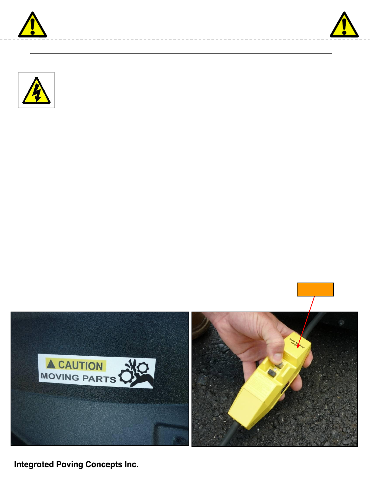
Safety
Danger Electric Shock!
∆Never operate machine without the Ground Fault Interrupt (GFI) in line.
Failure to do so could result in death from electric shock
∆Never immerse electrical components in water. Follow the cleaning
instructions in this manual carefully
∆Regularly check to ensure that no electrical wires are worn and exposed.
Replace or repair before use
∆Always unplug the machine when making any repairs or when accessing the
electrical components
Danger! Moving Parts –the Brush Cartridge turns with enough force to cause serious injury.
∆Always unplug the machine before changing the Brush Cartridge
∆Keep fingers, feet and loose clothing away from the brushes when in operation
∆Always keep a firm grip on the handle when operating or it could swing out of your hands and cause
injury or damage
∆Never mechanically hold the throttle open. The throttle is designed to shut off the moment the
operator lets go. If the throttle remains open the machine could cause serious injury and property
damage
Caution Hot! –the motor can become quite hot, even exceeding the temperature of boiling water!
Safety Wear –To avoid injury, always wear safety glasses, ear protection, long pants and steel toed boots
and gloves when operating this equipment.
Ensure that everyone who operates this machine has read and understood this manual.
GFI

5
A
B
CD
E
F
G
H
A. Main Body and Motor Assembly with 2 replaceable liners
B. Lower Handle
C. Upper HandleAssembly
D. Brush Cartridge Assembly with brushes
E. Spare Brush Cartridge
F. Spare Brushes (6 pieces)
G. Brush mounting hardware
H. Lower Case Assembly with 2 replaceable liners
Parts List

6
Specifications and Dimensions
Rapid Finisher 2 Specifications
Machine Weight
(Not including Case) lbs
(kg)
Source Electrical
Power 110 or 220 VAC
Electric Gear Motor
¼ HP (186
Watts)
Gear Ratio 40:1
Motor Voltage Up to 110 VDC
Electric Current 2.5 Amps Max.
at 110 VAC
Brush Cartridge
Speed 0 –76 RPM
Handle at 25°
from Horizontal
Handle at 50°
from
Horizontal
32.5”
0.83 m
62”
1.57 m
Locking Handle is adjustable in height from
25°to 50°from horizontal in 5°increments
Generator: Use Honda
inverter type generators only
for the best performance. 3000
watts is recommended to run
the Rapid Finisher 2
7
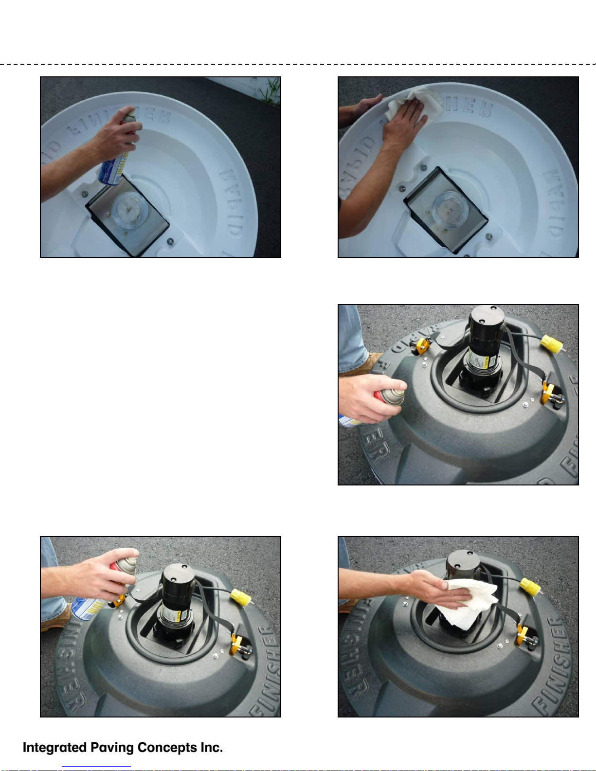
Preparing for Work
Preventing Coating Buildup
Using a bond breaker on the lower and upper surfaces of
the main body can extend the life of your machine, as
coating buildup on the motor will prevent proper cooling
Use WD40 or cooking oil spray to lightly coat the upper
and lower surfaces. WARNING: don’t use a heavy coat
or allow drips because your coating job may be
compromised if the bond breaker is allowed to mix with
the coatings. Use a cloth to wipe up all excess oil.
Make sure that the motor has a bond breaker applied.

8
Preparing for Work –Cont’d
First, make sure the “legs” on the Cartridge
Lock are aligned with the three protrusions on
the Aluminum Clutch
Attaching and Locking the Brush Cartridge
Place the Brush Cartridge onto the Aluminum
Clutch
Rotate the Cartridge clockwise with a sharp
motion to seat the Cartridge onto the Clutch Rotate the Cartridge Lock counterclockwise to
lock the Cartridge onto the Clutch.
IMPORTANT: to prevent damage to the
Cartridge, always make sure the Cartridge Lock
is properly positioned
9
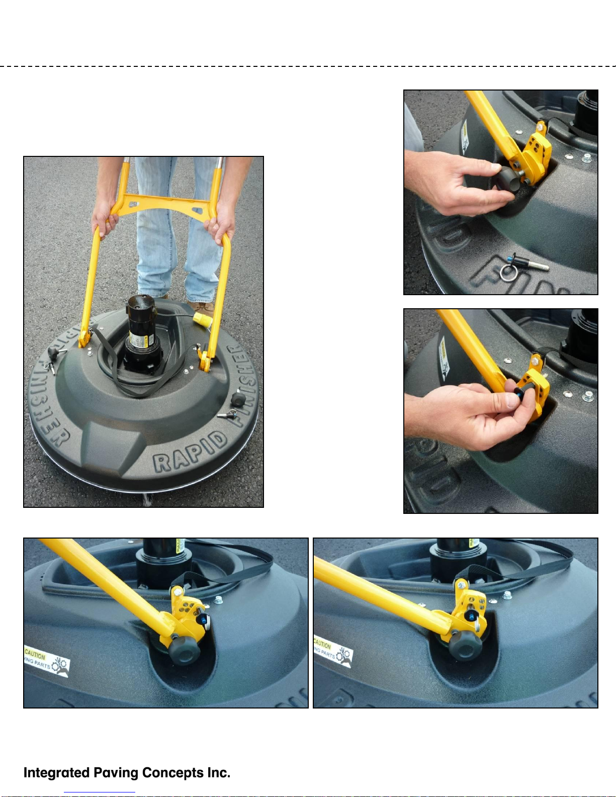
Preparing for Work –Cont’d
Secure and tighten
the handle with the
Lobed Hand Wheel
fasteners…
use the Ball Lock Pins
to select the desired
handle height
By using both the upper and lower holes for the Ball Lock Pins the handle angle can be adjusted in 5°
increments
Attach Lower Handle
Remove the Lobed Hand Wheel
fasteners and Ball Lock Pins and place
the lower handle in position

10
Operating Procedure
Throttle Control
Make sure you are holding both handles securely
before pushing the throttle button.
To adjust the rotation speed of the brushes
simply adjust the dial on the control box.
11
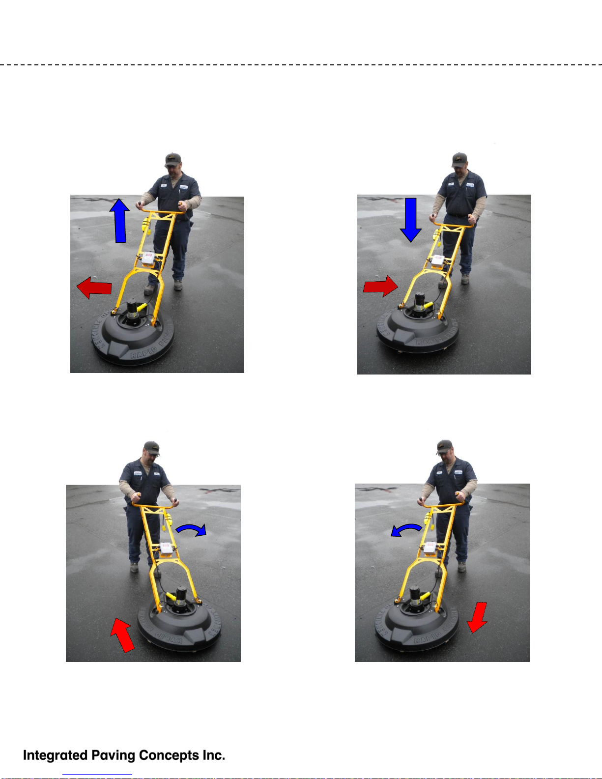
Operating Procedure –Cont’d
Directional Control
Let the machine do the work for you. Depending on how you manipulate the handle, the machine will
move in different directions
LIFT the handle and the machine will move to
the RIGHT. NOTE: use moderate movements. LOWER the handle and the machine will move
to the LEFT.
TWIST THE HANDLE TO THE LEFT and the
machine will move BACKWARDS. TWIST THE HANDLE TO THE RIGHT and the
machine will move FORWARDS.
12
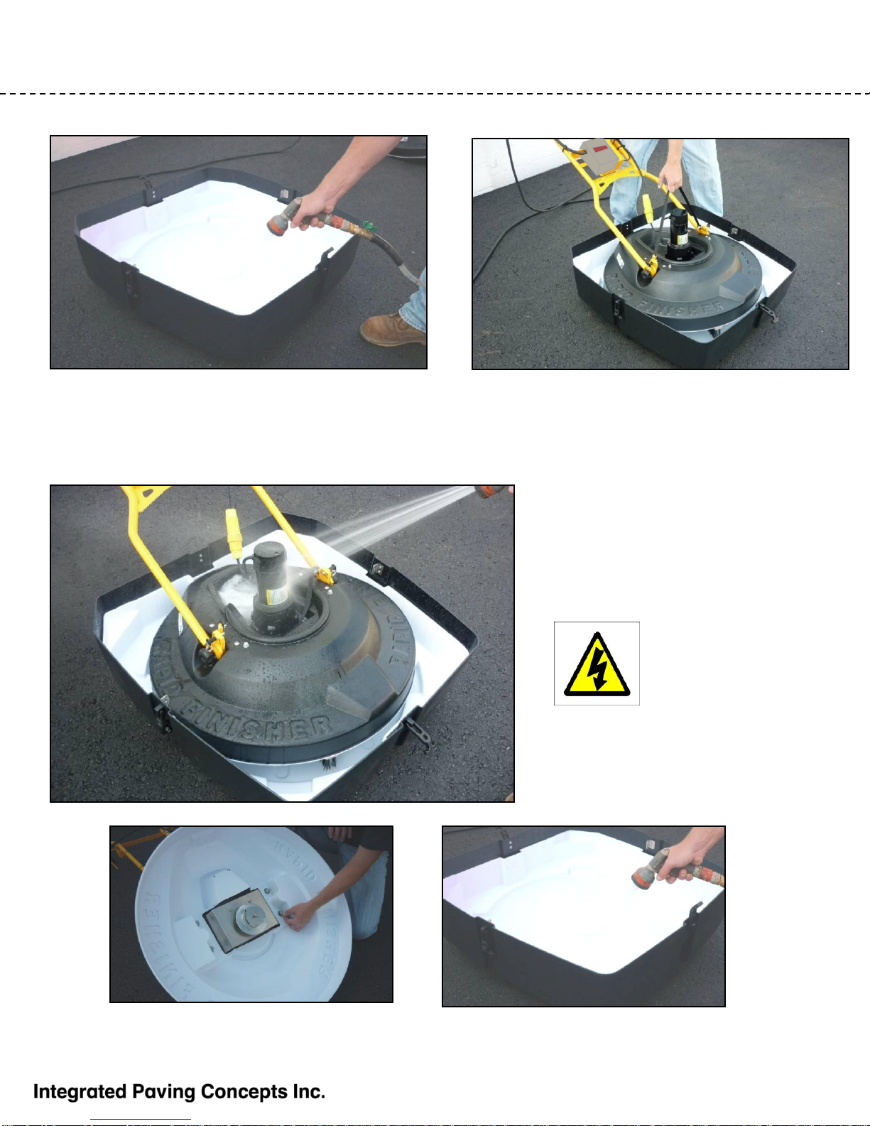
Cleanup
Cleaning the Rapid Finisher 2
Put about 1 –2 inches (25 –50 mm) of water
into the Lower Case that has the Liner/s Lower the machine into the water and run the
brushes at a slow speed until the brushes are
clean
The motor can be washed with
standard hose pressure. CAUTION:
ALWAYS UNPLUG THE MACHINE
FROM THE GENERATOR FIRST.
Never use a pressure washer
CAUTION: NEVER SPRAY OR
IMMERSE THE ELECTRICAL BOX
ON THE HANDLE . USE A DAMP
CLOTH TO WIPE IT DOWN INSTEAD
If the Liners need to be replaced a liner kit (part number 80-0-403A), that contains 2 Base Liners
and 2 Case Liners, is available from Integrated Paving Concepts. The Base Liner is secured by 4
wing nuts and large washers on the underside.
To extend the life of the brushes place the Rapid Finisher 2 in water when it is not being used.

13
REF DESCRIPTION QTY PART NUMBER
1 RF2 Main Body Asbly 1 80-0-400E1
1.1 RF2 Main Body ABS 1 80-0-40002
1.2 DC Gear Motor 1 EC-0-0-034
1.3 RF2 Handle Receiver 2 n/a
1.4 RF2 Bridge Bracket 1 n/a
1.5 RF2 Handle Backing Bracket 2 n/a
1.6 RF2 Aluminum Clutch 1 80-0-40094
1.7 RF2 Brush Cartridge Lock Bracket 1 n/a
1.8 RF2 Brush Cartridge Lock Spring 1 MC-0-0-109
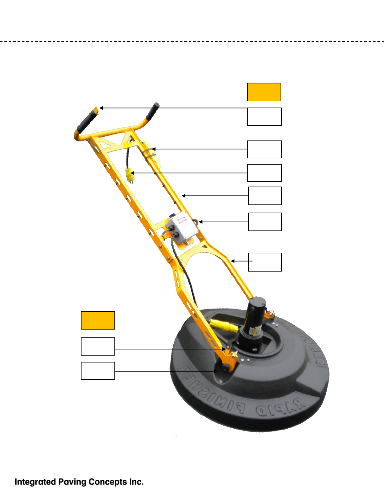
2 RF2 Handle Asbly 1 80-0-400E2
2.1 RF2 Lower Handle 1 n/a
2.1.1 3/8” Lobe Hand Wheel Fastener 2 MC-0-0-280
2.1.2 5/16” Ball Lock Pin 2 MC-0-0-271
2.2 RF2 Upper HandleAsbly 1 n/a
2.2.1 Red Start/Stop Button 1 n/a
2.2.2 RF2 Ground Fault Interrupt ( GFI) 1 80-0-40011
2.2.3 Male power connection 1 n/a
2.2.4 Brush rotation control box n/a
3 RF/RF2 Brush Cartridge Asbly 2 80-0-401
3.1 RF/RF2 Brush Cartridge with Clutch 2 80-0-40061
3.2 RF/RF2 Brushes (come in pack of 24) 12 80-0-410
Parts List
(See the Following Page for Illustrations)
14
Parts List - Illustrations
5
5.3
2.1
2.2.1
2.2
2.2.2
2.1.1
2.1.2
2.2.4
2.2.3
2
2

15
1.2
1.1
1.3
1.4
1.6 1.5
1.7
3.1
3.2
Parts List –Illustrations (cont’d)
3
1

16
Service
Integrated Paving Concepts Inc. is committed to providing the best possible
after-market service. If you require parts, warranty information or service please
visit our website at:
www.streetprint.com
Or call our TechnicalAssistance line:
1-800-688-5652
.
Table of contents


