Interfire TUNN T-1000M User manual

MONO CHANNEL / 2 CHANNEL / 4 CHANNEL
AUTOMOTIVE AMPLIFIER
INSTRUCTION MANUAL
T-1000M
T-270 / T-2100 / T-2130
T-460 / T-480
By


1
free installation.
Congratulations on your Purchase
• Four Class''AB'' High-Current DualDiscrete Drive Stages.
• Class ''AB''Technology MOSFET PWM Power Supply.
• Bridgeable &TRI-Mode Operation.
• Continuously Variable 12dB/Octave HighPass & 12dB
/Octave Low PassCrossover.
• Subwoofer Variable Crossover forDeep Bass Control.
• Enhanced BassBoost +12dB @45Hz.
• Silver PlatedRCA, Power & Speaker Terminal.
• Soft Start& Muting.
• Overload, Thermal and ShortCircuit Protection.
• Power &Protection indicator.
• Bass LevelRemote Control(16.4Fit) -T-1000M / T-2130
Features
Your new high fidelity bridgeable/stereo amplifier is designed to deliver maximum enjoy
ment and oneyear of troublefree service. Pleasetake a fewmoments to readthis manual
thoroughly. It will explain the features and operation of your unit and help insure trouble
Precautions: Read First!
authorized installer. It's your car!
• If afterreading the directionsyou feel uncomfortableabout installing theamplifier in your
car, or not equipped or competent to do so, you should have the amplifier installed by an
• Negative battery terminal must be disconnected before any electrical connections are made.
• Be surechoose a locationthat provides substantialventilation for theamplifier. The most
preferred locations would be in your car's trunk, under the front seats or on the back wall
of a truck.
• The location chosen should provide at least 2" of clearance above the amplifier for adequate
ventilation.
• If the amplifier is to be mounted vertically be sure that it is in a place where adequate air
will flow alongthe length ofits heatsink finsfor cooling.
• NEVERmount the amplifier upside down,this willcause theheat to rise backinto the
amplifier causing thermalshutdown or possiblepermanent damage.
• NEVER mount the amplifier in a location that is subject to direct sunlight or exposed to
moisture.
• Be sureto mount the amplifier to astrong, solid surface which will notgive way underthe
stress of asudden stop oraccident.
• Make sure that the mounting screws will not penetrate the gas tank, brake and fuel lines,
wiring or othercritical parts ofyour car wheninstalled.

• NEVER operate the amplifier without the proper power and ground wire, 10 gauge minimum.
• NEVER operate the amplifier without proper fusing. Fuse holder must be located with in
0.5 meters from the battery. This fuse is to protect the car not the electronics. In case of a
short, the fuse will blow instead of the wire burning up. Using other than the recommended
fuse ratings at the battery and at the amplifier may cause damage to the amplifier and will
• Do not run wiring underneath or outside the car since exposure to the elements may cause
the insulation to deteriorate rapidly, resulting in short-circuits and/or intermittent operation.
• To help minimize interference, it is best to run the power cables along the opposite side
.
• Whenever wires pass through metal, rubber or plastic grommets must be used to prevent
• Whenever possible, use cable ties, mounting clamps and similar wiring aids. (available
from an electrical supply or auto parts store) Adding stress relief loops to wiring is also
• It is best to test the system before the amplifier is mounted and interior of car is reassembled.
• If the temperature inside your car reaches extreme levels(such as sitting locked up for
several hours in the hot sun or exposed to a very cold winter's day)the amplifier may go
into protection mode and shut off. Leave the unit off until the ambient temperature returns
• The amplifier operates with any vehicle using a 12 volt negative ground system. If you are
not sure of the type of electrical system in your vehicle, consult your authorized dealer or
• NEVER ground the speaker leads and NEVER allow the speaker leads to come in contact
• Remote turn on wire must be switched by the radio does not have a remote turn on or
antenna output, connect to wire that has a positive 12 volts when the key is turned to the
• Do not listen to high volumes for extended periods of time or hearing damage may occur.
2
CONTINOUS EXPOSURETO SOUNDPRESSURE LEVELSOVER 100dBMAY
CAUSE PERMANENT HEARINGLOSS. HIGH POWERED AUTOSOUND SYSTEM
SENSE ANDPRACTICE SAFE SOUND.
MAY PRODUCESOUND PRESSURE LEVELS WELL OVER 130dB. USE COMMON
void your warranty.
all cables should be run beneath carpets and inside trim pieces.
from the audio cables
the metal from wearing through the installation and causing a short.
advisable to prevent straining or breakage.
to normal.
qualified mechanic.
with each other. Speaker wire should be 18 gauge or larger.
accessory. If the amplifier does not turn off the battery will die.
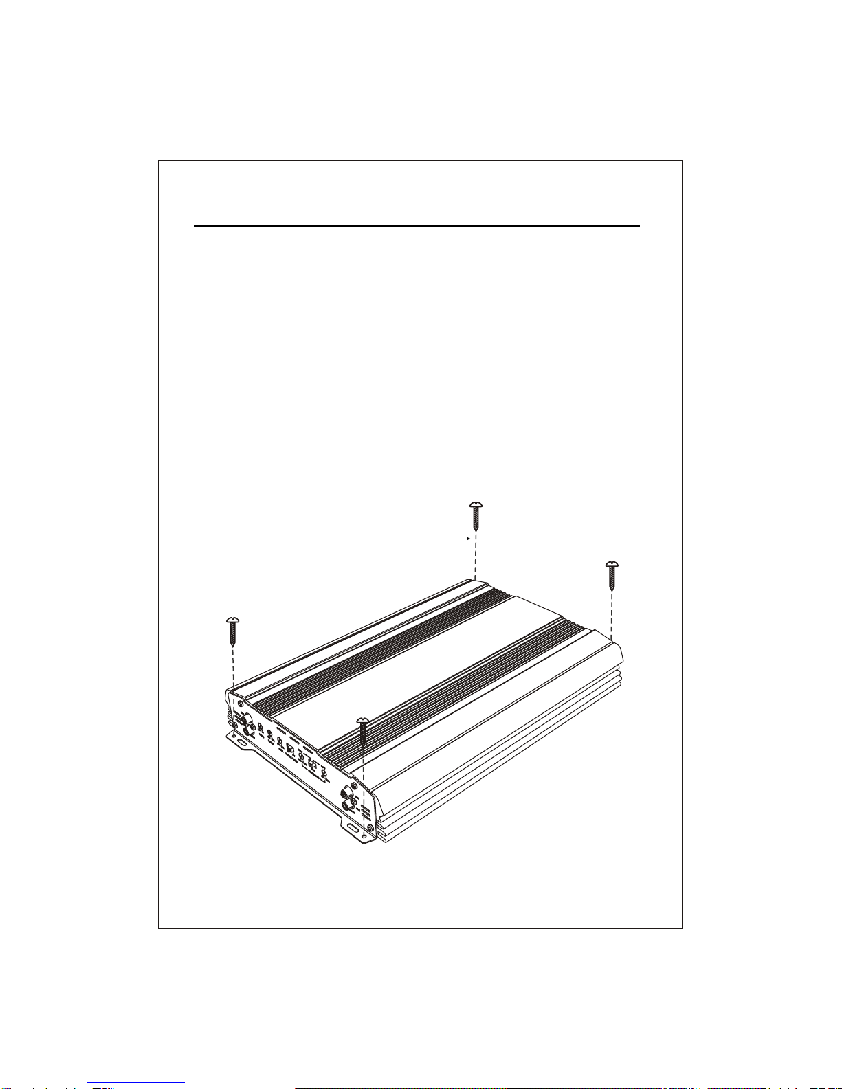
INSTALLATION
1. After reading precaution, decide where you are going to install the unit. Also, see Fig.1.
2. Once thelocation has beendetermined, place theamplifier into position.Using a felttip
pen or pencil mark the four holes to be drilled for mounting. NEVER use the amplifier as
a template for drilling. It is very easy to damage the amplifier surface in this manner.
3. Remove amplifier. Drill four 3.5 m/m holes into mounting surface. If you want to mount
4. If possible, test the system to ensure it is operating correctly before final mounting of
5.
INSTALLATION DIAGRAM
FIG.1
3
Self Tapping Screws
MOUNTING:
Mount the amplifierusing the supplied4 self tappingscrews.
the amplifier to MDF or wood panel, drill four 3.0m/m diameter holes into mounting surface.
the amplifier.

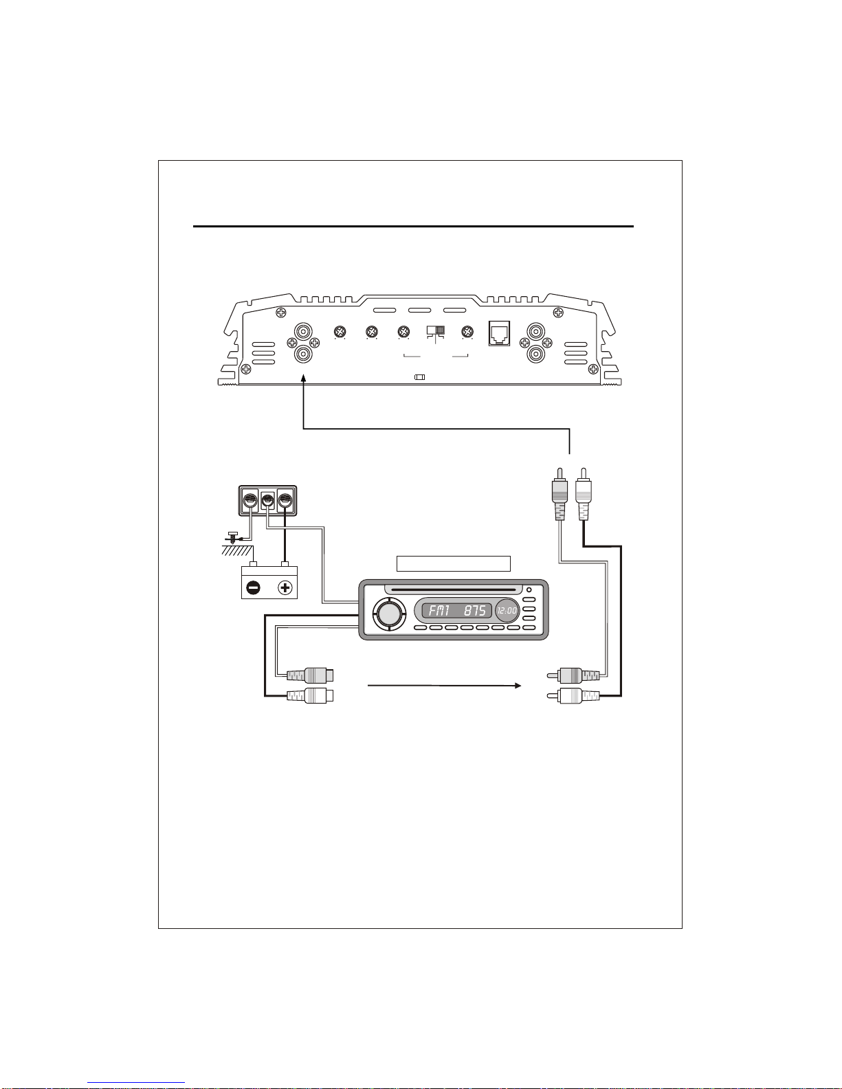
POWER CONNECTIONS
CONNECTIONS
INPUT CONNECTIONS
It is important to have good quality power and ground connections. Remember, to complete
an electrical circuit, the ground connection is just as important as the positive power
connection. Before any power connections are made, disconnect the ground cable at the
When the power supply lead, memory backup lead or ground lead are extended use a 5mm²
(AWG5) or larger automotive grade cable which will withstand friction and heat to safe
GND = Connect the proper gauge ground wire to the amplifier "GND" terminal. Locate the
position on the chassis of the car to which the amplifier is to be grounded. The surface must
be free from any paint or dirt. This can be accomplished with a small grinding bit, sand
paper or wire wheel. NOTE: Do not ground the amplifier to the "frame of the car. The frame
on most cars and trucks is not grounded to the chassis(body). Use Solder or a clamp ring to
connect the ground wire. Pre-drill the prepped chassis to bolt the ground ring terminal with
nut, bolt and lock washers. Insulate metal and connector with paint or silicon to prevent
rust and oxidation. Silicon also works great to prevent nuts and bolts from working loose in
a harsh environment of an automobile. Upon completion of the ground connection, grab
wire or connector and confirm that it is a solid connection. To prevent engine noise, it is
REM = Connect the remote wire (power antenna output) from the head unit to the remote
turn-on wire of the amplifier. If the head unit is not equipped with a remote/antenna output,
locate a wire that is controlled by the accessory position of the key. It is important to have
the amplifier turn off with the radio or key. If the amplifier remains on, the result will most
12V = Connect the proper gauge power wire to the amplifier "B+" terminal. Run wire to
wards the fuse holder that is no greater then 0.5 meters from the battery. Remember, the
fuse is to protect the safety of the car in the case of a short. Connect fuse holder to battery,
4
This amplifier will accept low level inputs only. Low level is the same as line level. The low
level signal is carried through RCA cables. It is preferred to use low level inputs to the amplifier
if the head unit is equipped with the low level outputs. If not, you can use a "high to low
Connect the low level/line level RCA cables from the head unit, or signal processor, to the
converter" available throughyour local caraudio shop.
line level inputon the amplifier. See Fig.2 system wiring diagrams.
battery.
grade against fires occurring as a result of short-circuiting.
recommended to ground the head unit and other audio electronics in the same location.
likely be a dead battery.
but do not install fuse at this time.

5
FIG.2
MONO CHANNELSYSTEM WIRINGDIAGRAM
AUTO - ANTENNA LEAD
CH1 CH2
CAR STEREO HEAD UNIT
B+
GND REM
LINE IN LINE OUTREMOCON
GAIN BASS L.P.FPHASE
6V 0.2V 0dB 12dB 50Hz 250Hz
CH1
CH2
CH1
CH2
0180
O O
6
2 CHANNELSYSTEM WIRINGDIAGRAM
FIG.2
B+
GND REM
AUTO - ANTENNA LEAD
CH1 CH2
CAR STEREO HEAD UNIT
LINE IN LINE OUT
REMOCON
L.P.F
L.P.F
H.P.F
H.P.F
6V 0.2V 0dB 12dB 50Hz 250Hz
FLAT
80Hz 1.2KHz
CROSSOVER
CH1
CH2
CH1
CH2
BASSGAIN

7
FIG.2
B+
GND REM
4 CHANNELSYSTEM WIRINGDIAGRAM
CH3 CH4CH2CH1
AUTO - ANTENNA LEAD
CAR STEREO HEAD UNIT
LINE IN LINE IN
GAIN GAINBASS BASS
CROSSOVER CROSSOVER
6V 0.2V 0dB 12dB 50Hz 500Hz
CH1
CH2
CH3
CH4
50Hz 500Hz 0dB 12dB 6V 0.2V
CH 1/2 CH 3/4
FLAT
L.P.F H.P.F
FLAT
L.P.FH.P.F

ON
PROTECT
POWER B+GND REM FUSE
SPEAKER
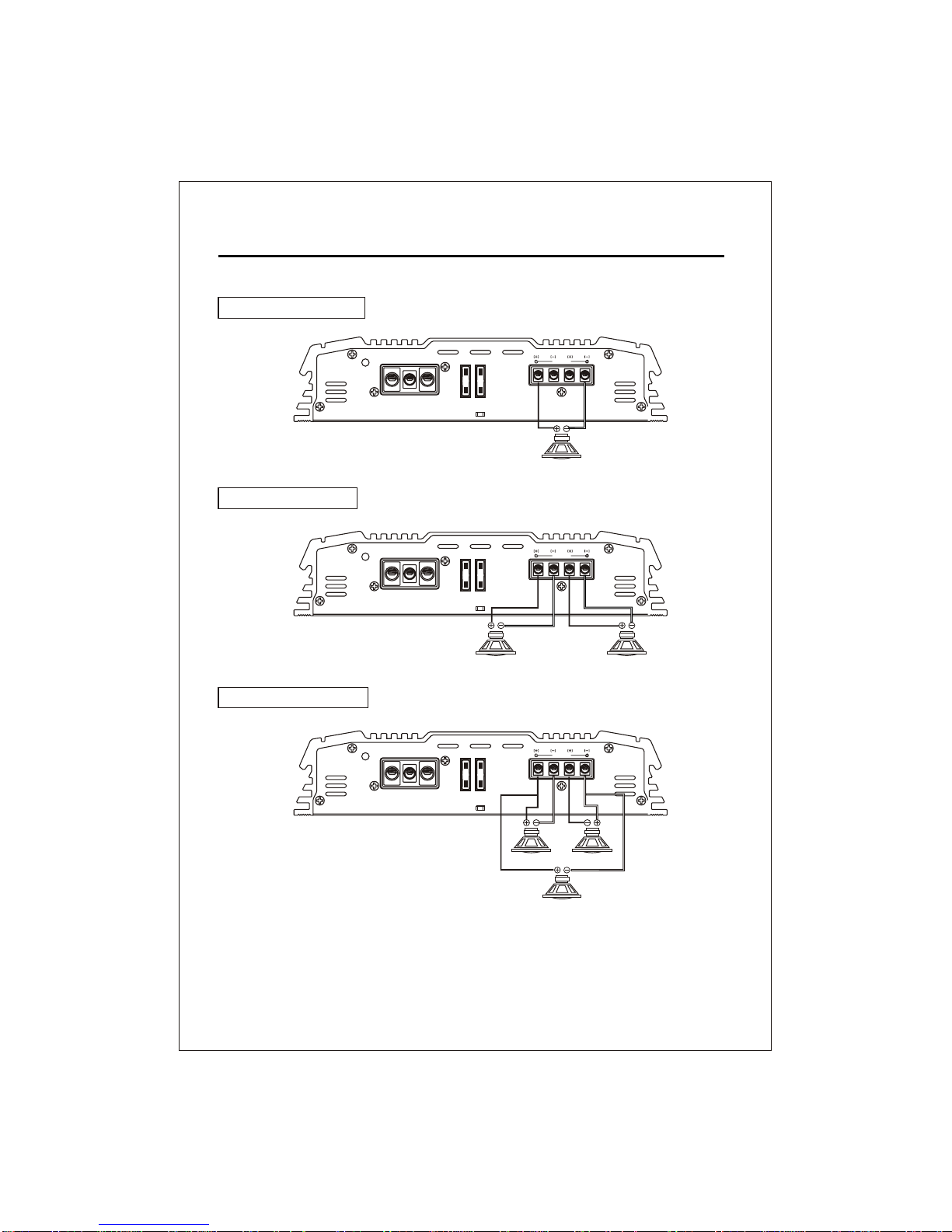
This amplifier can operate in one, two or three channel mode. The minimum impedance for
single channel (bridged/mono) operation is 4 or 8 ohms. Tri channel power is referred to
stereo and mono at the same time. Minimum impedance remains the same for three channel
(front /subwoofer) systems as long as proper passive crossovers are used. Connect right
and left speaker wire to corresponding speaker output terminals of the amplifier. Be sure to
have the positive wire from the speaker connected to the positive speaker terminal of the
amplifier and the negative wire from the speaker must connect with the negative speaker
terminal of the amplifier. Reversing any of these connections will result in the speaker cones
moving out of phase which causes bass cancellation. See Fig.3 Speaker Output Connections.
SPEAKER CONNECTIONS
MONO CHANNEL SPEAKER WIRING DIAGRAM
1 SPEAKER BRIDGED
2 SPEAKER STEREO
8
4 - 8 Ohm
1CH
FIG.3
ON
PROTECT
POWER B+GND REM FUSE
SPEAKER
1CH
2 CH
2 - 4 Ohm
ON
PROTECT
POWER B+GND REM FUSE CH1 CH2
BRIDGED
SPEAKER
ON
PROTECT
POWER B+GND REM FUSE CH1 CH2
BRIDGED
SPEAKER
2 CH SPEAKER WIRING DIAGRAM
2 - 4 Ohm
1 CH 2 CH
1 SPEAKER BRIDGED
2 SPEAKER STEREO
3 SPEAKER TRI MODE
4 - 8 Ohm
1CH
ON
PROTECT
POWER B+GND REM FUSE CH1 CH2
BRIDGED
SPEAKER
FIG.3
SPEAKER CONNECTIONS
9
WOOFER 2CH+1CH
4 - 8 Ohm
2 CH
3 CH
1 CH
4 - 8 Ohm

4 CH SPEAKER WIRING DIAGRAM
2 SPEAKER BRIDGED
2 SPEAKER + 1 SUBWOOFER
4 SPEAKER STEREO
6 SPEAKER HEX MODE
10
SPEAKER CONNECTIONS
SPEAKER
BRIDGED
CH1
CH3 CH2
CH4
ON
PROTECT
POWER B+GND REM FUSE
SPEAKER
BRIDGED
CH1
CH3 CH2
CH4
ON
PROTECT
POWER B+GND REM FUSE
SPEAKER
BRIDGED
CH1
CH3 CH2
CH4
ON
PROTECT
POWER B+GND REM FUSE
4-8 Ohms
1 CH
2 CH
SUB WOOFER
3 CH
4-8 Ohms
2 CH1CH
2-4 Ohms 2-4 Ohms
5 CH
4-8 Ohms
6 CH
4-8 Ohms
4-8 Ohms 2 CH4 CH1 CH 3 CH
SPEAKER
BRIDGED
CH1
CH3 CH2
CH4
ON
PROTECT
POWER B+GND REM FUSE
2-4 Ohms 2 CH4 CH1 CH 3 CH

11
ADJUSTMENTS
1.Set to the "H.P.F" position when the amplifier is used to drive a tweeter/midrange system.
The frequencies below the crossover point will be attenuated at 12dB/octave. Permits
adjustment of the crossover frequency ,by rotating the knob to select any frequency
2.Set to the "L.P.F" position when the amplifier is used to drive a subwoofer. The frequencies
above the crossover point will be attenuated at 12dB /octave. Permits adjustment of the
crossover frequency, by rotating the knob to select any frequency between 50Hz to 250Hz
3.Set to the "OFF" position when the amplifier will be used for driving full-range speakers.
The full frequency band width (20Hz - 20kHz) will be output to the speakers without high
4.Level adjustment-The sensitivity adjustment is to allow the amplifier to work with many
different brands of head units. It allows input signal to vary between 350 millivolts to 5
volt from the head unit or other signal processor. Start by setting the sensitivity adjustment
to the "MIN" (3 volts).Using a cassette or compact disc that you are familiar with ,turn on
head unit to the 3/4 volume setting. Slowly turn up sensitivity adjustment towards the
"MAX" (200 millivolts) using a flat head screw driver. Stop turning on the onset of distortion
and turn back just a slight. The 3/4 volume setting is now the "maximum" volume for the
head unit. The goal is to keep the level control to the lowest setting yet still have enough
signal to drive the amplifier. This is done to prevent over driving the amplifier and to keep
system noise to a minimum. It is important not over drive speakers (at point of distortion)
this will cause permanent damage to the speakers. Also, if the amplifier itself is over driven,
5.The "BASS" function can be selected to increase low frequency response output, or
decrease frequency response output. The "BASS" function will be working at only "OFF"
between 80Hz to 1.2kHz & 50Hz to 500Hz as the crossover point.
& 50HZ to 500Hz as the crossover point.
or low frequency attenuation.
it could be damaged.
or "L.P.F" position.
• The BASS is adjustable from 0 ~ 12dB boost at 50Hz.
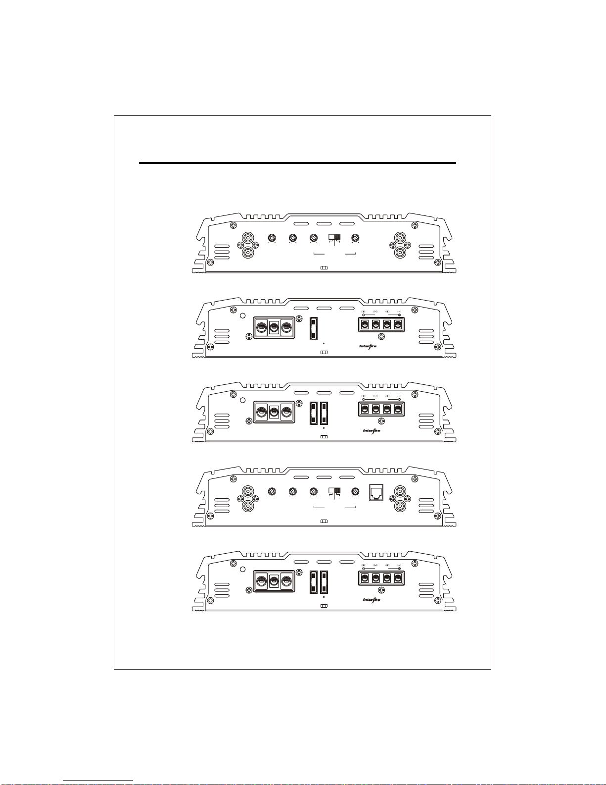
FRONT/REAR PANEL
12
2CHANNEL
ON
PROTECT
POWER B+GND REM FUSE CH1 CH2
BRIDGED
SPEAKER
30A
TUNN
T-270
By
LINE IN LINE OUT
L.P.F
L.P.F
H.P.F
H.P.F
6V 0.2V 0dB 12dB 50Hz 250Hz
FLAT
80Hz 1.2KHz
CROSSOVER
CH1
CH2
CH1
CH2
BASSGAIN
ON
PROTECT
POWER B+GND REM FUSE CH1 CH2
BRIDGED
SPEAKER
25A 25A
T-2100
By
TUNN
LINE IN LINE OUT
REMOCON
L.P.F
L.P.F
H.P.F
H.P.F
6V 0.2V 0dB 12dB 50Hz 250Hz
FLAT
80Hz 1.2KHz
CROSSOVER
CH1
CH2
CH1
CH2
BASSGAIN
ON
PROTECT
POWER B+GND REM FUSE CH1 CH2
BRIDGED
SPEAKER
30A 30A
T-2130
By
TUNN
T-270,T-2100
T-270
T-2100
T-2130
T-2130
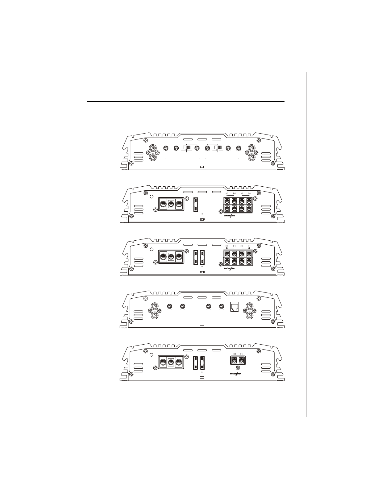
FRONT/REAR PANEL
13
4CHANNEL
MONO
CHANNEL
LINE IN LINE IN
GAIN GAINBASS BASS
CROSSOVER CROSSOVER
6V 0.2V 0dB 12dB 50Hz 500Hz
CH1
CH2
CH3
CH4
50Hz 500Hz 0dB 12dB 6V 0.2V
CH 1/2 CH 3/4
FLAT
L.P.F H.P.F
FLAT
L.P.FH.P.F
BRIDGED
SPEAKER
BRIDGED
CH1
CH3 CH2
CH4
ON
PROTECT
POWER B+GND REM FUSE
30A
T-460 By
TUNN
25A
SPEAKER
BRIDGED
CH1
CH3 CH2
CH4
ON
PROTECT
POWER B+GND REM FUSE
25A
T-480 By
TUNN
ON
PROTECT
POWER B+GND REM FUSE
30A 30A
SPEAKER
T-1000M
By
TUNN
LINE IN LINE OUTREMOCON
GAIN BASS L.P.FPHASE
6V 0.2V 0dB 12dB 50Hz 250Hz
CH1
CH2
CH1
CH2
0180
O O
T-460, T-480
T-460
T-480
T-1000M
T-1000M

14
This section providesyou with acatalog of amplifiersymptoms and theirprobable causes
and solutions. Beforeyou consult thislisting, make surethe vehicle's electricalsystem is
working properly byverifying that otherelectrical items (e.g. headlights, windows,etc.)
Still function correctly.
TROUBLE SHOOTING GUIDE.
No Audio Low or N.C Remote
Turn-on connections
Blown Fuse
Power wires not connected
Blown or non speakers
connected
Check remote turn-on voltage at
amp and head unit
Replace with new fast-blow fuse
Check butt splices or solder joints
Check ground and battery
connections
Use VOM or DVM to measure speaker
coil
impedance; check speaker wiring
connections
SOLUTIONPROBABLE CAUSE
SYMPTOM
See adjustment procedure and check
each step;
Inspect each speaker for damage
and repair or replace suspected
component
Refer to head unit owner's manual
Input Sensitivity not set
properly
or damaged speaker cones
Low turn-on voltage
Distorted Audio
Audio Level Low Mute circuit on head
unit is on.
Check electrical system for low
voltage;
Check ground connection
Audio Lacks Speakers wired with wrong
polarity, causing
cancellation of bass
frequencies
Check polarity of wires from
amplifiers to each speaker as defined
by the system design
Check battery voltage at amplifier
during operation
External Fuse
Blowing
Incorrect wiring or short
circuit
Refer to electrical installation and
check each installation step
Whining noise
on audio with
engine running
Amplifier is picking
up alternator noise
Install an in-line noise filter on the
head unit's power wire; Check
alternator routing diodes or voltage
regulator for proper operation. Check
all grounds , battery voltage, and
RCA cables
Ticking noise on
audio with
engine
running
Amplifier is picking up
radiated spark noise
Check RCA audio cable; Install an
in-line noise filter on the head unit's
power wire. Check spark plug wires.

NOTE : Specifications & design subject to change without notice
for improvements.
SPECIFICATIONSPECIFICATION
100W x 2
160W x 2
50Hz-250Hz
900 Watts
YES
>100
<0.1%
HP/FULL/LP
270
15
T-270
Output Power Rating RMS
Channel
Total Max Power
4 Ohm at 14.4V 0.3%THD ( RMS )
4 Ohm at 14.4V ( MAX )
2 Ohm at 14.4V 0.3%THD ( RMS )
2 Ohm at 14.4V ( MAX )
1 Ohm at 14.4V 0.3%THD
Mono Bridge ( RMS )
Power Supply
Output Power Circuit Configuration
Miscellaneous Spec
Damping Factor @ 4 Ohms / 100Hz
S/N Ratio(A-Weight)
THD
Crossover, Phase Shift, Line-Input
Crossover S/W for 1+2 channel 12dB/Oct.
Variable Hi-Pass
Variable Low-Pass
Bass Boost, 12dB @ 45 Hz
Others
Heatsink Length (mm)
180W x 2
80Hz-1.2kHz
310W x 1
Full PWM
Class A/B
250W x 2
>90dB
2CH
150W x 2
250W x 2
50Hz-250Hz
1200 Watts
YES
>100
<0.1%
HP/FULL/LP
330
T-2100
290W x 2
80Hz-1.2kHz
490W x 1
Full PWM
Class A/B
400W x 2
>90dB
2CH
200W x 2
310W x 2
50Hz-250Hz
1500 Watts
YES
>100
<0.1%
HP/FULL/LP
380
T-2130
340W x 2
80Hz-1.2kHz
630W x 1
Full PWM
Class A/B
500W x 2
>90dB
2CH
N / A N / A N / A

NOTE : Specifications & design subject to change without notice
for improvements.
SPECIFICATIONSPECIFICATION
330W x 1
510W x 1
50Hz-250Hz
1200 Watts
YES
>150
<0.1%
N / A
330
N / A
16
T-1000M
Output Power Rating RMS
Channel
Total Max Power
4 Ohm at 14.4V 0.3%THD ( RMS )
4 Ohm at 14.4V ( MAX )
2 Ohm at 14.4V 0.3%THD ( RMS )
2 Ohm at 14.4V ( MAX )
1 Ohm at 14.4V 0.3%THD
Mono Bridge ( RMS )
Power Supply
Output Power Circuit Configuration
Miscellaneous Spec
Damping Factor @ 4 Ohms / 100Hz
S/N Ratio(A-Weight)
THD
Crossover, Phase Shift, Line-Input
Crossover S/W for 1+2 channel 12dB/Oct.
Variable Hi-Pass
Variable Low-Pass
Bass Boost, 12dB @ 45 Hz
Others
Heatsink Length (mm)
630W x 1
N / A
N / A
Full PWM
Class A/B
1000W x 1
>90dB
1CH Mono
50W x 4
85W x 4
50Hz-500Hz
800 Watts
YES
>100
<0.1%
HP/FULL/LP
270
N / A
T-460
120W x 4
50Hz-500Hz
170W x 2
Full PWM
Class A/B
130W x 4
>90dB
4CH
80W x 4
110W x 4
50Hz-500Hz
1000 Watts
YES
>100
<0.1%
HP/FULL/LP
330
N / A
T-480
130W x 4
50Hz-500Hz
220W x 2
Full PWM
Class A/B
190W x 4
>90dB
4CH

Please call TUNN Customer Service at 1-
877-90-AUDIO to obtain an RA # (Return
Authorization number). All warranty returns
applied to products.(TUNN will notbe
WARRANTY
WARRANTY LIMITATIONS
The following is NOT covered under TUNN
warranty program:
NOTICE: Products shipped withouta valid RA# will berefused and shippedback.
manual
lightning, etc.)
Product with defaced, altered or removed
serial numbers (no valid, legible serial No.
= no warranty).
or missing magnets.
1.
3.
4.
5.
6.
7.
8.
WARRANTY TERMS
()
These terms supersede all prior published
warranty terms
Effective April 1st. 2008
TUNN products are warrantiedagainst
defects in materialsand workmanship for
a period ofOne (1) Year from theoriginal
date of purchase.
Products found to be defective during the
warranty period will be repaired or replaced
(with a product deemed to be equivalent) at
TUNN's discretion.
Note: Products purchased from unauthorized
dealers are not covered under warranty. Ask
your dealer for details on warranty limitations.
INTERNATIONAL WARRANTIES:
Products purchased outside the United States
of America are covered only by that country's
distributor and not by TUNN, Inc.
IF YOU NEED SERVICEON YOUR TUNN
PRODUCT:
and box.
9. Product damaged cosmeticallydue to
improper handling ornormal wear and
tear Including Freight damage. Besure
to package all returns in its packing material
10. Installation and shipping costs associated
with removing, re-installing or shipping
the product to TUNN for warranty service
TUNN dealer.
(The warranty isNOT transferable and
Product owned by anyone other than the
original purchaser froman authorized
orspiders).
2. Speakerproductsthathavebeen over-
powered,causingthermal(burntvoicecoil)
and/ormechanicalfailure(rippedsurrounds
Product that hasNOT been installed
according to the instructions in the owner's
Product in which repair and/or modification
has been attempted by unauthorized parties
Product damaged in an accident, due to
criminal activity (attempted theft, gunshot
damage, etc.) or by "acts of God" (flooding,
Product that has been physically damaged
abusedand/oraltered. Includingbentframes
Customfinishesor othercosmetictreatments
will not apply to products purchased from
unauthorized dealers.)
responsible for restoring or maintaining
any Custom finishes)
Customer is responsible for shipping charges
and insurance in sending the product to TUNN.
Freight damage on returns is not covered under
warranty. Always include proof of purchase
should be sent to TUNN freight prepaid
through an authorized TUNN Dealer and
must be accompanied by proof of purchase
(a copy of the original sales receipt). Direct
returns from consumers or non-authorized
dealers will be Refused unless specifically
authorized by TUNN with a valid return
authorization number. Warranty expiration
on products returned without proof of purchase
will be determined from the manufacturing
date code. Coverage may be invalidated as
this date is previous to purchase date. Return
only defective components. Non-defective
items received will be returned freight-collect.
(sales receipt).

10110 Santa Fe Springs Road
Santa Fe Springs, CA 90670
1-562-926-2600
This manual suits for next models
5
Table of contents
Other Interfire Car Amplifier manuals


Popular Car Amplifier manuals by other brands

Dual
Dual illumiNITE XIA5600 Installation & owner's manual

JVC
JVC KS-AX7300 instructions

Sony
Sony XM-504Z - Stereo Power Amplifier operating instructions

Boss Audio Systems
Boss Audio Systems Riot GT880 Service manual

Boss Audio Systems
Boss Audio Systems NXD3500 user manual

Kenwood
Kenwood KAC-8401 Service manual


