Interfire G1-1200 User manual

MONO CHANNEL CLASS "D"
AUTOMOTIVE AMPLIFIER
INSTRUCTION MANUAL
G1-1200 / G1-2000 / G1-3000


PLEASE READALL INSTRUCTIONSBEFORE INSTALLATION!
free installation.
CONGRATULATIONS ONYOUR PURCHASE
Yournew high fidelitymono block amplifieris designed todeliver maximum enjoyment
and one year of trouble free service. Please take a few moments to read this manual
thoroughly.It will explainthe features andoperation of yourunit and helpinsure trouble
FEATURES
•
•
•
•
•
•
•
•
•
•
•
Class ''D''Technology
1 Ohm Stable
Spec AudiophileGrade Components
High EfficiencyPWM Power Supply
- Multi-stranded powertoroid
- Tow toroidal core
- MOSFETtransistors
Oversized Capacitor Banks
Discrete Mount Powerand speaker terminals
VariableLow Pass ElectronicCrossover 50Hz - 250Hz
Built in powerbridging module
Circuit /Thermal / OverloadProtection
Bridge Sync Capable
Remote Level Control
IMPORTANT
The quality of installation may affect the performance and reliability of your product. If
you have any doubts or questions regarding installation, you may wish to contact your
authorized dealer. Remember to heed all wire and fuse requirements suggested in this
manual. Warrantymay be voidif proper installationtechnique is notused (refer towarranty
1
section in therear of themanual )
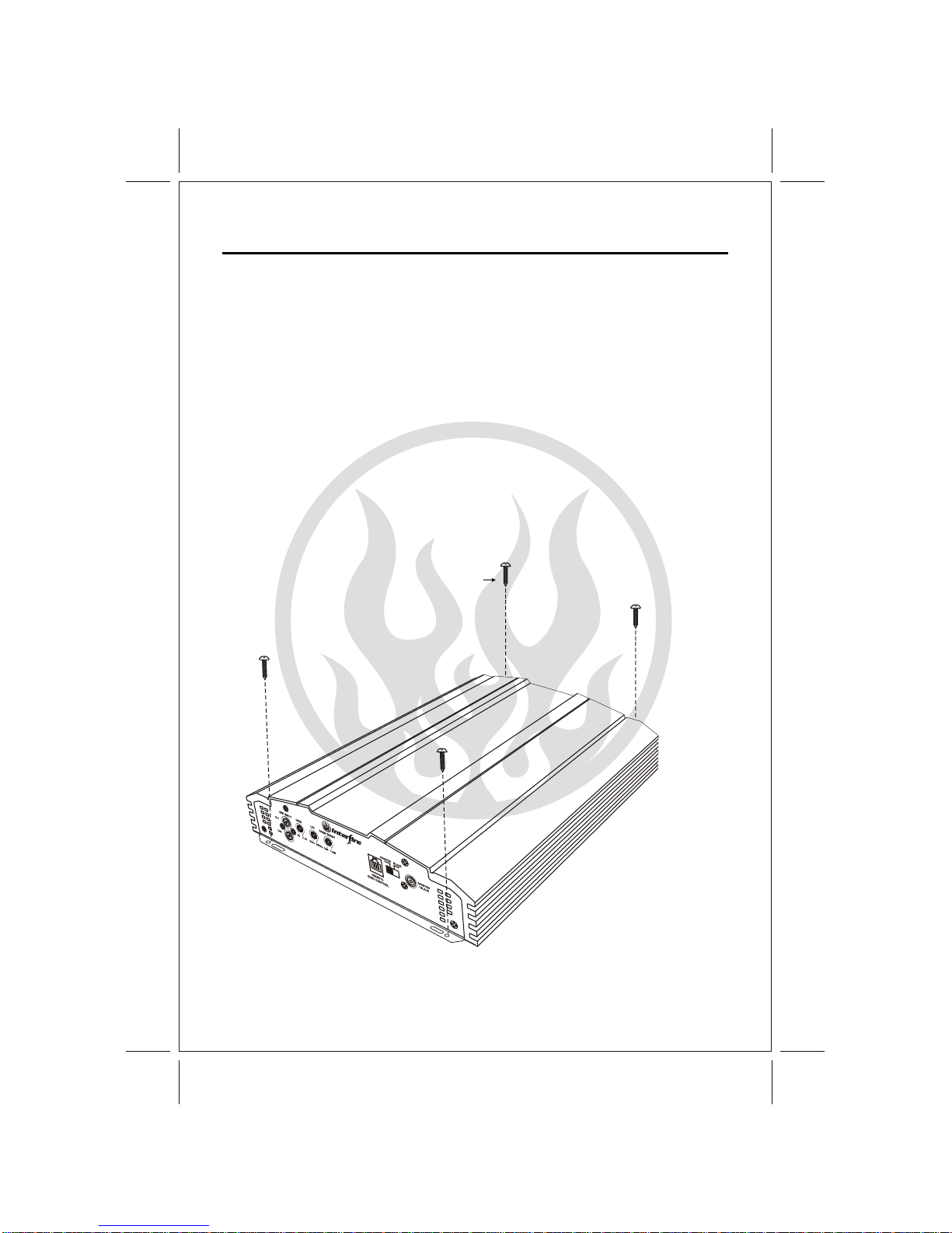
INSTALLATION
1. Afterreading precaution, decidewhere you aregoing to installthe unit.Also, see Fig.1.
2. Once thelocation has beendetermined, place theamplifier into position.Using a felttip
pen or pencilmark the fourholes to bedrilled for mounting.NEVER use theamplifier as
a template for drilling. It is very easy to damage the amplifier surface in this manner.
3. Remove amplifier. Drill four3.5 m/m holesinto mounting surface.If you wantto mount
4. If possible,test the system to ensure itis operating correctly before final mounting of
5.
FIG.1
2
MOUNTING:
Mount the amplifierusing the supplied4 self tapping screws.
the amplifier to MDF or wood panel, drill four 3.0m/m diameter holes into mounting surface.
the amplifier.
INSTALLATION DIAGRAM
Self Tapping Screws
FUSE
30A 30A 30A
SPEAKER
G1-2000
digital mono block AMPLIFIER
POWER
REM GNDB+
FUSE
30A 30A 30A
SPEAKER
G1-2000
digital mono block AMPLIFIER
POWER
REM GNDB+
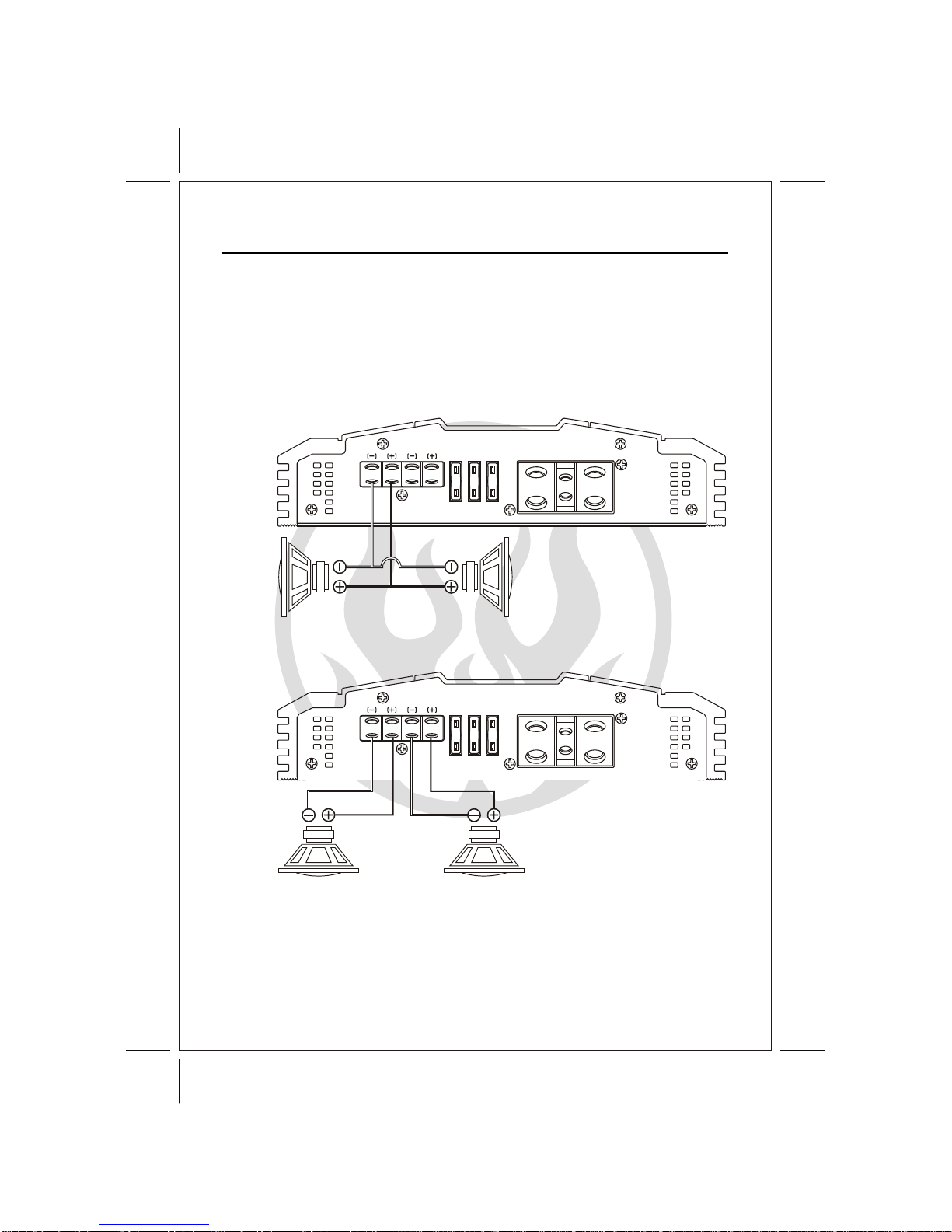
The Class "D" amplifier is a SINGLE CHANNEL dedicated subwoofer amplifier. Unlike
other amplifiers, the Class "D" operates as a single channel and cannot be bridged.
Don't be fooled by the outputs. Two outputs are used strictly for convenience and are
paralleled internally on the amplifier. This means that if both outputs are used with one
driver each, the amplifier sees the same load as if the same drivers are connected to
4OHM
SUBWOOFER
4OHM
SUBWOOFER 4OHM
SUBWOOFER
3
4OHM
SUBWOOFER
only one outputterminal. See diagrambelow.
SPEAKER WIRING
In both diagrams, the amplifiersees a 2 ohm load.

LINE INPUT
CH1
CH2
GAIN LPF
6V 0.2V 50Hz 250Hz
BASS BOOST SLAVEMASTER
MASTER
/SLAVE
REMOTE
GAIN CONTROL
LINE INPUT
CH1
CH2
GAIN LPF
6V 0.2V 50Hz 250Hz 0dB 12dB
BASS BOOST SLAVEMASTER
MASTER
/SLAVE
REMOTE
GAIN CONTROL
4
FROM
RADIO
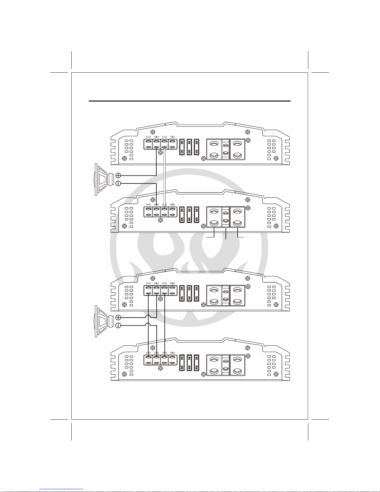
MONO BRIDGED
WIRING SUBWOOFERS(DUAL AMPS)
When using dual amplifiers to power one subwoofer, the Positive terminal of the Subwoofers
voice coil is connected the positive terminal of the MASTER Amplifier and the Negative terminal
of the Subwoofers voice coil is connected to Positive terminal on the SLAVE Amplifier. This
procedure will allow the total power of both amplifiers to be added together and act like a single
powerful amplifier. Please check that your subwoofer power handling capabilities are not exceeded
CAUTION
Always check your speaker load with a multi-meter before hooking up to the amplifier. These
digital amplifiers are only 1ohm stable. AnyImpedance (load) smaller than 1ohm will damage
the amplifier. SuchDamage is not covered underwarranty either, sopay strict attention towhat
when hooking two amplifiers toit.
connections are madeto the amplifier.
Master
Amplifier
Slave
Amplifier
MASTER SLAVE
MASTER SLAVE
SPEAKER WIRING
0dB 12dB
FUSE
30A 30A 30A
SPEAKER
G1-2000
digital mono block AMPLIFIER
POWER
REM GNDB+
FUSE
30A 30A 30A
SPEAKER
Gd-1000
digital mono block AMPLIFIER
POWER
REM GNDB+
FUSE
30A 30A 30A
SPEAKER
Gd-1000
digital mono block AMPLIFIER
POWER
REM GNDB+
FUSE
30A 30A 30A
SPEAKER
G1-2000
digital mono block AMPLIFIER
POWER
REM GNDB+
5
Master
Amplifier
Slave
Amplifier
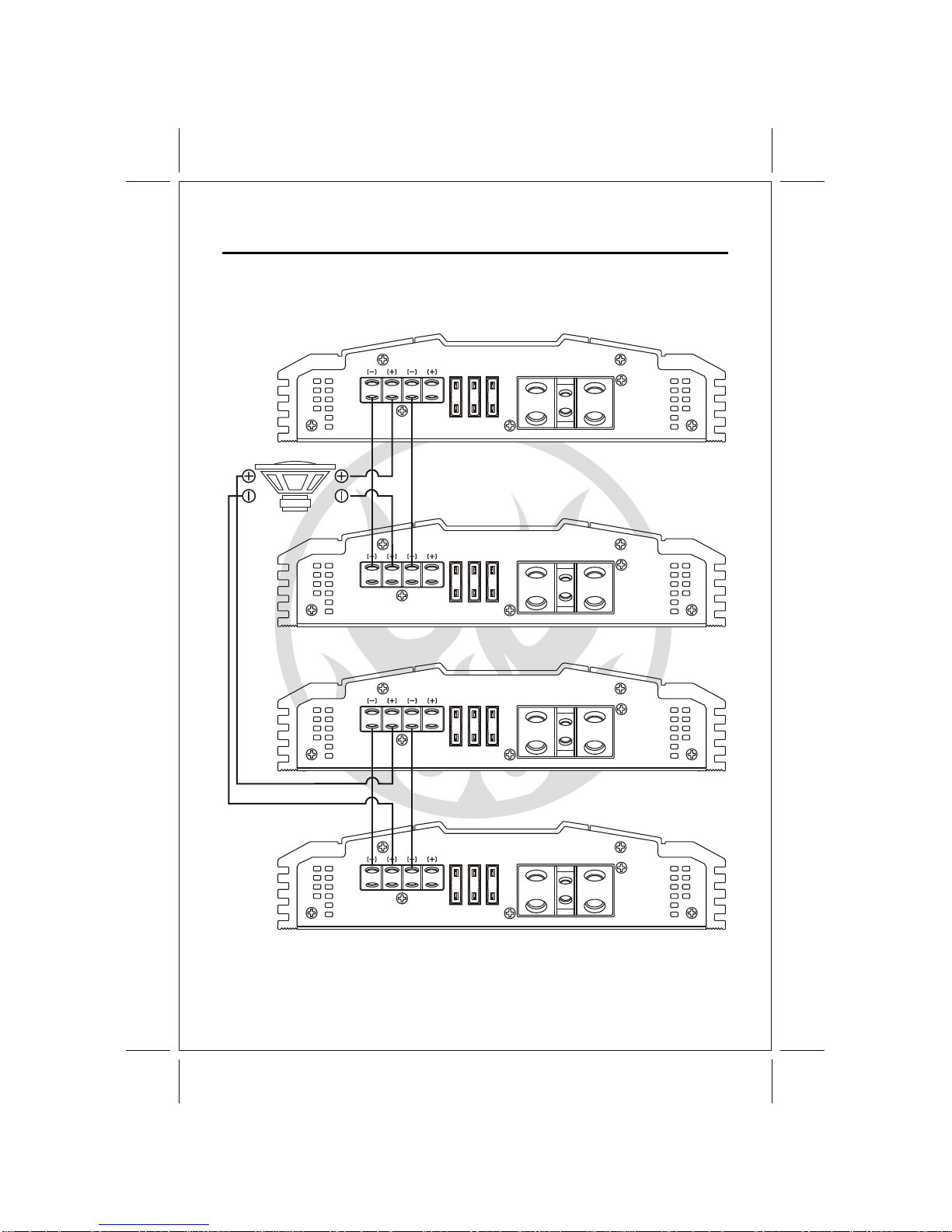
(OPTION) TWOAMPLIFIER/ ONESUBWOOFER (SINGLEVOICE COIL)CONFIGURATION
CHASSIS GROUND
REMOTE TURN ON
BATTERY VIA FUSE
Using a lead wire of 8 gauge or
bigger connect from the master
Amp's negative(-) speaker
terminal to the slave Amp's
negative(-) speaker terminal.
Master
Amplifier
Slave
Amplifier
Recommend : Competition Only
MONO BRIDGED
SPEAKER WIRING
FUSE
30A 30A 30A
SPEAKER
G1-2000
digital mono block AMPLIFIER
POWER
REM GNDB+
FUSE
30A 30A 30A
SPEAKER
G1-2000
digital mono block AMPLIFIER
POWER
REM GNDB+
FUSE
30A 30A 30A
SPEAKER
G1-2000
digital mono block AMPLIFIER
POWER
REM GNDB+
FUSE
30A 30A 30A
SPEAKER
G1-2000
digital mono block AMPLIFIER
POWER
REM GNDB+
MONO BRIDGED
(OPTION) FOURAMPLIFIER/ ONESUBWOOFER (DUALVOICE COIL)CONFIGURATION
6
Master
Amplifier
Slave
Amplifier
Master
Amplifier
Slave
Amplifier
Voice
Coil1 Voice
Coil2
SPEAKER WIRING

7
The proper wire size is very important for an amplifier of this power level. Because the
Class "D" amplifier is capable of drawing in excess of 90 amperes,4 gauge wire is
recommended for lengths up to twenty feet. if a longer length is needed, a larger gauge
Amplifier power wire should be wired directly to the battery using the wire requirements
listed above. Start at the amplifier and run the power wire through the vehicle to the
battery. The use of grommets is recommended when passing the power wire through
any metal wall. Avoid sharp corners or sharp body parts that may easily cut through the
insulation on the wire. Avoid running the power wire over engine components and near
heater cores. Use an inline fuse to eliminate the risk of a fire caused by a short in your
power wire. Connect the fuse holder as close to the battery positive as possible. For
most applications, an 80 ampere Maxi fuse or comparable ANL wafer fuse can be used.
Now connect the wire to the battery, but remember to leave the fuse out until all other
POWER SUPPLY CONNECTIONS
RECOMMENDED POWERWIRE
POWER
The Class "D" amplifier is designed to work within 10 to 16 volts DC. Before any wires
are connected, the vehicle's electrical system should be checked for correct voltage
supply withthe helpof a voltmeter. First checkthe voltageat thebattery terminalswith
the ignition in the off position. The voltmeter should read no less than 12volts. Next,
check the battery with the engine running between 1500 and 2000 rpm.The voltmeter
should nowread between 13.5 and14.5 volts. If yourvehicle's electrical system Isnot
up tothese specifications,we recommendhaving itchecked byan automotivemechanic
before further installation.
wire maybe necessary.
wire connectionsare mode.
When grounding your amplifier, locate a metal area close to the amplifier that is a good
source of ground ( preferably the floor ).Once again, investigate the area you wish to use
for electrical wires, vacuum lines, and brake or fuel lines. Using either a wire brush or
sandpaper eliminate unwanted paint to supply a better contact for your ground. Use the
same gauge wire for ground as you did for the power. Terminate the ground wire using the
correct size ring terminal and attach it to the bare metal using a nut and bolt. It is important
for this connection to be solid. To complete the job, spread silicon over the screw and bare
GROUND
REMOTE TURN-ON
metal to preventrust and possiblewater leaks.
In between the power and ground is a remote turn-on terminal. This terminal must be
connected to a switched +12volt source. Typically, remote turn-on leads are provided
at the sourceunit that willturn on andoff theamplifier in correspondencewith the source.
If a radiodoes not havea remote turn-on,then a powerantenna wire maybe used. Yet,if
neither of these leads are available at the source, a switched +12 volt supply must be
supplied. Run aminimum of 18-gaugewire from theamplifier location tothe source ofthe
switched +12 voltlead. If possible,route this wireon the sameside of thevehicle as your
power wire. Connectthe source remoteoutput wire tothe REM terminalon the amplifier
using a 3mm screw key. Cut the remote wire to length. Strip approximately 1/2 inch of
insulation from theend of thewire and insertinto the terminal. Tighten thescrew securely.

LINE INPUT
CH1
CH2
GAIN LPF
6V 0.2V 50Hz 250Hz 0dB 12dB
BASS BOOST SLAVEMASTER
MASTER
/SLAVE
REMOTE
GAIN CONTROL
8
1 2 3 4 5 6 7
1. RCAInput Jacks 2. Input Level Control 3. Low PassFrequency
4. Bass Boost
5. Remote ControlJack 6. Master/SlaveSwitch 7. SlaveInput Jack
OPERATION
Control and Crossover
1. RCAInput Jacks - Lowlevel-high impedance inputs. Usehigh quality RCAcables designed
for mobile applications.
2. Input Level Control- Adjustthe input level forthe marked channels. Turn clockwise to
increase the level, counterclockwiseto decrease.Amplifiers will run coolerand produce
less system noise atlower level settings.
3. Low Pass Frequency- Adjustthe crossover frequency byturning clockwise to setto a higher
frequency, counterclockwiseto set to alower frequency.
4. Bass Boost -Adjust thesub boost level ofthe selected frequency outputfrom 0dB to 12dB.
5. Remote Control Jack- For connecting theremote control module tothe amplifier.
6. Master/Slave Switch -Select the remote levelcontrol or the on-boardlevel control as the
master control.
7. Slave Input Jack- Used to connectto another amplifier whenbridging 2 amps together.
The Slave modebypasses normal input jacksand controls.

9
FRONT/REAR PANEL
G1-1200/2000/3000 front
G1-1200 REAR
G1-2000 REAR
G1-3000 REAR
FUSE
25A 25A 25A
SPEAKER
Gd-1500
digital mono block AMPLIFIER
POWER
REM GNDB+
FUSE
30A 30A 30A
SPEAKER
Gd-2000
digital mono block AMPLIFIER
POWER
REM GNDB+
SPEAKER POWER
REM GNDB+
Gd-3000
digital mono block AMPLIFIER
LINE INPUT
CH1
CH2
GAIN LPF
6V 0.2V 50Hz 250Hz 0dB 12dB
BASS BOOST SLAVEMASTER
MASTER
/SLAVE
REMOTE
GAIN CONTROL

10
This section providesyou with acatalog of amplifiersymptoms and theirprobable causes
and solutions. Beforeyou consult thislisting, make surethe vehicle's electricalsystem is
working properly byverifying that otherelectrical items (e.g. headlights, windows,etc.)
Still function correctly.
TROUBLE SHOOTING GUIDE
NoAudio Low or N.C Remote
Turn-on connections
Blown Fuse
Power wires not connected
Blown or non speakers
connected
Check remote turn-on voltage at
amp and head unit
Replace with new fast-blow fuse
Check butt splices or solder joints
Check ground and battery
connections
Use VOM or DVM to measure speaker
coil
impedance; check speaker wiring
connections
SOLUTIONPROBABLE CAUSE
SYMPTOM
See adjustment procedure and check
each step;
Inspect each speaker for damage
and repair or replace suspected
component
Refer to head unit owner's manual
Input Sensitivity not set
properly
or damaged speaker cones
Low turn-on voltage
DistortedAudio
Audio Level Low Mute circuit on head
unit is on. Check electrical system for low
voltage;
Check ground connection
Audio Lacks Speakers wired with wrong
polarity, causing
cancellation of bass
frequencies
Check polarity of wires from
amplifiers to each speaker as defined
by the system design
Check battery voltage at amplifier
during operation
External Fuse
Blowing Incorrect wiring or short
circuit Refer to electrical installation and
check each installation step
Whining noise
on audio with
engine running
Amplifier is picking
up alternator noise Install an in-line noise filter on the
head unit's power wire; Check
alternator routing diodes or voltage
regulator for proper operation. Check
all grounds , battery voltage, and
RCAcables
Ticking noise on
audio with
engine
running
Amplifier is picking up
radiated spark noise Check RCAaudio cable; Install an
in-line noise filter on the head unit's
power wire. Check spark plug wires.

11
NOTE : Specifications & design subject to change without notice
for improvements.
SPECIFICATION
AMPLIFIER
G1-1200 G1-2000 G1-3000
RMS POWER / 1 ohm @ 1% T.H.D 1200W x 1 2000W x 1 3000W x 1
750W x1 1000W x 1 2000W x 1
400W x1 500W x1 1000W x 1
90% 90% 90%
79% 79% 79%
10Hz ~ 250Hz 10Hz ~ 250Hz 10Hz ~ 250Hz
>100dB >100dB >100dB
150 150 150
200mV ~ 6V 200mV ~ 6V 200mV ~ 6V
20K Ohms 20K Ohms 20K Ohms
75Amp 90 Amp Need External Fuse/
Minimum 180 Amp
245 x 55 x 320 245 x 55 x 350 245 x 55 x 420
50 ~250Hz 50 ~250Hz 50 ~ 250Hz
24dB 24dB 24dB
0dB ~ 12dB 0dB ~ 12dB 0dB ~ 12dB
2 ohms @ 0.05% T.H.D
4 ohms @ 0.05% T.H.D
Efficiency / Typical @ 4 ohms
MIN RATE @ 1 ohm
Signal To Noise Ratio ('A' WTD)
Damping Factor
Input Sensitivity
Input Impedance
Circuit Breaker
Dimensions (W x H x D) mm
Variable Low Pass Filter
X-Over Slope
Variable Bass Boost
Bandwidth ±1dB


appliedtoproducts. (Interfire Audio willnot be
WARRANTY
WARRANTY LIMITATIONS
The following is NOT covered under Interfire
Audio's warranty program:
NOTICE: Products shipped withouta valid RA# will berefused and shippedback.
manual
lightning, etc.)
Custom finishes)
Product with defaced, altered or removed
serial numbers (no valid, legible serial No.
= no warranty).
or missing magnets.
1.
3.
4.
5.
6.
7.
8.
WARRANTY TERMS
(Effective January 01, 2010)
These terms supersede all prior published
warranty terms
Interfire Audio products are warrantied against
defects in materials and workmanship for a
period of One (1) Year from the original date of
purchase.
Products found to be defective during the
warranty period will be repaired or replaced
(with a product deemed to be equivalent) at
Interfire's discretion.
Note: Products purchased from unauthorized
dealers are not covered under warranty. Ask
your dealer for details on warranty limitations.
INTERNATIONAL WARRANTIES:
Products purchased outside the United States
of America are covered only by that country's
distributor and not by Interfire Audio, Inc.
IF YOU NEED SERVICE ON YOUR
INTERFIRE AUDIO PRODUCT:
and box.
9. Product damaged cosmeticallydue to
improper handling ornormal wear and
tear Including Freight damage. Besure
to package all returns in its packing material
10. Installation and shipping costs associated
with removing, re-installing or shipping the
product to Interfire Audio for warranty service
Interfire Audiodealer. (Thewarranty is
Product owned by anyone other than the
original purchaser froman authorized
NOT transferable and willnot apply to
products purchased from unauthorized
dealers.)
orspiders).
2. Speakerproductsthathave beenover-
powered,causingthermal(burnt voice coil)
and/ormechanicalfailure(ripped surrounds
Product that hasNOT been installed
according to the instructions in the owner's
Product in which repair and/or modification
has been attempted by unauthorized parties
Product damaged in an accident, due to
criminal activity (attempted theft, gunshot
damage, etc.) or by "acts of God" (flooding,
Product that has been physically damaged
abusedand/oraltered. Includingbent frames
Customfinishesor othercosmetic treatments
responsible for restoring or maintaining any
sales receipt.) Direct returns from consumers
by proof of purchase (a copy of theoriginal
1-877-90-AUDIO to obtain an RA #(Return
Authorization number). All warranty returns
should be sent to INTERFIRE AUDIO freight
prepaid through an authorized INTERFIRE
AUDIO dealer andmust be accompanied
or non-authorized dealerswill be refused
unless specifically authorized by INTERFIRE
AUDIO with avalid return authorization
Please call InterfireCustomer Service at
number. Warranty expiration onproducts
returned without proof ofpurchase will be
determined from themanufacturing date
code. Coverage may be invalidated as this
date is previous topurchase date. Return
only defective components. Non-defective
items received will be returned freight-collect.
Customer is responsible for shipping charges
and insurance insending the productto
INTERFIRE AUDIO.Freight damage on
returns is notcovered under warranty.
Always include proofof purchase (sales
receipt).

Printed in PRC
Interfire Audio, Inc.
Santa Fe Springs, CA 90670
www.interfireaudio.com
This manual suits for next models
2
Table of contents
Other Interfire Car Amplifier manuals


