International Harvester Company Cub Lo-Boy C-60 User manual
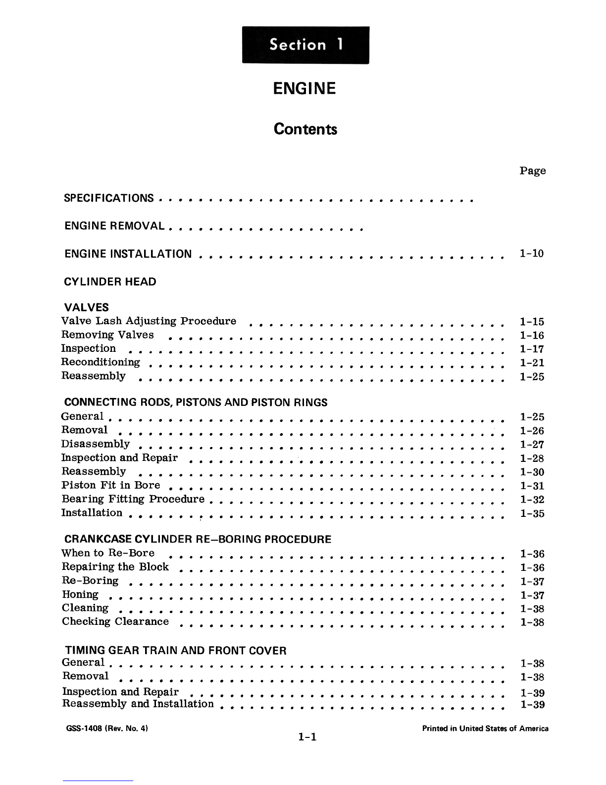
ENGINE
Contents
Page
SPECIFICATIONS.
ENGINEREMOVAL.
1-10
ENGINEINSTAllATION.
CYLINDER HEAD
1-151-161-171-21
1-25
VALVES
Valve Lash Adjusting Procedure.Removing Valves.Inspection.Reconditioning.Reassembly.
CONNECTING RODS, PISTONS AND PISTON RINGSGeneral.
Removal. Disassembly.Inspection and Repair.Reassembly.Piston Fit in Bore.Bearing Fitting Procedure.Installation. ~ 1-251-261-271-281-301-31
1-32
1-35
1-361-36
1-37
1-371-38
1-38
CRANKCASE CYLINDER RE-BORING PROCEDURE
When to Re- Bore.Repairing the Block.Re-BoringHoning.Cleaning.Checking Clearance.
1-38
1-38
1-39
1-39
TIMING GEAR TRAIN AND FRONT COVERGeneral.
Removal.Inspection and Repair.Reassembly and Installation.
GSS-1408(Rev. No.4) Printed in United States of America
1-1

CAMSHAFT
General.Removal. "Inspection and Repair.Installation.
1-42
1-42
1-421-43
CRANKSHAFT AND MAIN BEARINGSGeneral.
Removal.Inspection and Repair.Installation. 1-45
1-45
1-46
1-47
1-501-511-51
1-52
1-52
1-531-54
LUBRICA TI NG 01 L PUMP.GeneralDescription.Oil Pump.Pressure Regulator Valve.Removal and Disassembly.Inspection and Servicing.Reassembly.
COOLING SYSTEM
General Description and Operation.Removal and Disassembly.Inspection and Repair.Fan Service.Reassembly and Installation. 1-55
1-561-571-571-58
TROUBLE SHOOTING
TUNE-UP
GSS-1408(Rev. No.4) Printed in United States of America
1-2

General
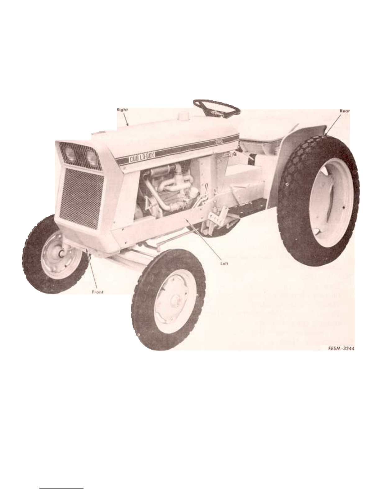
Model. C-60
Number of cylinders. ~ 4
Boreandstroke-inches 2-5/8 x 2-3/4
Displacement-cubicinches 59.5
Engine rpm (governed) 154 184 185
Low idle.! 25 475 600
High idle.! 25 2420 2510
Rated load.! 10 2200 2300
Compression ratio. 7.5:1
Compression pressure at cranking speed -psi. 130
Firing order. 1-3-4-2
Ignition timing
Highidle 16oBTDC
400 rpm TDC
Distributor point gap -inch. 020
Spark plug gap-inch 023
NOTE: Proper ig1lition timing at high idle is essential for best ~rformance and engine
life. Therefore, tile distributor should be set to give tile ~ timing at high idle. Any
variance tilat may exist then will occur at the low idle end of the advance curve.
Crankcase
Cylinder bore -inches. 2.625 -2.627
Crankshaft. and Main Bearings
Crankshaft
Type Counterbalanced
Numberofmainjournals 3
Main journal diameter -inches. 1.623 -1.624
Crankpin diameter -inches. 1.498 -1.499
Main Bearings
Type Tri-metal,precision
Runningclearance-inch .002- .003
Thrust bearing location. Center
Thrust bearing side clearance -inch. 004 -.008
Bearing aD and spread
Frontandrear-inches 1.777+.020
Center-inches 1.777 +.002 to .015
Camshaft
Drive. Helical gear
Cam lobe lift (total) -inch. 232.! .002
Journal diameter
Front-inches 1.871-1.872
Center-inches 1.746-1.747
Rear -inch. 872 -.873
Crankcase bearing bore diameters
Front -inches. 1.8740 -1.8755
Center -inches. 1.7490 -1.7505
Rear -inch. 8740 -.8755
GSS-1408 (Rev. No.2) Printed in United States of America
1-4

Camshaft
-Continued
Thrusttakenby Thrustplate
Number of bearings. 3 (bored in crankcase)
Bearing running clearance
Front and center -inch. 002 -.0045
Rear-inch .001-.0035
End clearance -inch. 003 -.012
Connecting Rods
Type. I-Beam
Side clearance -inch. 005 -.012
Bearing running clearance -inch. 002 -.003
Bearing type
Upper end. Bronze bushing
Lower end. Tri-metal, precision
Bearing OD and spread -inches. 1.625 + .025
Piston pin bushing ill -inch (installed) 6879 -.6882
Pistons
Type Camground
Material.. Aluminum alloy
Overall length -inches. 2.875
Diameter -inches. 2.6230 -2.6234
*S1drt clearance, bottom -inch. 0016 -.0024
(measured at 900 from pin hole)
Number of rings per piston. 3
Piston pin hole bore -inch. 6877 -.6880
Width of ring groove -inch
Topcompression. 0955 -.0965
Second compression. 0955 -.0965
Oil control. 1880 -.1890
Ring clearance in groove -inch
Top compression. '. 0020 -.0035
Second compression. 0020 -.0040
Oil control. 0015 -.0030
Full floating
.6875 -.68762.185
-2.195
.010 -.030
.0003 -.0007
.0001- .0005
Piston Pins \
Type. ~Diameter-inchLength -inches.Clearance between end of pin and retainer ring -inch.Clearance in rod bushing-inch .
Clearance in piston -inch.
*See"Piston Fit in Bore", page 1-31.
1-5
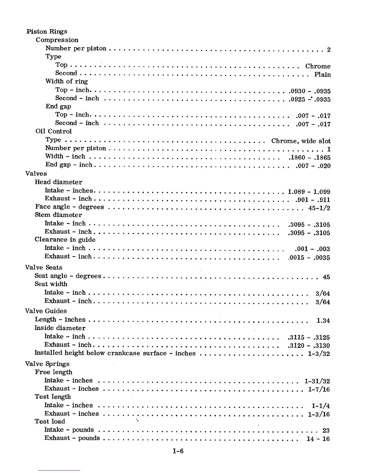
Piston Rings
Compression
Number per piston. 2
Type
Top Chrome
Second Plain
Width of ring
Top -inch. 0930 -.0935
Second-inch 0925-..0935
End gap
Top -inch. 007 -.017
Second-inch. 007 -.017
Oil Control
Type.NumberperpistonWidth -inch.End gap -inch. Valves
Head diameter
Intake -inches. 1.089 -1.099
Exhaust -inch. 901 -.911
Face angle -degrees. 45-1/2
Stem diameter
Intake-inch .3095-.3105
Exhaust-inch .3095-.3105
Clearance in guide
Intake-inchExhaust -inch.
,
Chrome, wide slot,
1,
1860 -.1865,
007 -.020
.001- .003.0015
-.0035
Valve Seats
Seat angle -degrees. 45
Seat width
Intake-inch 3/64
.Exhaust-inch 3/64
Valve Guides
Length-inches 1.34
Inside diameter
Intake -inch. 3115 -.3125
Exhaust-inch .3120- .3130
Installed height below crankcase surface -inches. 1-3/32
Valve Springs
Free length
Intake -inches. 1-31/32
Exhaust-inches 1-7/16
Test length
Intake-inches 1-1/4
Exhaust -inches. 1-3/16
Test load "
Intake-pounds 23
Exhaust-pounds 14-16
1-6
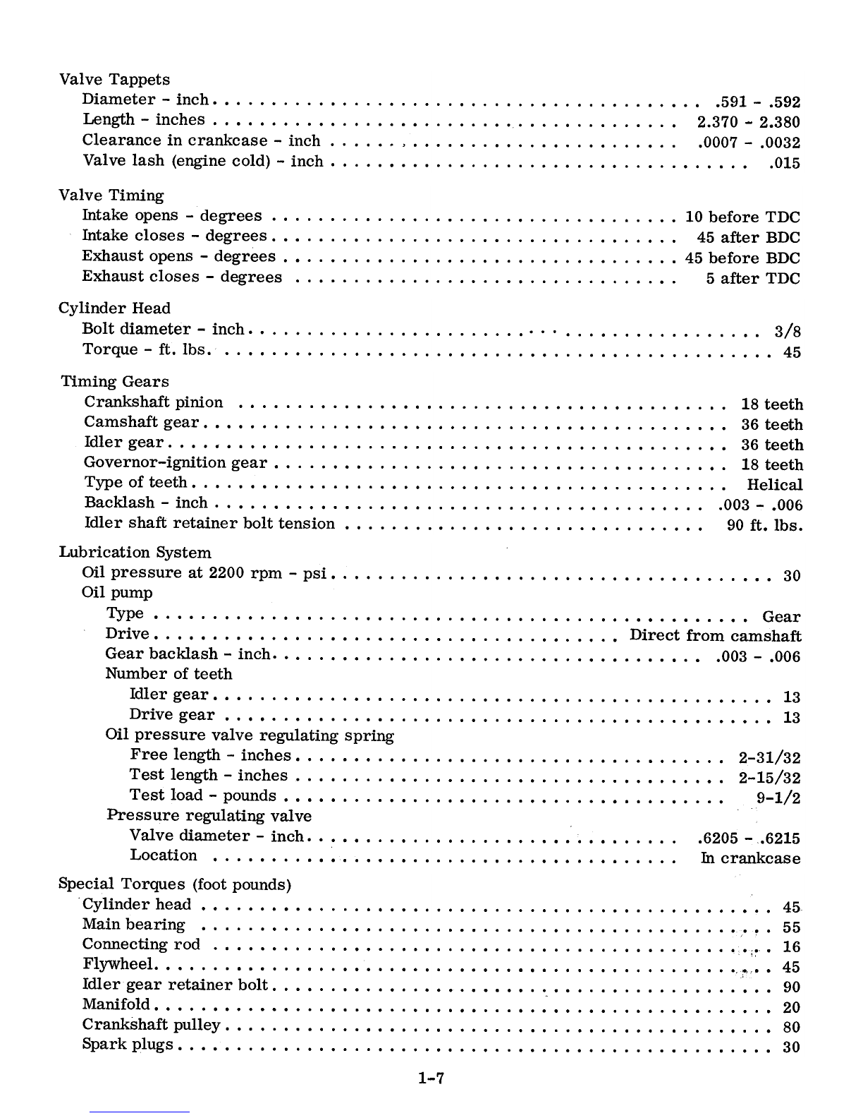
Valve Tappets
Diameter-inch .59.1-.592
Length -inches. 2.370 -2.380
Clearance in crankcase -inch. , 0007 -.0032
Valvelash(enginecold)-inch .0.15
Valve
Timing
Intakeopens-degrees 10beforeTDC
Intakecloses-degrees 45afterBDC
Exhaustopens-degrees 45beforeBDC
Exhaustcloses-degrees 5afterTDC
Cylinder Head
Boltdiameter-inch 3/8
Torque-ft.lbs. 45
Timing Gears
Crankshaft pinion. 18 teeth
Camshaft gear. 36 teeth
Idler gear. 36 teeth
Governor-ignitiongear 18teeth
Type of teeth. Helical
Backlash -inch. 003 -.006
Idler shaft retainer bolt tension. 90ft. lbs.
Lubrication System
Oil pressure at 2200 rpm -psi. 30
Oil pump
Type. Gear
Drive Direct from camshaft
Gear bacldash -inch. 003 -.006
Number of teeth
Idlergear 13
Drive gear. 13
Oil pressure valve regulating spring
Free length -inches. 2-31/32
Testlength-inches 2-15/32
Test load -pounds. 9-1/2
Pressure regulating valve
Valve diameter -inch. 6205 -.6215
Location. In crankcase
Special Torques (foot pounds)
Cylinder head 45
Main bearing. ~ .55
Connectingrod ;~. 16
Flywheel ;0"..45
Idlergearretainerbolt 90
Manifold 20
Crankshaft pulley 80
Sparkplugs 30
1-7

ENGINE REMOVAL
1. Disconnectthe battery ground
cable at the battery.
2. Drain the crankcase oil and re-
move the drain plug in the water inlet
elbow and drain the coolant.
3. Removethe hoodand side sheet
sections.
4. Shut off the fuel at the fuel strainer
(3) and disconnect the fuel line (4) from
the fuel strainer and the carburetor (5).
5. Removethe fuel tank (2).
GSS-1408 (Rev. No. 41 Printed in United States of America
1-8
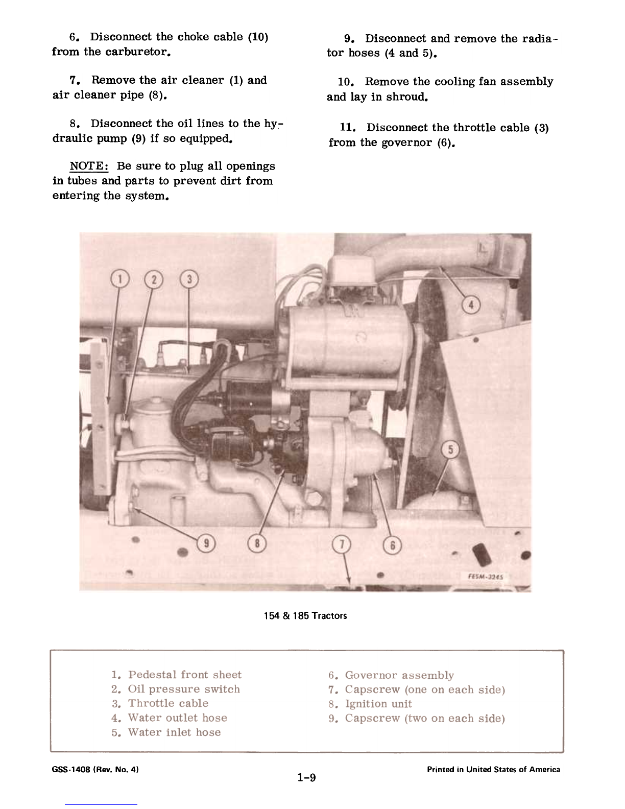
6. Disconnectthe chokecable (10)
from the carburetor. 9. Disconnectandremove the radia-
tor hoses (4and5).
7. Removethe air cleaner (1)and
air cleaner pipe (8). 10. Removethe cooling fan assembly
and lay in shroud.
8. Disconnect the oil lines to the hy.-
draulic pump (9) if so equipped. 11. Disconnect the throttle cable (3)
from the governor (6).
NOTE: Be sure to plug all openings
in tubes and parts to prevent dirt from
entering the system.
154 & 185 Tractors
685-1408 (Rev. No. 41 Printed in United States of America
1-9
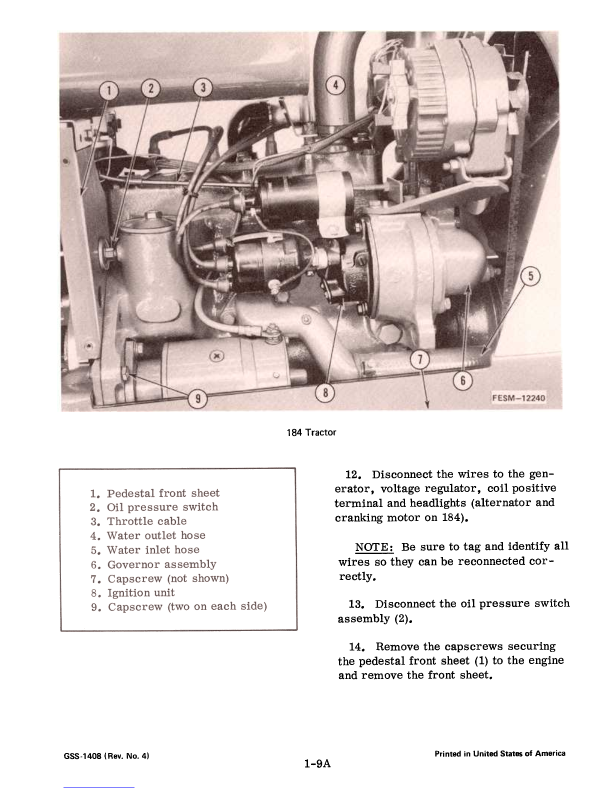
184 Tractor
12. Disconnectthe wires to the gen-
erator, voltage regulator, coil positive
terminal andheadlights (alternator and
cranking motor on 184).
NOTE: Be sure to tag and identify all
wires so they can be reconnected cor-
rectly.
13. Disconnectthe oil pressure switch
assembly (2).
14. Remove the capscrews securing
the pedestal front sheet (1) to the engine
and remove the front sheet.
Printed in United States of America
GSS-140B(Rev. No.4) 1-9A
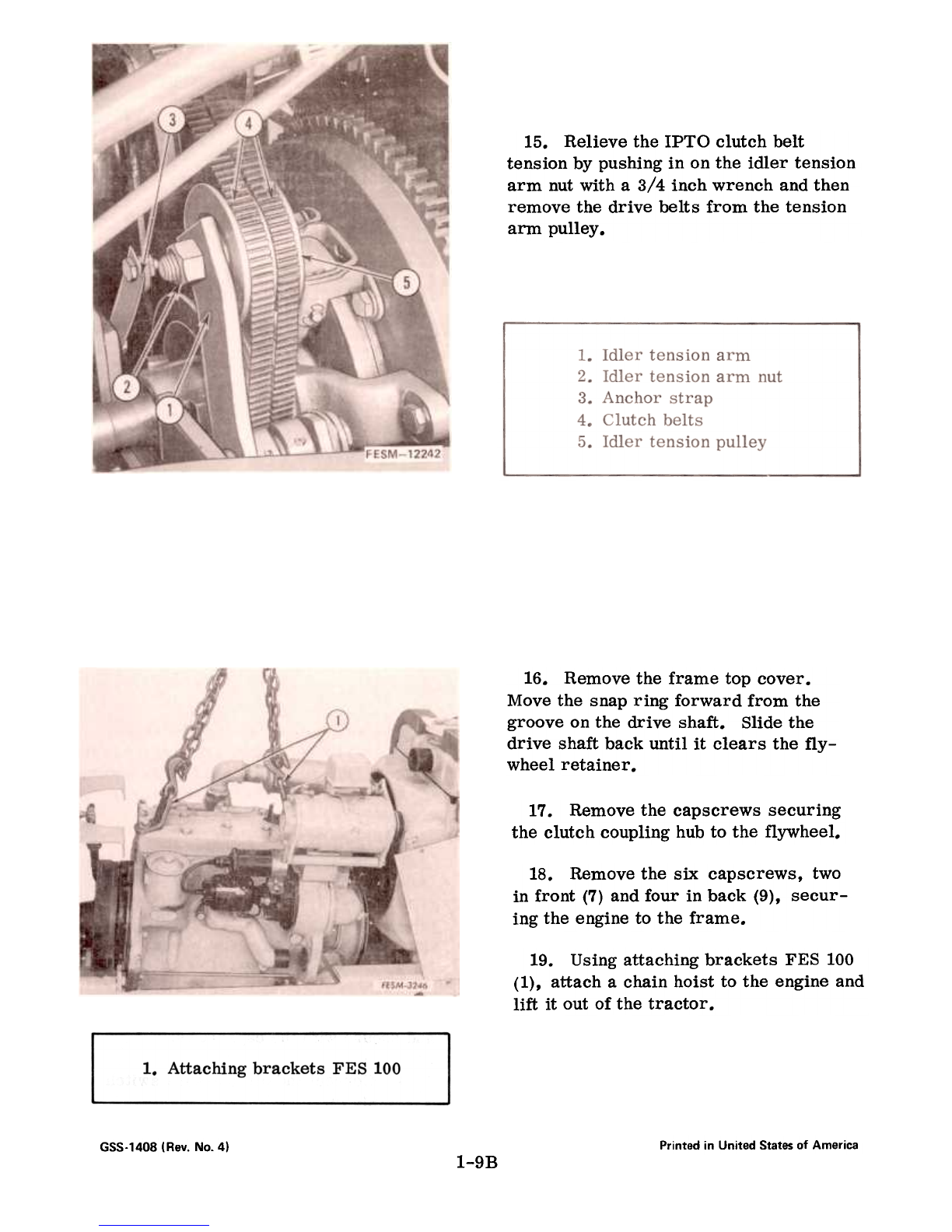
15. Relieve the IPTO clutch belt
tension by pushing in on the idler tension
arm nut with a 3/4 inch wrench and then
remove the drive belts from the tension
arm pulley.
16. Remove the frame top cover.
Move the snap ring forward from the
groove on the drive shaft. Slide the
drive shaft back until it clears the fly-
wheel retainer.
17. Remove the capscrews securing
the clutch coupling hub to the flywheel.
18. Remove the six capscrews, two
in front (7) and four in back (9), secur-
ing the engine to the frame.
19. Using attaching brackets FES 100
(1), attach a chain hoist to the engine and
lift it out of the tractor.
1. Attaching brackets FES 100
Printed in United States of America
GSS-1408 (Rev. No.4) 1-9B
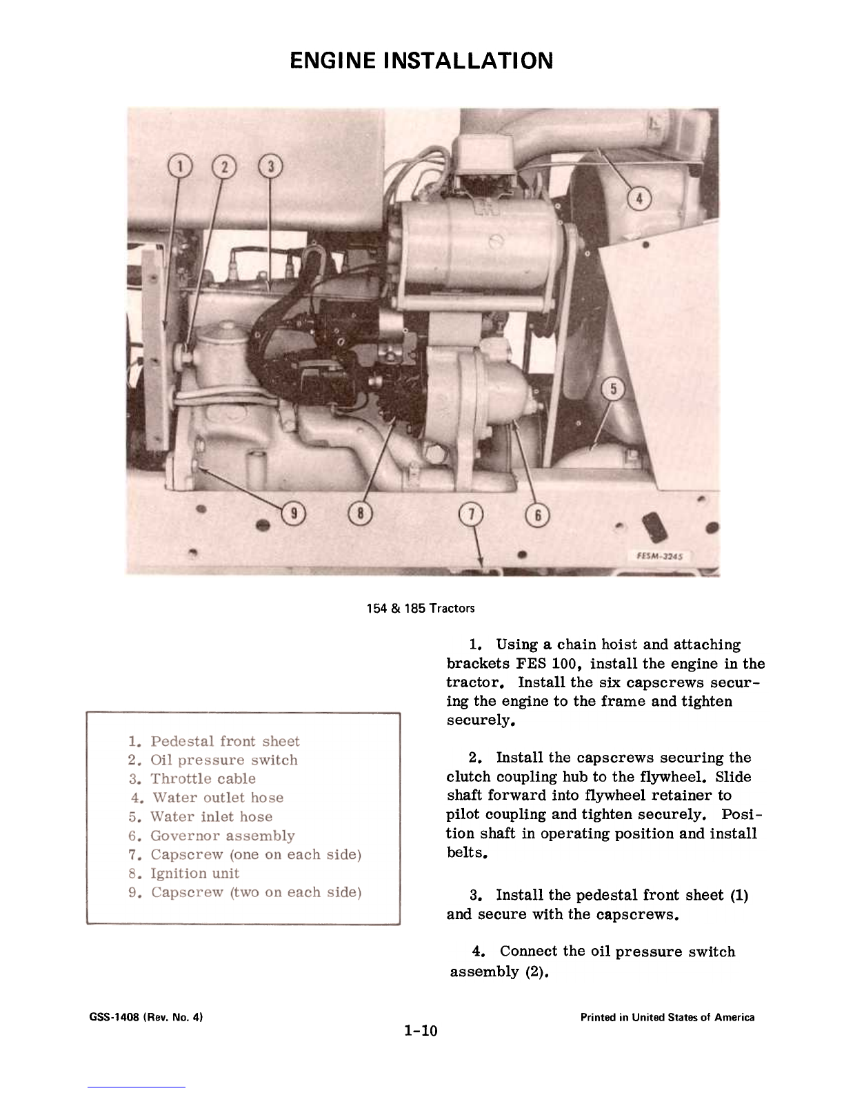
ENGINE INSTALLATION
154 & 185 Tractors
1. Using a chain hoist and attaching
brackets FES 100, install the engine in the
tractor. Install the six capscrews secur-
ing the engine to the frame and tighten
securely.
2. Install the capscrews securing the
clutch coupling hub to the flywheel. Slide
shaft forward into flywheel retainer to
pilot coupling and tighten securely. Posi-
tion shaft in operating position and install
belts.
3. Install the pedestal front sheet (1)
and secure with the capscrews.
4. Connectthe oil pressure switch
assembly (2).
GSS-1408 (Rev. No.4) Printed in United States of America
1-10
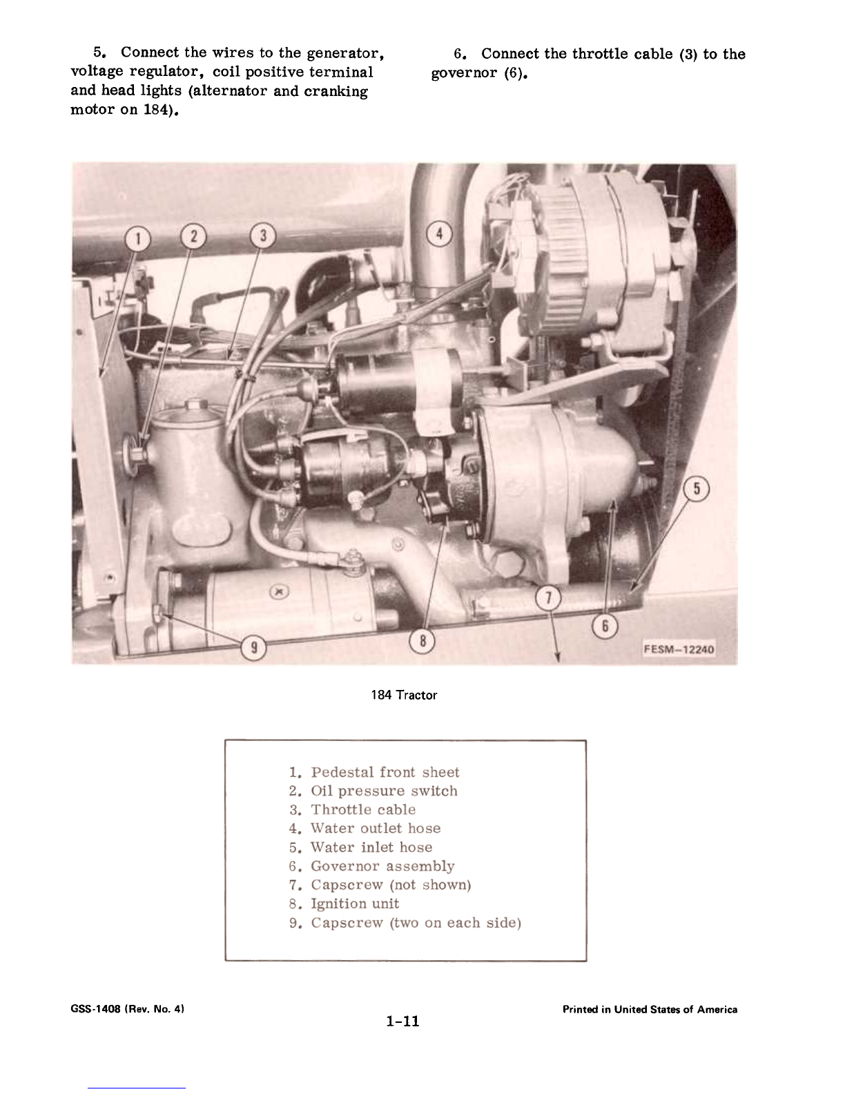
5. Connectthe wires to the generator,
voltage reg1l1ator, coil positive terminal
andheadlights (alternator andcranking
motor on184).
6. Connectthe throttle cable (3) to the
governor (6).
184 Tractor
GSS-1408 (Rev. No.4) Printed in United States of America
1-11

6SS-1408 (Rev. No.4) Printed in United States of America
l-llA
7. Install the cooling fan assembly (11).
Be sure the fanblades clear the radiator
shroud. If clearance is not s~ficient, re-
position fan shroud.
8.
Connectthe radiatorhoses.
9. Install the air cleaner (1)and air
cleaner pipe (8). Be sure air cleaner
pipe connectionsare goodto prevent dirt
from entering the engine.
10. Connectthe oil lines to the hydrau-
lic pump(9), (if equipped).
11. Connectthe chokecable (10)to the
carburetor (5).
12. Install the fuel tank (2) and con-
nect the fuel line (4) to the carburetor and
the fuel strainer (3).
13. Install the frame top covert side
sheets andhood.
14. Fill the crankcase with oil andthe
radiator with coolant. Refer to the
Operator's Manual.
Connect the battery ground cable.
15.
GSS-1408 (Rev. No.4) Printed in United States of America
1-liB

THIS PAGE INTENTIONALL V BLANK
Printed in United States of America
GSS-1408 (Rev. No.4) 1-12
CYLINDER
HEAD
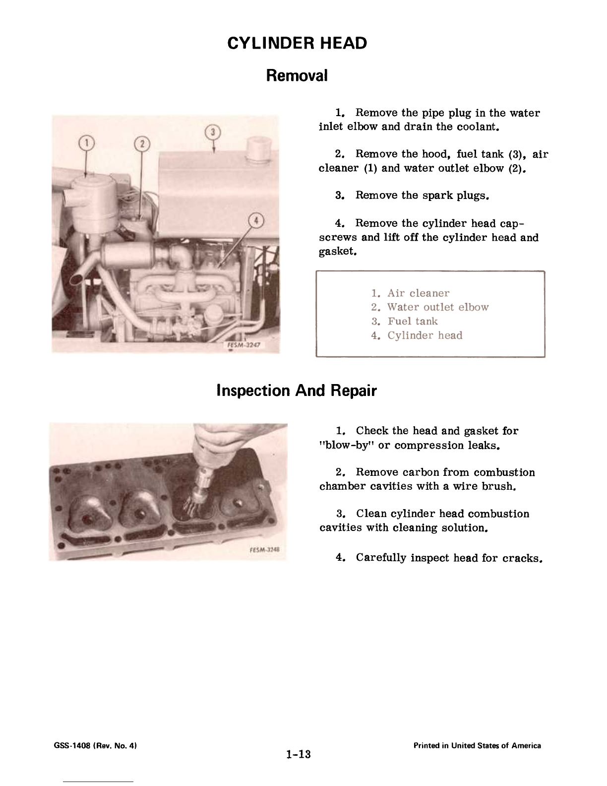
Removal
1. Remove the pipe plug in the water
inlet elbow and drain the coolant.
2. Removethe hood, fuel tank (3), air
cleaner (1)andwater outlet elbow (2).
3.
Removethe sparkplugs.
4. Remove the cylinder head cap-
screws and lift off the cylinder head and
gasket.
Inspection And Repair
1. Checkthe headand gasketfor
"blow-by" or compression leaks.
2. Removecarbon from combustion
chamber cavities with a wire brush.
3. Cleancylinder headcombustion
cavities with cleaning solution.
4.
Carefully inspect headfor cracks.
GSS-1408 (Rev. No. 41 Printed in United States of America
1-13
5. Use a straight edge and inspect for
warped head, particularly in any area
which shows "blow-by."
andcausehot spots. Cleanif necessary
7. Thoroughly clean the gasket surface
to insure proper sealing of the newgasket.
6. Inspect water jacket in head for an
accumulation of rust or lime deposit which
would affect circulation of cooling water
8.
Be sure to use a~ gasket.
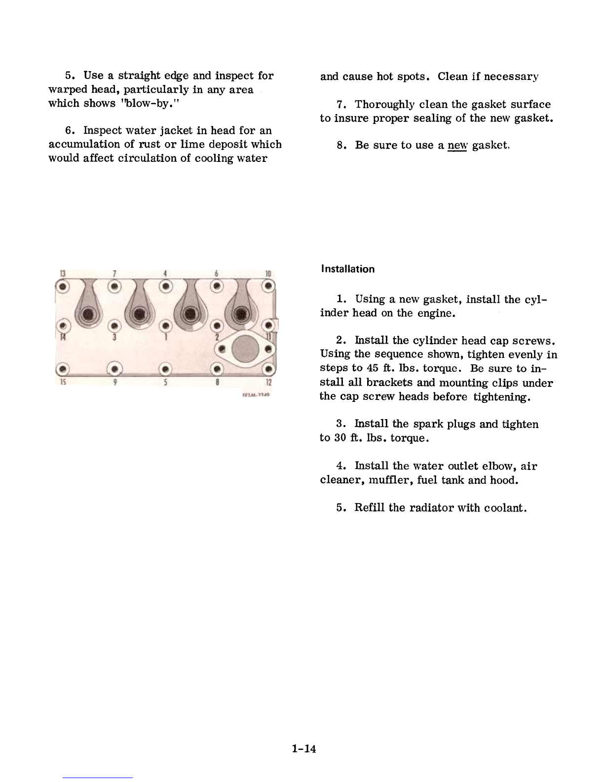
Installation
1. Using a new gasket, install the cyl-
inder head on the engine.
2. Install the cylinder head cap screws.
Using the sequence shoWllt tighten evenly in
steps to 45 ft. lbs. torque. Be sure to in-
stall all brackets and mounting clips under
the cap screw heads before tightening.
3. Install the spark plugs and tighten
to 30ft. lbs. torque.
4. Install the water outlet elbow, air
cleaner, muffler, fuel tank andhood.
5.
Refill the radiator ,vith coolant.
1-14
Valves
valves are adjusted by cranldng the engine
only twice.
Valve lash Adjusting Procedure
Four valves are adjusted when the No.1
piston is at T.D.C. (compression) and the
remaining four are adjusted when the
No.4 piston is at T.D.C. (compression).
Following the simplified procedure in the
chart below, all valves can be adjusted
accurately. Note that the engine does not
need to be cranked four times to position
the piston of each cylinder on T.D.C. All
1. Remove the intake and exhaust
manifold assembly. Remove the valve
tappet cover. With the cover removed,
inspect the entire valve assembly for rust
and dirt. Clean the assembly with clean-
ing solvent. Inspect for looseness in the
valve assembly and for worn or broken
valve springs.
2. Removethe spark plugs from No.1
cylinder (nearestthe radiator) and No.4cylinder.
3. Place a thwnb over the No.1 spark
plug opening and slowly hand crank the
engjne until an oubward pressure can be
felt. Pressure indicates the piston is
moving toward top-dead-center of the
compression stroke.
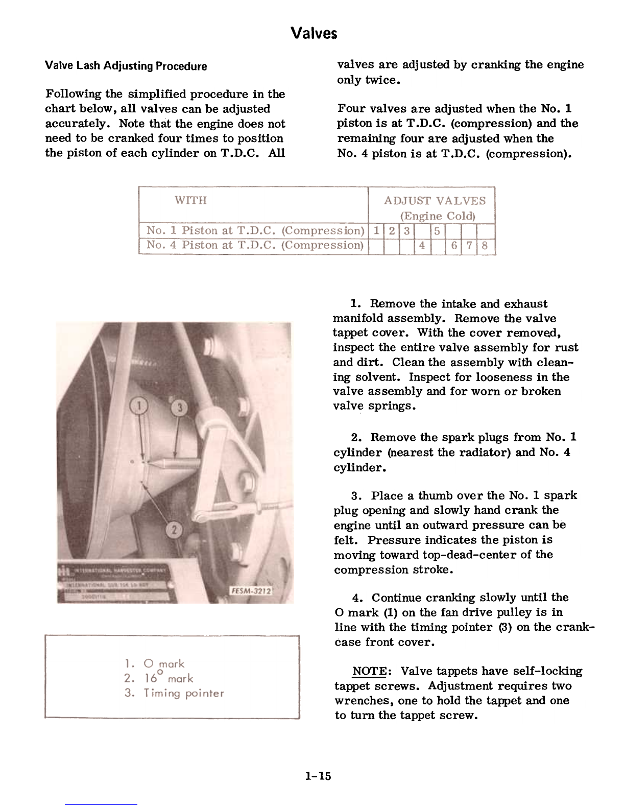
4. Continue cranJdng slowly until the
0 mark (1) on the fan drive pulley is in
line with the timing pointer (J) on the crank-
case front cover.
NOTE: Valve tappets have self-locldng
tappet screws. Adjustment requires two
wrenches, one to hold the tappet and one
to turn the tappet screw.
1-15
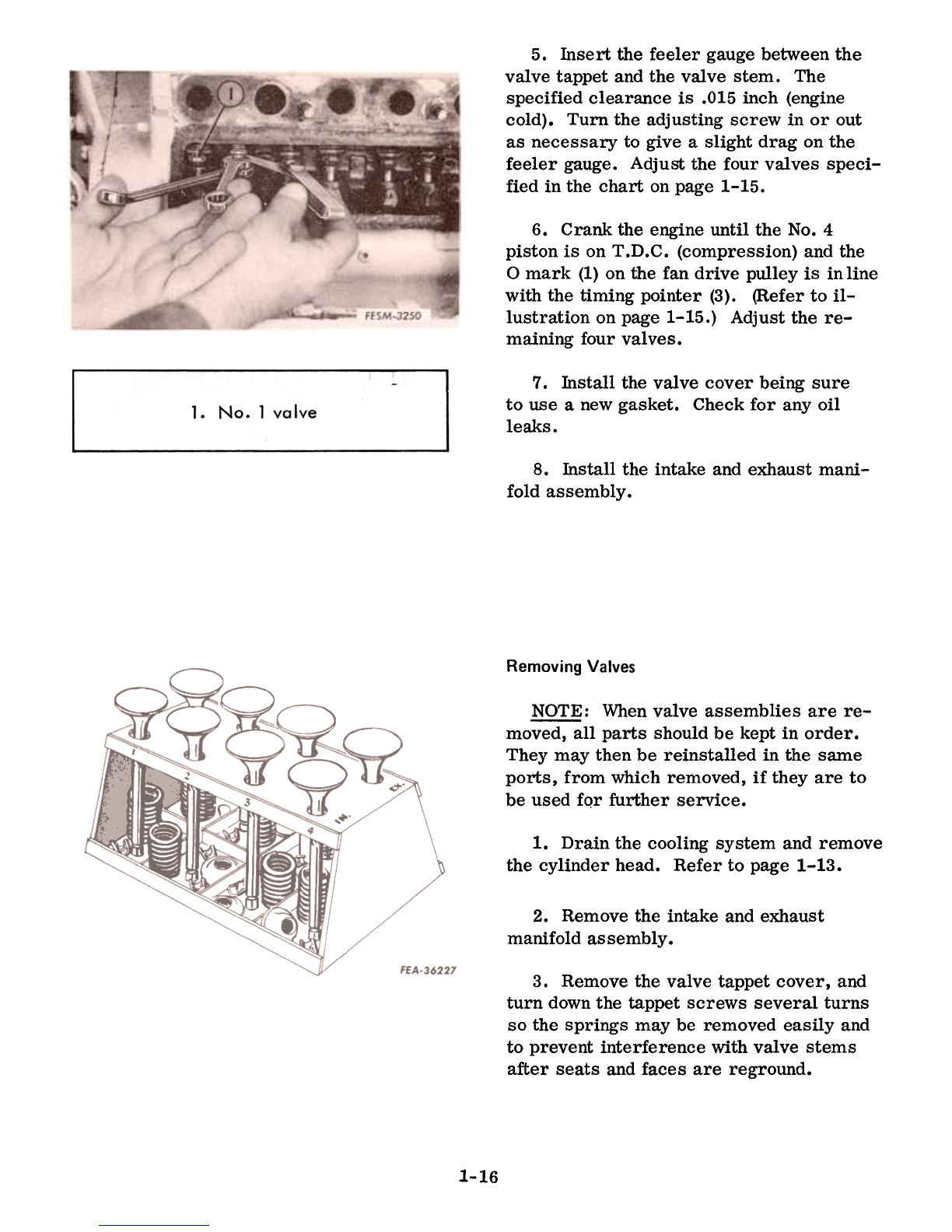
5. Insert the feeler gauge between the
valve tappet and the valve stem. The
specified clearance is .015 inch (engine
cold). Turn the adjusting screw in or out
as necessary to give a slight drag on the
feeler gauge. Adjust the four valves speci-
fied in the chart on page 1-15.
6. Crank the engine until the No.4
piston is on T.D.C. (compression) and the
0 mark (1) on the fan drive pulley is in line
with the timing pointer (3). (Refer to il-
lustration on page 1-15.) Adjust the re-
maining four valves.
7. Install the valve cover being sure
to use a newgasket. Checkfor any oil
leaks.
1. No.1 valve
8. Install the intake and exhaust mani-
fold assembly.
Removing Valves
NOTE: Whenvalve assemblies are re-
moved, all parts should be kept in order.
They may then be reinstalled in the same
ports, from which removed, if they are to
be used fQr further service.
1. Drain the cooling system and remove
the cylinder head. Refer to page 1-13.
2. Removethe intake and exhaust
manifold assembly.
3. Remove the valve tappet cover, and
turn down the tappet screws several turns
so the springs may be removed easily and
to prevent interference with valve stems
after seats and faces are reground.
1-16
Other International Harvester Company Lawn Mower manuals

International Harvester Company
International Harvester Company 105 User manual

International Harvester Company
International Harvester Company 72 User manual

International Harvester Company
International Harvester Company CUB User manual

International Harvester Company
International Harvester Company C-2 User manual

International Harvester Company
International Harvester Company International Cadet 60 User manual

International Harvester Company
International Harvester Company 75 User manual


