Interphace ULTRASCAN PC90 User manual

2
To Our Customer:
Thank you for choosing the Interphase Ultrascan PC90 Forward Scanning Sonar.
Throughout the development of this fine product, we have been primarily concerned with
creating a unit that offers the best possible value for your money. Selection of features,
ease of use, superior performance and outstanding reliability were the benchmarks upon
which all important design decisions were made. We are proud of the Ultrascan PC90
Forward Scanning Sonar and your satisfaction is very important to us. We welcome any
comments or suggestions that you might have about this equipment.
It is very important that you complete and return the WARRANTY REGISTRATION
CARD within 15 days of purchase so that your unit may be protected under the warranty.
Thank You Again,
INTERPHASE TECHNOLOGIES, INC.
©2010 Interphase Technologies, Inc.
Interphase Ultrascan PC90™ is a trademark of Interphase Technologies, Inc.
Other brands or products are the trademarks or registered trademarks of their respective holders and
should be treated as such.
Publication # = Ultrascan PC90 1.0 100414

3
1 Introduction 6
General Information 6
Warranty Information 6
Unpacking and Inspection 7
2 Installing Ultrascan PC90 8
Transducer Installation 8
Thru-Hull Considerations 9
Thru-Hull Transducer Installation 10
Selecting a Location 10
Using a Fairing Block 14
Transom Mount Transducer Installation 13
Selecting a Location 13
Attaching the Bracket 13
Bracket Axel Assembly 15
Beamformer Module Installation 16
Software Installation 17
Connecting to Computer 18
Computer Network Settings 18
Setting Ultrascan PC90 Software’s IP Address 19
3 Quick Start 20
Running Ultrascan PC90 20
Defaults 20
Recordings 20
Beam Width 21
4 Basic Operation 22
Getting Started 22
The Toolbar 22
The Status Bar 23
Operating Modes 23
Playback Mode 23
LIVE Mode 23
Contents

4
Setting System Parameters 24
Beamformer IP Address 24
Transducer Mount Corrections 24
Level Adjustment 24
Align Adjustment 25
Keel Offset 25
Displays 26
Setting Color and Units 26
VERT: Vertical Scan Display 28
HORZ: Horizontal Scan Display 28
DOWN: Downlooker Display 28
VSPLIT: Vertical Split-Screen Display 29
Adjusting the Gain and Range 30
Gain Adjustment 30
Range Adjustment 31
Display Smoothing 32
Depth Window 32
Using the Alarm 33
Adjusting the Depth Tracker 34
Surface Masking 34
Threshold 34
Saving Data with Screen Capture 35
5 Advanced Operation 36
Working with NMEA Navigation 36
Logging Depth 36
Recording Live Data 38
Using Ultrascan PC90 Diagnostics 40
6 Interpreting Displays 40
Principles 40
Interpreting the Vertical Display 40
Forward Imaging Capabilities 40
Transducer Sidelobe Effects 41
Interpreting the Horizontal Display 42
Imaging the Bottom 42
Special Situations 43
Forward Imaging Capabilities 43
7 Reference 44
Maintenance 44
Troubleshooting Guide 45
Interference Problems 46

5
Specifications 47
How To Obtain Service 51
9 Advanced Networking Information 48
Warranty 55

6
General Information
T
hank you for choosing the Interphase Ultrascan
PC90 Dual-Axis Forward Scanning Sonar. The Ul-
trascan PC90 has been designed to work with your
on-board PC or PC Network and will display water
depth, bottom conditions, fish and other submerged
objects and debris, all on your computer’s high
resolution color display. If you already have an
Interphase scanning transducer installed on your
vessel, you can order a Ultrascan PC90 without a
transducer (see page 46).
To insure that you receive the maximum benefits
available from the many features of the Interphase
Ultrascan PC90, this manual includes a detailed guide
to the use and interpretation of the system’s modes
and displays. An instructive demonstration mode has
been designed into the Ultrascan PC90 to familiarize
you with the unit’s features. In addition, the Basic
Operation chapter gives you the necessary
information to get your system up and running as
quickly as possible. Please read the Installation
chapter carefully before attempting to install Ultras-
can PC90 on your vessel.
Warranty Information
Interphase provides a Limited Warranty on the Ul-
trascan PC90 Forward Scanning Sonar. Please read
this warranty (reprinted at the back of this manual)
and closely follow its terms and conditions should
your Ultrascan PC90 require repair. It is highly
recommended that you save all packing materials so
that, in the unlikely event that you must return your
Ultrascan PC90 for repair, it can be fully protected.
Should you experience a problem with your Ultrascan
PC90, first refer to the Troubleshooting section (Page
45) of this manual. Most common problems and their
solutions are described here. If problems persist, call
NAVIGATION WARNING
Nautical navigation is a critical element in
the safety and success of each open-water
boating experience and should only be
performed by experienced navigators.
While the Ultrascan PC90 product is a
useful navigation aid, it should never be
relied upon as the only means of
navigation. It is prudent to use more than
one proven instrument and more than one
accepted method in support of navigation
decisions.
1 Introduction
Award Winning
Technology
For its pioneering work in developing
Phased Array Scanning Sonar,
Interphase Technologies won the
prestigious IMTEC INNOVATION
AWARD.
The Ultrascan PC90 Forward Looking
Scanning Sonar is based
on this same
award-winning technology.

7
Interphase Technical Service at (831) 477-4944, Ext
16. We will be happy to assist you, and if required, we
will give you instructions on how to quickly get your
unit repaired.
The enclosed warranty registration card must be
completed and returned to Interphase within 15 days of
purchase so that your unit may be protected under the
warranty. Failure to return the warranty card may cause
unnecessary delays in processing your unit for warranty
repair.
Unpacking and Inspection
When unpacking your Ultrascan PC90, the following
items should be found in the package. Please notify
your Interphase dealer immediately if any items are
missing.
Standard Equipment
Description Part Number
Beamformer Module D1-0400-001
Ethernet Cable, 10’ length 04-1107-00R
12VDC Power Supply Cable 04-1106-00R
Ultrascan PC90 Software CD 52-1004-001
Operation Manual 25-4018-000
Transducer Options
Description Part Number
Two Transom Transducers
200 kHz Vertical Scan T1-I200-025
200 kHz Horizontal Scan T1-I200-028
Single Thru-Hull Transducer
200 kHz Horizontal/Vertical Scan T1-I200-032
IMPORTANT NOTICE
Please fill out and return the Warranty
Registration Card immediately. This is
our only method of contacting you should
new features and enhancements become
available for your Ultrascan PC90.
During the first year of your warranty,
any software upgrades will be free of
charge, and after the warranty period has
expired, software upgrades will be
available for a nominal charge.
Beamformer Module
Ultrascan PC90
Software CD
6’ DC Power Cable
(2-pin connector)
10’ Ethernet Cable
(RJ-45 Connectors)
8
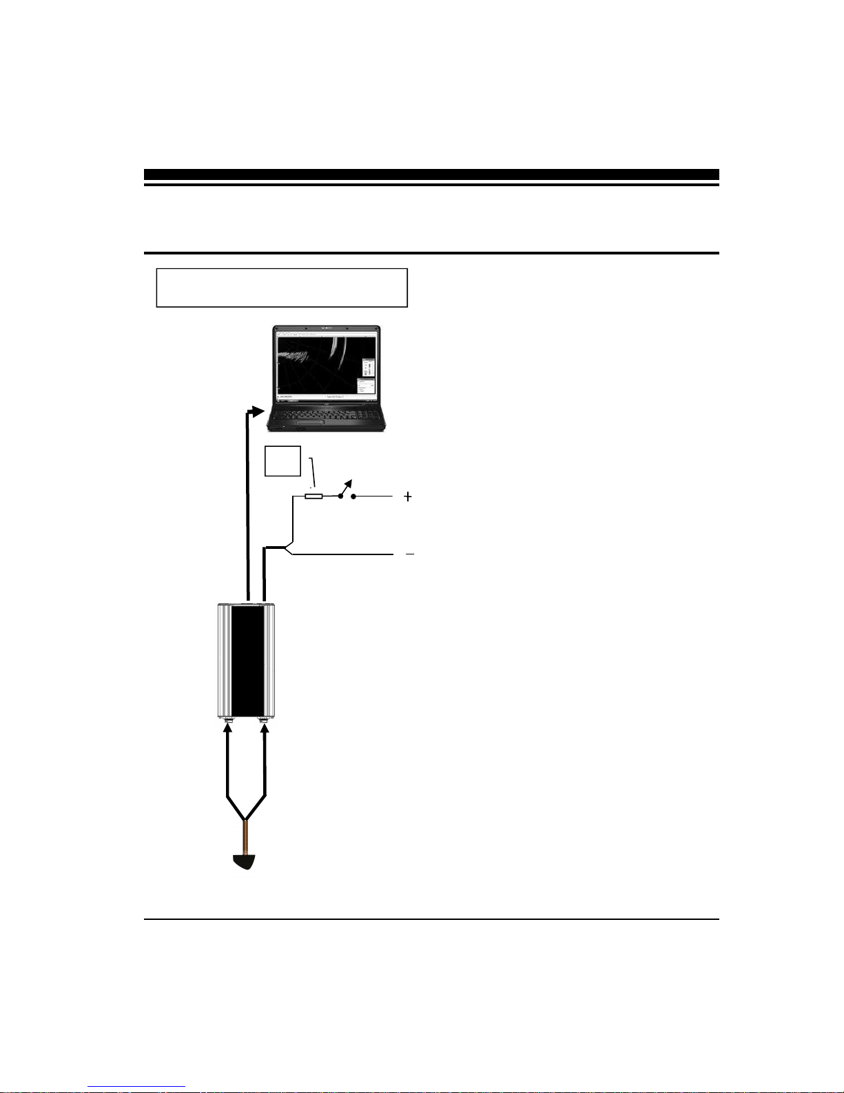
The diagram at left shows a typical installation of the
Ultrascan PC90 using an on-board desktop or laptop
PC.
In this manual, the Ultrascan installation procedures
have been divided into three major sections;
1) Location and Installation of the Transducer(s)
2) Installation of the Beamformer Module
3) Installation of the Ultrascan PC90 Software
Transducer Installation
The Ultrascan PC90 can be ordered with one of two
transducer configurations; two transom mount trans-
ducers or with a single bronze thru-hull transducer or
with no transducer (if you already have an existing
Interphase scanning transducer installed).
The Ultrascan PC90 uses two multi-element phased
transducer arrays. The arrays are “potted” in a
smooth-surfaced tough urethane material that is
acoustically transparent. DO NOT allow any
solvents (i.e. gasoline, acetone) to come in contact
with the transducer(s) as this may dissolve the
plastic housing.
In the single thru-hull configuration all of the trans-
ducer elements are enclosed in a single transducer.
For transom-mount applications two transducers are
required, each containing an 8-element array. One of
the multi-element arrays is positioned to scan
vertically from straight ahead to directly below the
boat, while the other array is positioned to scan
forward horizontally from side to side. When the two
thru-hull configuration is chosen, each transducer
contains an 8-element array. One is positioned for
vertical scanning and the other for horizontal
scanning.
2 Installing Ultrascan
TYPICAL ULTRASCAN PC90
CONFIGURATION
30’ Vertical
Scanning
Transducer
Cable
30’ Horizontal
Transducer
Cable
ETHERNET CABLE
Ultrascan Beam-
former Module
Transducer -
(single thru-hull
INTERPHASE
ULTRASCAN
PC
(or PC Network)
10-36
VDC
Fuse
9
When selecting the transducer type and hull location
for the transducer(s) keep in mind the primary rule for
transducer operation. This is: the transducer can
function as long as it has an unobstructed forward
view and has smooth flowing non-aerated water
surrounding it.
♦
Do not cut or splice your phased array transducer
cable or removing the 9-pin connector as it will
void the transducer warranty.
♦
On both the thru-hull and transom mount trans-
ducers the blunt end is the forward end! See
sketch at right.
♦
♦♦
♦
If you need a longer length cable than comes
with the transducer (30’), then purchase the
optional extension cables, Interphase Part # 04-
0014-008R for 30’ or 04-1014-007R for 10’
lengths. Total transducer cable lengths over 60’
are not recommended as they will decrease the
effective power and depth range.
♦
Choose a location where there is the least
amount of acoustic noise, air bubbles or
turbulence caused by the boat’s movement. The
transducer should not be located nearby or
especially directly behind the propeller.
♦
Choose a location where the transducer can be
mounted so that it will be level to the water’s
surface and will not be tilted to either side.
Otherwise the transducer will not scan from the
surface ahead to directly beneath the boat.
♦
DO NOT install a bronze transducer housing
directly into an aluminum or steel hull because
electrolytic corrosion will occur. Consult your
boat-yard for more information on how to
properly install transducers into these types of
hulls.
♦
DO NOT allow any solvents i.e. gasoline, ace-
tone to come in contact with the transducer head
unit as this may dissolve the urethane material.
In addition, DO NOT force the cable by pulling
on it. This may cause damage to the internal
transducer wiring.
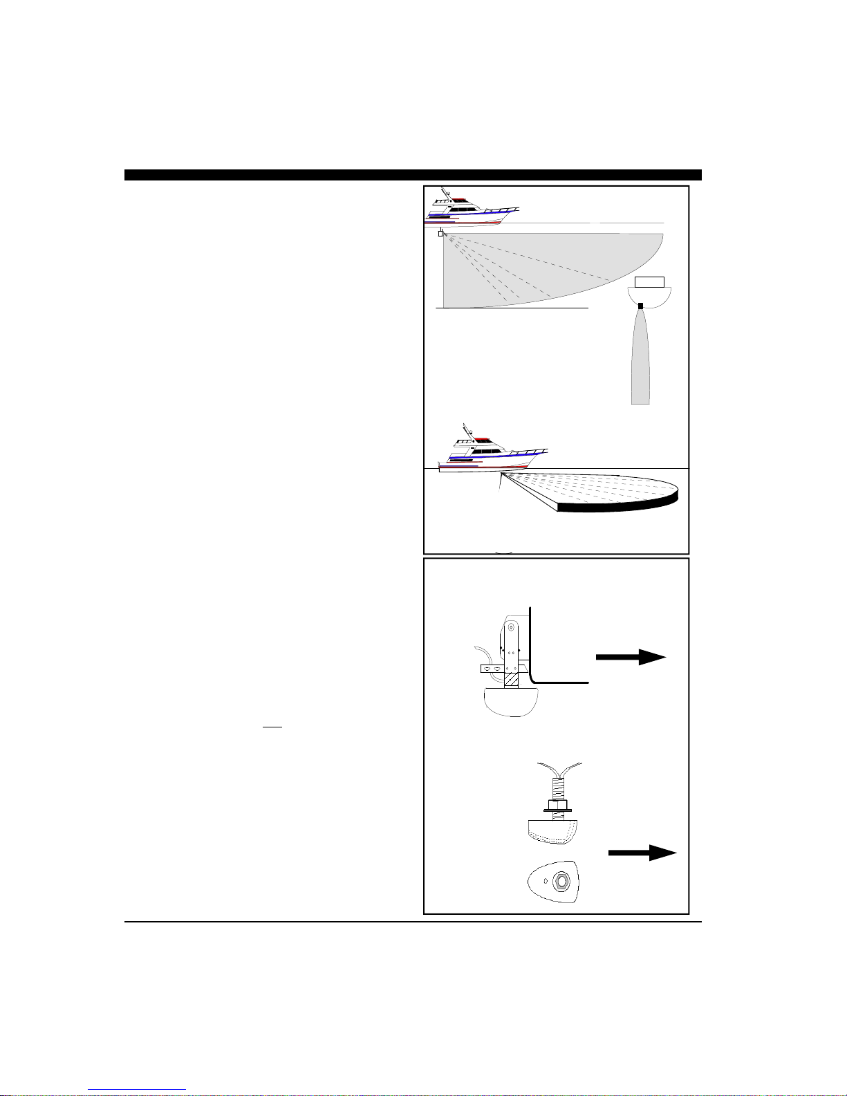
Forward
Forward
Thru-Hull Transducer(s)
Transom Mounted Transducer
Side View
Top View
Scanning Directions.
Vertical Scan mode
shown above and
Horizontal Scan
mode below

10
Thru-Hull Considerations
Thru-hull transducers are for boats that exceed 40MPH
and /or have inboard motors. Transducer placement
depends on boat size, speed, hull configuration and
sonar application. On displacement hulls, the
transducer is generally located between 1/3 and 1/2 aft
of where the bow meets the water line. This is the
farthest forward the transducer should be mounted. It is
important that the transducer be below turbulent aerated
water created by the bow and does not come out of the
water during normal operation or when the boat is
pitching in a seaway.
Make sure the transducer has a clear view ahead and
that there are no forward hull obstructions that can
cause any turbulence in front of the transducer.
Mount so the transducer(s) bronze stem is within ap-
proximately +/- 5 degrees of vertical to insure scanning
in the proper directions. Most vessels will require a
fairing block to compensate for the angle (dead-rise) of
the hull.
Special Thru-Hull Mounting Considerations
On sailboats with a fin keel, the transducer is most
often placed at the leading edge of the keel and
sometimes faired into the keel. As this location may be
where the sling rests when hauling the boat, the
transducer may be placed on either side of the hull with
the foremost face of the transducer even with the
leading edge of the keel. Alternatley, the transducer
may be placed forward of the keel ahead of the lifting
strap location. This should not be ahead of 1/3 aft of
where the bow meets the waterline.
On planing hulls the transducer is typically placed near
the transom. This is to provide smooth flowing water at
the greastest speed. However, most planing hull boats
create transducer aeration when on plane regardless of
transducer location.
It should be noted that thru-hull transducers can effect
boat performance in two important ways. The first
concern is cavitation created by the transducer that
causes reduced engine performance by disrupting water
flow around the propeller. This is smoothed out by the
hull in some boats, but on planing hulls with the
transducer near the transom, the hull is not able to clear
the cavitation. The second concern is uneven drag on
smaller high-speed boats. This may occur when the
Suggested Thru-Hull Transducer Locations
Fin Keel
Planing Hull
Displacement Hull
L = waterline length
~ 1/3 L

11
thru-hull transducer is mounted far off of the
centerline of the boat. At low speeds and on large
boats the effect is negligible. On smaller boats at high
speeds the drag can effect the steering. The effect
increases as the boat’s speed rises. Boats with trim
tabs can usually trim this out, but boats without trim
tabs may feel a pulling sensation toward the
transducer side of the boat.
A less intuative mounting location for the single thru-
hull transducer on a planing hull is on the centerline
just forward of midship. The goal in this mounting is
to place the transducer so that it is out of the water at
planing speed. As most transducers are aerated at
planing speeds, this removes the transducer from the
water flow preventing cavitation and steering
problems. Most applications for forward scanning
sonar occur when the boat is at low non-planing
speeds including fishing and navigating hazardous
waters. Under these lower speed conditions the
transducer is in the water.
Installing the Thru-hull Transducer
♦
Drill a 1/8” pilot hole from inside the hull to
assure access to tighten the housing nut and
clearance for the transducer cables.
♦
Use a 1-1/16” hole saw and drill the hole from
the outside. Sand or clean the area around the
hole, inside and outside to insure that the sealing
compound will adhere properly to the hull.
♦
Remove the bronze hex nut from the housing
and cable.
♦
Uncoil the transducer cable and thread it through
the hole into the inside of the hull.
♦
♦♦
♦
Apply a 1/8” thick layer of sealant on the upper
flat surface of the transducer, bronze alignment
pin and fairing block (if used).
♦
From the outside of the hull, push the housing
into the 1” hole. Twist the housing slightly to
squeeze out excess sealant. Carefully confirm
that the transducer is aligned so that the BLUNT
front end is pointed directly toward the front of
the boat.
♦
Install and tighten the bronze hex nut (allow for
swelling in wooden hulls) and remove excess
sealant from the outside to assure smooth water
flow over the transducer.
ULTRASCAN PC90—90-Degree Vertical and 90-Degree Hori-
zontal Scan
The single ULTRASCAN PC90 thru-hull
transducer (T1-I200-032) contains two phased ar-
rays, one used to scan vertically and the other hori-
zontally. The transducer has two cables, one con-
nected to each array and each is color coded—green
for the vertical array and blue for the horizontal
array.
Because this transducer scans horizontally,
care must be taken to locate it at a position where it
can see 45 degrees either side of the bow (see sketch
at left with side and overhead views). The horizontal
scan plan is angled downward by 10º to minimize
surface clutter.
It can be mounted in front of a fin keel, or just
off to the side of the leading edge of the keel where
unobstructed forward vertical and horizontal views
are available.
On deep full keel vessels (trawlers, etc) it is
usually not possible to find a suitable location for a
single transducer with the horizontal scan. These
vessels should install the ULTRASCAN PC180 sys-
tem with two transducers.
ULTRASCAN PC90
12
DANGER: Wood hulls and wood fairing blocks
will expand after the boat is put back into the water,
so it is important that the transducer be only hand-
tightened until the wood fully expands. Otherwise
the wood fairing block may crack.
DANGER: Be sure to check for leaks when the
boat is placed in the water. Allow at least 24 hours
after installation for any leak to appear.
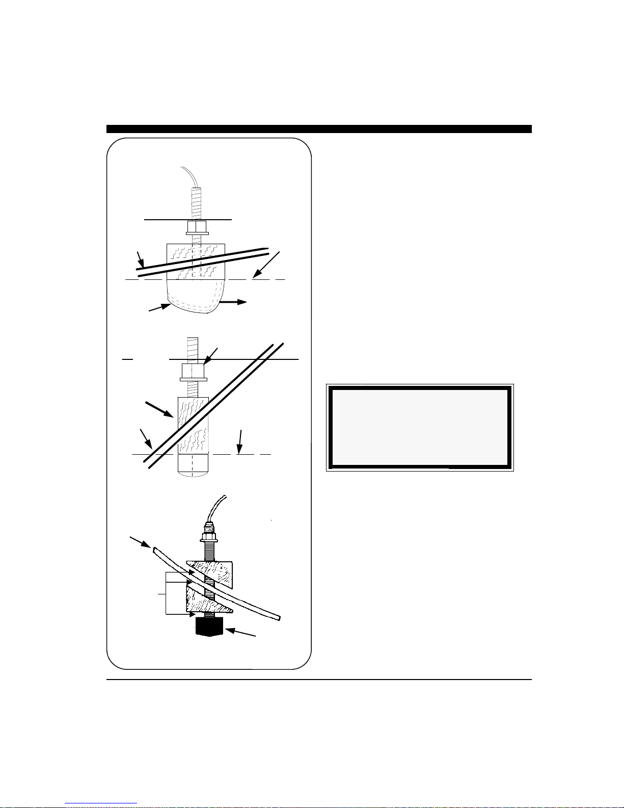
Nearly all vessels have some dead rise angle at the
transducer mounting location. If the thru-hull
transducer were mounted directly to the hull, the
sound beam would be tilted off the vertical at the
same angle as the dead-rise, so most thru-hull
installations will require a fairing block to insure
the transducer is mounted properly.
If you’re installation requires a fairing block, you
may either have one made locally, or purchase a
molded plactic unit from Interphase or your
Interphase distributor. The Interphase part num-
ber for this fairing block is 40-2005-000.
NOTE
The flat top of the transducer must be
parallel to the water line. This will not
necessarily be parallel to the boat’s hull.
Hull
Hull
Waterline
Waterline
Keep parallel
to waterline !
Keep parallel
to waterline !
FORWARD
Transducer
Mount Transducer So Bronze Stem is Vertical
BronzeHex
Nut
Fairing
Block
Transducer
Boat’s
Hull
Underwater Sealant

13
Transom Mount Considerations
Transom mounted transducers are intended for low
speed boats with external props. Boats with inboard
motors and boats that regularly exceed 35MPH can
not use transom mounted transducers. This is because
with inboard motors the prop is located in front of the
transom transducers and create aeration and excess
turbulence.
I/O motors where the prop is aft of the transom do
not create this situation, but be careful that the
driveshaft of the I/O does not block the forward
horizontal scan. Boats that exceed 40MPH run a risk
of having the transom mounted transduers torn free
of the transom. The transom mounted transducers are
not designed to be used at these speeds.
Transom mounted transducers are mounted on kick-
up or break-away brackets. This allows the brackets
to kick up at about speeds above 35-40MPH or if
they strike an object. Once kicked up, the transducers
must be manully reset in order to function.
Transom Transducer Kick-Up
Bracket
The transom transducer is attached to the boat with a
heavy-duty stainless steel kick-up bracket to provide
protection against impact.When the transducer
strikes an object, or the water force exceeds the
resistance of the bracket, the transducer automatically
kicks up and becomes non-operational. The bracket
does not automatically reset at lower speeds. The
transducer must be manually returned to its
operational position.
Special Note: The kick-up feature is designed as a
safety consideration to prevent the transducer from
being removed from the boat due to impact or
excessive speed. The kick-up bracket is not designed
for repeated kick-up or to be pulled up manually
during loading and unloading from boat trailers.
Tests have shown that the bracket can kick-up as
many as 30 times before there is a negative effect on
the bracket. Repeated kick-up will cause the
transducer to kick-up at progressively lower speeds.
Excessive kick-ups can cause the transducer bracket
to fail. Brackets that fail due to repeated kick-up are
not covered under the transducer warranty.
If the transducer must be kicked up for installation,
Suggested materials required for installation:
♦
Variable speed electric drill with a chuck
capacity of 10mm (3/8”) or larger.
♦
Hole saw or spade bit 19 mm (7/8”) for
transom hole to route cable and
connector
♦
Chamfer bit or 6 mm (1/4”) drill bit
♦
Drill bit No. 28 or 4 mm (9/64”)
♦
Drill bit 3 mm (7/64”)
♦
Marine bedding/sealing compound
Note: Will
Not Work at
Speeds Above
35 MPH
Transom Mount Bracket in Released Position
14
boat service or loading, the nylok nut on the end of
the bracket axle can be loosened. Tighten the nut to
50 inch pounds of torque before operating the boat.
through the spacer.
Note: The Forward Horizontal Transducer must be
able to scan beneath the hull. The deadrise angle of
the hull must be less than 10 degrees in order for the
forward horizontal scan to sweep beneath the hull.
Alternately, the transducer can be mounted at or
below the lowest point on the hull.
The transducer can be installed on either side of an
outboard or inboard/outboard engine, or between twin
outboards. For single engine installations, normally
18” to 24” outboard of the propeller center line is
acceptable and the down stroke side of the propeller is
preferred. Choose a location where water flow is
smoothest. For dual engine installation, just off the
center line is usually acceptable.
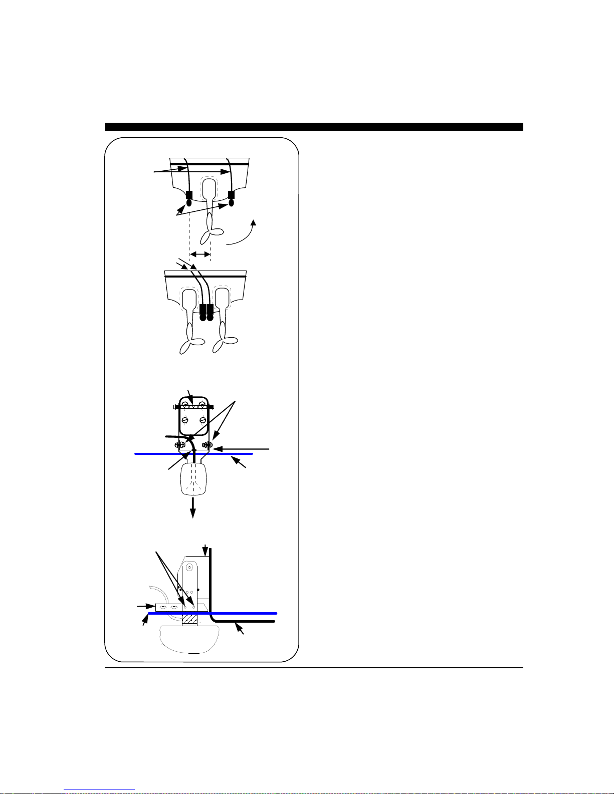
Because the transducer rotates back and upwards
when the bracket releases, it must be mounted in a
location where there is sufficient clearance and
headroom to allow the full release.
Attach the Transducer & Spray Shield to the
Bracket
Locate the Stainless Spray Shield inside the
transducer’s stainless mounting ears. Make sure the
spray shield is orientated as shown in sketch below.
Then, assemble the stainless kick-up bracket to the
transducers using the 4 screws, washers and lock nuts
provided. Place the rubber grommet around the
transducer cable and slide it into the slot in the spray
shield. The bracket arms must be mounted outside the
stainless steel mounting ears of the transducer. Do not
fully tighten the lock nuts at this time. Tighten them
after the transducer is mounted and the spray shield is
positioned.
Position the transducer so that it is perpendicular from
side to side and make sure the wider blunt end is
pointed towards the front of the boat.
Mounting the Transducer to the Boat
After you have selected the optimum mounting
location and have assembled the mounting bracket to
the transducer, mount the bracket onto the hull as
shown on the right.
Make sure to position the transducer so that it is level
in the fore and aft direction and so it will look straight
Waterline
Rear
View
Spray Shield
Transducer must be
mounted vertically
Fasten Spray Shield
with 4 screws & nylok
washers as shown
Bracket
Axle
Rubber
Grommet
Side View
Boat Hull
Mounting
Bracket
Waterline
Fasten Spray Shield
with 4 screws & nylok
washers as shown
Spray
Shield
18 - 24"
Cables
Twin Outboards
Transducers
Cables
Transom Mount Locations

15
down. Check the location of your boat’s waterline
and position the flat top surface of the transducer so
that it is parallel to the waterline as shown below.
Note: If the transducer is not mounted so that its fore
and aft direction is parallel to the surface, then the
forward looking display will be distorted and flat
bottoms will appear to be slanted upwards or
downwards. After mounting the transducer and
actually using the ULTRASCAN on the water, you
may need to readjust the transducer’s mounting for
optimum performance.
Bracket Axle Assembly
On some boats it will be neccessary to remove the
Bracket Axle during installation. See the diagram to
the left and instructions below for details on
assembling the axle.
1. Place one stainless steel washer onto the axle
against the hex end.
2. Place one small stainless steel spacer against
washer.
3. Slide two urethane spacers over the small steel
spacer.
4. With the transducer bracket in place, align the long
stainless steel spacer with the mounting holes of the
mounting bracket and slide the axle in place.through
the spacer.
5. Place one small stainless steel spacer against the
transducer bracket.
6. Slide two urethane spacers over the small steel
spacer.
7. Place one stainless steel washer onto the axel
against the urethane spacer.
8. Place the nylon nut onto the threaded end of the
axel and tighten to 50 inch pounds. If you do not
have a torque wrench, tighten until the nut will not
turn easily. The stainless steel spacers should pre-
vent over-tightening.
Bracket
Axle
Nylon
Nut
1
2
3
5
4
6
7
8
Kick-up Bracket Replacement Parts
If during installation parts are somehow lost are
damaged, they can be replaced as follows:
Part# 17-0088-008 - Spray Shield Kit - Includes:
Spray Shield, four Mounting Bolts and Nuts, Rubber
Grommet and four Large Mounting Screws.
Part# 17-0089-008 - Transom Transducer Hardware
Kit - Includes: Complete Bracket Axle Assembly and
four Large Mounting Screws.
Part# 17-0056-008 - Kick-Up Bracket Assembly -
Includes: Complete Bracket Axle Assembly, four
Large Mounting Screws and the Stainless Steel
Mounting Bracket.

16
Beamformer Installation
The red box that came with your Ultrascan PC90
system is called the Beamformer Module. It houses
the transmitters and receivers that communicate with
the transducers. The Beamformer Module must be
connected by an RJ45 Ethernet cable to your ship-
board PC or PC network, to the transducers and to a
source of 10 to 36 VDC power.
1) Select a location to mount the Beamformer
Module. Keep in mind that the unit must be
protected from from moisture and extreme
temperatures. Also, you will need to route the
Ethernet cable, the power cord and transducer
cables to the location that you choose.
2) Connect the two-pin plug on the end of the
power supply cable to the power supply jack
located at the front of the Beamformer Module.
Connect the red wire to a switch or breaker con-
nected to your ships positive (+) battery sup-
ply.and the black wire to the negative of your
boat’s battery. To prevent accidental damage—
it’s recommended that an inline slow blow 2
Amp fuse also be inserted in the positive lead.
3) Connect one end the Ethernet Cable to the Red
Box and the other to the Ethernet connector on
your PC or to an Ethernet connection on a net-
work switch or router.
4) Connect the two transducer wires to the
matching ports on the back of the Beamformer
Module. They are color coded as follows:
Cable label Port label Color
HORZ HORZ Blue
VERT VERT Green
5) The Ultrascan also includes a ground screw just
to the right of the red data LED. Grounding the
case to a good water ground (engine block,
bonding system, thru-hull, etc) is recommended
as it will help minimize interference from sur-
rounding sources of noise.
Ultrascan Beam-
former Module
Transducer -
(single thru-hull shown)
10-36
VDC
INTERPHASE
ULTRASCAN
2 Amp Slo-Blow Fuse
Switch or
Breaker
Water
Ground
GROUND

17
Software Installation
The Ultrascan PC90 software includes a group of
program files and a demonstration recordings. These
files will all be automatically copied to your computer’s
hard disk during installation.
The total size of the Ultrascan PC90 installation is
about 5 megabytes. We recommend that you make sure
that there is at least 15 megabytes of free space on your
hard drive before you begin the installation. If you plan
to save screen-captured images or record raw sonar
data, you will need additional space. We recommend
beginning with a minimum of 100 megabytes of free
space.
Ultrascan PC90 will run on a computer with Microsoft
Windows XP, Vista or Windows 7. Take the
following steps to install Ultrascan PC90 on your
computer:
1) Exit all programs that are currently running.
2) Insert the Ultrascan PC90 CD Disk into your
computer’s CD drive..
3) Follow the Setup instructions in each dialog box
that is displayed. Click the Next button to accept
the defaults.
The dialog box (shown at right) will prompt you to
accept the default destination folder for the Ultras-
can PC90 files or select a different folder.
The dialog box in the lower right will ask whether
you want to create a desktop icon or a Quick
Launch icon. Most users choose to create an
Ultrascan icon on their desktop.
Ultrascan PC90’s Operating Software is
located on a CD which is included with
your system. The latest software is also
available for download at from the
Interphase website at:
www.interphase-tech.com

18
Connecting to a PC
Set Your Computer’s Ethernet Port’s IP
Address to 192.168.1.3
Using the Ethernet cable provided, connect the Ul-
trascan PC90 to your Computer’s Ethernet port.
The Ethernet port on the Computer should be set to a
static IP address of 192.168.1.3.
To set your computer’s IP address in Windows Vista,
click START —> CONTROL PANEL —> NET-
WORK AND SHARING CENTER. Then click on
MANAGE NETWORK CONNECTONS
Right click on the Network Connection that needs to
be changed (usually the local area connection) and
then select PROPERTIES as shown at top left.
Select INTERNET PROTOCOL VERSION 4(TCP/
IPv4)
And the click on PROPERTIES as shown at mid left.
A pop-up window like that shown at bottom left will
appear. Choose “Use the following IP address”, and
then enter 192.168.1.3 for the IP address, and
255.255.255.0 for the Subnet mask. Click OK to save
your settings and exit the Local Area Connection
Properties.

19
Connect to Ultrascan Beamformer
After setting your PC’s IP address, turn on power to the
Ultrascan PC90. After a few seconds the green power
light will glow.
Wait 30 seconds, then open the Ultrascan PC90 computer
software.
From Ultrascan PC90’s menu, choose SETUP—
>BEAMFORMER, as shown at right. The Beamformer
Settings pop-up window should appear as shown at right.
Enter Beamformer IP Address of 192.168.1.20, and in the
lower section of the window, highlight your computer’s
IP port address which you previously set to 192.168.1.3
Press OK to close the beamformer settings window.
The Orange light on the Ultrascan Beamformer Module
should light when a proper connection between the Beam-
former and PC is made.
The Ultrascan PC90 should now be communicating with
your PC. You should see a red/green blinking indicator
on the bottom toolbar of the Ultrascan PC90. Also, the
word “PLAYBACK” will be replaced with the word
“LIVE”, as in the picture at lower right.
PING LIGHT—BLINKS
RED/GREEN
WHEN
COMMUNICATING
WITH BEAMFORMER
Ultrascan PC90’s Beamformer Module is shipped
with the default IP address of 192.168.1.20.
If needed, the IP address can be changed by using
the Ultrascan Web Server. For more information,
see page 50
20
Running Ultrascan PC90
To start the Ultrascan PC90 system, turn on the
switch or breaker that provides power to the beam-
former module.. Then run Ultrascan PC90 by
clicking on the Ultrascan PC90 icon on your com-
puter’s desktop.
If all components have been installed and all cables
are connected, and the Beamformer Module is on,
Ultrascan PC90 will immediately begin to collect and
display data. Take the following steps to adjust Ul-
trascan PC90 for basic operation:
1) Set defaults as described below. Be sure that
Auto Gain and Auto Range are off.
2) Select a display (see p.26).
3) Select a range setting that is slightly greater than
your current water depth (see p.30).
4) Adjust the gain by first turning it down until little
imagery is visible on the display. Increase the
gain until you begin to see noise, then decrease
the setting by one (see p.30).
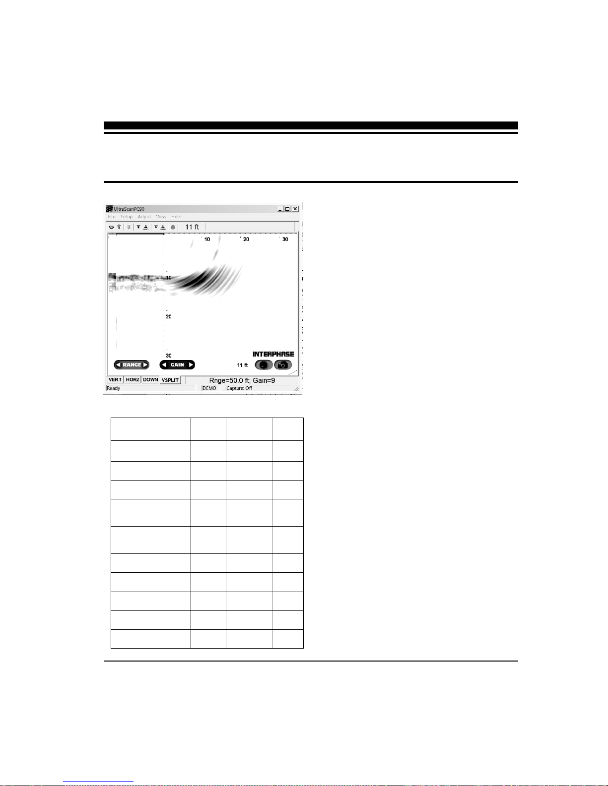
Defaults
The default settings for many of the Ultrascan PC90
features are shown in the table at left. Hard defaults
are always reset when you exit the program. Soft
defaults are recommended settings for general
operation.
If you are running Ultrascan PC90 for the first time, it
will start with the default settings as shown at left.
Change the settings by selecting the appropriate
command from the specified menu.
Demo Recordings
Ultrascan PC90 installation software includes several
actual recordings which can be played back and used
to demo many of the Ultrascan’s features.
3 Quick Start
Parameter Menu Default Type
Auto-Screen Capture File Off Hard
Color Setup Normal Soft
Units Setup Feet Soft
Surface Masking Setup Off Hard
Depth Threshold Setup Normal Hard
Auto Gain Adjust Off Hard
Gain Adjust 10 Soft
Auto Range Adjust Off Hard
Range Adjust 25 Feet Soft
Alarm Adjust Off Hard
Table of contents


