Interpump Group IP User manual

HIGH PRESSURE CLEANER
NETTOYEUR HAUTE PRESSION
HOCHDRUCKREINIGER
HIDROLIMPIADORA ALTA PRESIÓN
LAVADORA A ALTA PRESSÃO
IDROPULITRICE AD ALTA PRESSIONE
INTERPUMP GROUP
• OPERATING INSTRUCTIONS
• MODE D’EMPLOI
• BEDIENUNGSANLEITUNG
• INSTRUCCIONES PARA EL USO
• MANUAL DE INSTRUÇÕES
• LIBRETTO ISTRUZIONI
• DO NOT USE THE MACHINE WITHOUT FIRST READING THE OPERATING INSTRUCTIONS
• N’UTILISER L’APPAREIL QU’APRÈS AVOIR LU LE MANUEL D’INSTRUCTIONS
• GERAT ERST NACH LESEN DER BEDIENUNGSANLEITUNG VERWENDEN
• NO UTILISE EL APARATO SIN LEER ANTES LAS INSTRUCCIONES PARA SU USO
• NÃO USE A MÁQUINA SEM LER A MANUAL DE INSTRUÇÕES
• NON USARE LA MACCHINA SENZA AVERE LETTO LE ISTRUZIONI PER L’USO


3
INDEX
ENGLISH............................................................................................ pag.
FRANÇAIS........................................................................................ pag.
DEUTSCH......................................................................................... pag.
ESPAÑOL.......................................................................................... pag.
PORTUGUÉS................................................................................ pag.
ITALIANO........................................................................................... pag.
6
26
46
66
86
106

4
8
OUTLET
INLET
1
5
7
34
13 910 11
12
• CONTROL DEVICES
Before connecting the machine to the water and electrical supplies, it is necessary to know the function of the controls
on the machine. This must be done in accordance with the descriptions in the Instruction Manual, taking
reference to the relevant instructions and illustrations.
• DISPOSITIFS DE CONTRÔLE
Avant de brancher l’appareil sur les réseaux d’alimentation d’eau et d’électricité, il est nécessaire de bien connaître le
fonctionnement de ses dispositifs de contrôle. Effectuer cette opération en vous référant aux instructions données
dans ce manuel et aux indications et illustrations y relatives.
• BEDIENUNGS - UND KONTROLLVORRICHTUNGEN
Bevor Sie das Gerät mit Wasser - und Stromanschlüssen verbinden ist es notwending, daß Sie die Bedienungs-und
Kontrollvorrichtungen des Gerätes verstehen. Dies muß anhand der Beschreibungen und illustrationen in der
Bedienungsanleitung erfolgen.
• DISPOSITIVOS DE PUESTA EN MARCHA Y CONTROL
Antes de conectar el equipo a las redes de alimentación de agua y electricidad, es necesario conocer sus dispositivos
de puesta en marcha y control. Efectuar estas operaciones siguiendo las indicaciones que figuran en el manual de
istrucciones así como de sus ilustraciones grafícas correspondientes.
• DISPOSITIVO DE COMANDO E CONTROLO
Antes da ligação às redes de alimentação hídrica e eléctrica, é necessário saber qual a função dos dispositivos de
comando e controlo da máquina. Efectuar esta operação conforme descrito no Manual de Instruções.
• DISPOSITIVI DI COMANDO E CONTROLLO
Prima dell’allacciamento alla rete di alimentazione idrica ed elettrica è necessario conoscere la funzione dei dispositivi
di comando e controllo della macchina. Effettuare questa operazione seguendo quanto descritto nel Manuale Istruzioni
facendo riferimento alle indicazioni e illustrazioni relative.
II
IIPP
PP
ss
ssee
eerr
rrii
iiee
eess
ss
2
1
4
6
3
7
5
OUTLET
INLET
8
II
IIPP
PPXX
XX
ss
ssee
eerr
rrii
iiee
eess
ss

5
STANDARD EQUIPMENT
ON/OFF switch
Pressure adjusting knob (IPX)
Pressure gauge
High pressure hose connection (OUTLET)
Inlet hose connection with water filter (INLET)
Outer chemical port (IPX)
Chemical regulator (CHEM)
Built in tank cap
Automatic gun
Lance
Rototek or Multireg 99
High pressure hose
Safety lock
EQUIPEMENT STANDARD
Interrupteur Marche/Arrêt
Bouton de régulation de la pression (IPX)
Manomètre
Raccord de tuyau haute pression (OUTLET)
Raccord d’alimentation eau et filtre (INLET)
Prise du réservoir extérieur détergent (IPX)
Molette de dosage du détergent (CHEM)
Bouchon réservoir incorporé
Pistolet automatique
Lance a raccordement rapide “LANCE”
Rototek ou Multireg 99
Tuyau haute pression
Cran de sûreté
STANDARD AUSRÜSTUNG
EIN/AUS Schalter
Druckregel-Griff (IPX)
Manometer
Hochdruck-Ausgang (OUTLET)
Wasser-Anschluß mit Filter (INLET)
Externe Chemiesaugdose (IPX)
Chemiedosierung (CHEM)
Verschluß des eingebauten Chemietanks
Spritzpistole
Wechsel-Lanze “LANCE”
Rototek oder Multireg 99
Hochdruckschlauch
Sicherheitssperre
EQUIPO STANDARD
Interruptor
Mando de regulación de la presión (IPX)
Mánometro
Salida presión (OUTLET)
Entrada + Filtro agua (INLET)
Entrada aspiración deposito externo (IPX)
Mando de regulación detergente (CHEM)
Tapón deposito interno
Pistola
Lanza
Rototek o Multireg 99
Manguera de alta presión
Seguro
EQUIPAMENTO STANDARD
Interruptor lig/des (ON/OFF)
Manipulo de regulação de pressão (IPX)
Manómetro de pressão
Conector de saida de alta pressão (OUTLET)
Entrada de agua com filtro (INLET)
Entrada de aspiração de detergente (IPX)
Regulador de detergente (CHEM)
Tampa do depósito interno
Pistóla automática
Lança
Bico (ROTOTEK ou MULTIREG 99)
Lanço de tubo de alta pressão
Travão
EQUIPAGGIAMENTO STANDARD
Interruttore
Comando di regolazione della pressione (IPX)
Manometro
Uscita (OUTLET)
Entrata + Filtro acqua
Ingresso aspirazione serbatoio esterno (IPX)
Regolazione detersivo (CHEM)
Tappo del serbatoio interno
Pistola
Lancia
Rototek o Multireg 99
Tubo alta pressione
Sicura

6
TABLE OF CONTENTS
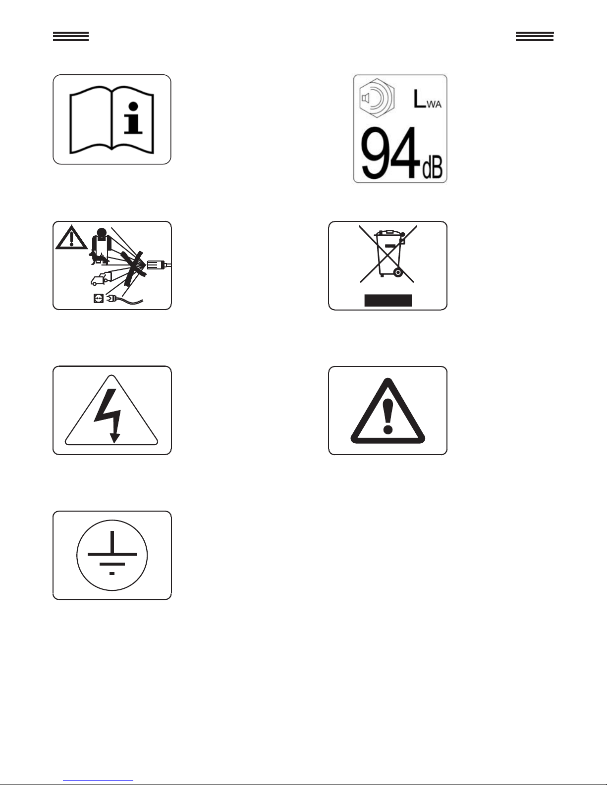
1 - Description of symbols on the high pressure cleaner....................................... 7
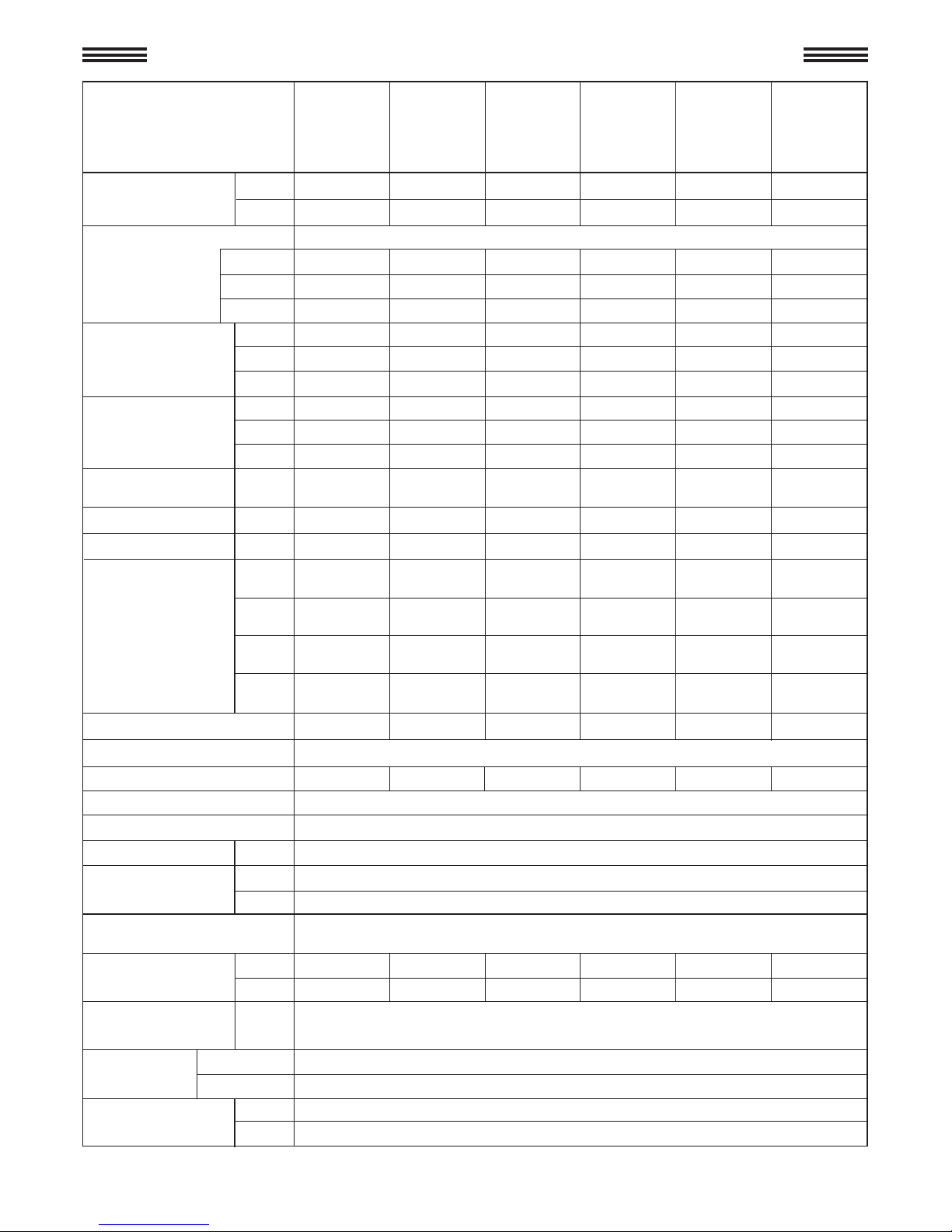
2 - Technical specifications of the IPX - IP series
high pressure cleaner..................................................................................8-9-10
3 - Product use....................................................................................................... 11
3.1 • Designated use................................................................................... 11
4 - Preliminary operations...................................................................................... 11
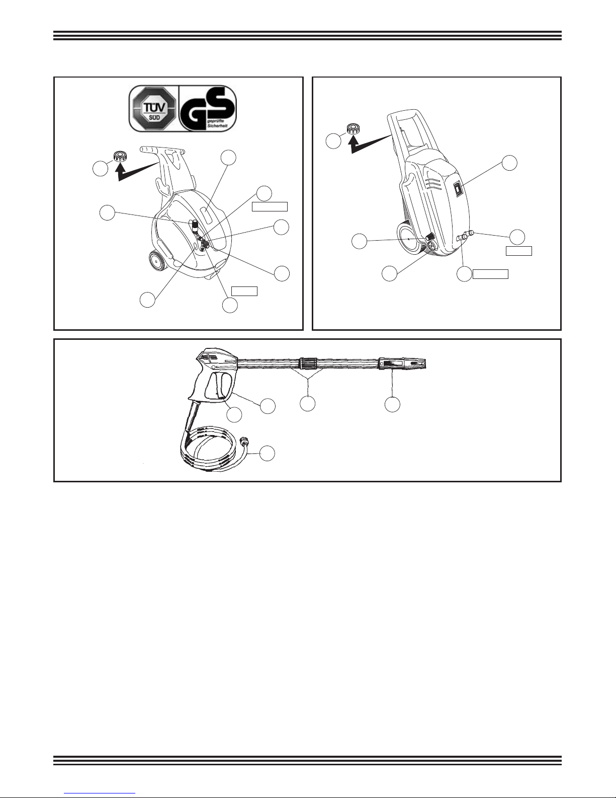
4.1 • Unpacking........................................................................................... 11
4.2 • Identification label............................................................................... 12
5 - Installation......................................................................................................... 12
5.1 • Connection high pressure outlet......................................................... 13
5.2 • Connection to water supply................................................................ 13
5.3 • Connection to electric system............................................................ 14
5.3.1 • Cut-out switch (Only the United States).......................................... 15
5.4 • Use of extention cord......................................................................... 15
5.5 • Start-up............................................................................................... 16
6 - General warnings.............................................................................................. 17
7 - Chemical product use...................................................................................... 20
7.1 • Suction from internal tank (IP) ........................................................... 20
7.2 • Suction from internal tank (IPX) ......................................................... 20
7.3 • Suction from external tank (IPX) ........................................................ 20
8 - Use of "ROTOTEK" or "MULTIREG 99"........................................................... 21
9 - Precautions againt freezing, and instructions for storage................................... 21
10 - Maintenance...................................................................................................... 22
10.1 • Oil change.....................................................................................22-23
10.2 • Inlet filter............................................................................................ 23
10.3 • Replacement of high pressure nozzle ............................................. 23
11 - Machine scrapping............................................................................................ 24
12 - Trouble shooting............................................................................................... 25
ENGLISH

7
1 - DESCRIPTION OF SYMBOLS ON THE HIGH PRESSURE CLEANER
DDoo nnoott ddiirreecctt tthhee jjeett
aaggaaiinnsstt ppeerrssoonnss oorr
aanniimmaallssppoowweerr oouutt--
lleettss oorr tthhee mmaacchhiinnee
iittsseellff..
WWaarrnniinngg!! RRiissk
k ooff
eelleeccttrrooccuuttiioonn
GGrroouunnddiinngg
SSppeecciiaall wwaassttee.. DDoo
nnoott ddiissppoossee ooff tthhiiss
pprroodduucctt iinn nnoorrmmaall
hhoouusseehhoolldd ggaarrbbaag
gee
WWaarrnniinngg ssiiggnn
RReeaadd tthhee iinnssttrruuccttiioonn
mmaannuuaall bbeeffoorree uussee..GGaarraanntteedd ssoouunndd
ppoowweerr lleevveell..

8
2 - IPX SERIES HIGH PRESSURE CLEANERS TECHNICAL SPECIFICATIONS
MODEL
Voltage
Amps
V
A
Capacitor
Motor protection
Isolating class insulation
Motor protection grade
°C
m/sec2Fixed nozzle A(8) than 2,5 - Rotating nozzle A(8) 7 (uncertainly 1)
Max. water inlet
temp °F
m
Max suction depth ft
High pressure hose Steel reinforced rubber - Internal diameter 1/4”
Working pressure max 210 bar - 21 MPa - 3045 P.S.I.
Mass
Dimensions mm
inches
Noise level*
Lance vibration*
V
A
P.S.I.
Overpressure
peak limit
Recoil thrust of jet N
Absorbed motor power kW
Cycle Hz
l/min.
Flow rate G.P.M.
USA
E.W. bar / MPa / P.S.I.: specific jet pressure in bar / MPa / P.S.I.
Equivalent
washing impact
with rotating
nozzle jet
E.W. MPa
E.W. P.S.I.
Working pressure
MPa
E.W. bar
bar
P.S.I.
MPa
bar
MPa 1 - bar 10 - P.S.I. 145
Max inlet pressure
*(Reference Standard EN60335-2-79).
dry
(max.)
8 m
26 ft
IPX
15.150.2
15.150.3
15.150.4
15.150.5
TRIPLE PHASE
IPX
10.130.2
10.130.4
SINGLE PHASE
IPX
12.100.2
12.100.4
SINGLE PHASE
IPX
12.140.2
12.140.3
TRIPLE PHASE
IPX
14.120.2
14.120.3
TRIPLE PHASE
IPX
13.180.2
13.180.3
13.180.4
13.180.5
TRIPLE PHASE
V
A
V
A
2.5
9,5
3.1
12
3.1
12
3.7
14
3.4
13
3.9
15
23 17 24,5 21 31 26
230 170 245 210 310 260
3200 2465 3450 2950 4400 3770
130 100 140 120 180 150
13 10 14 12 18 15
1885 1450 2030 1740 2610 2175
160 130 170 150 210 180
16 13 17 15 21 18
2320 1885 2465 2175 2950 2610
< 29 < 32 < 40 < 41 < 47 < 49
3,2 3,2 3,8 3,8 55
50 50 50 50 50 50
230-1
14,7
230-1~
14,7
230-3~
12,5
230-3~
12,5
230-3~
15,8
230-3~
15,8
240-1~
13,6
240-1~
13,6
400-3~
7,2
400-3~
7,2
400-3~
9,2
400-3~
9,2
240-3~
14,5
240-3~
14,5
415-3~
8,5
415-3~
8,5
2x40µF 2x40µF ––––
Thermal
FFFFFF
IPX5
Lp dB(A) 80 (uncertainly 1,5) - Lw dB(A) 94
60
140
3333
9,9 9,9 9,9 9,9
11
3,3 3,3
Kg 43,5 - Ibs 96
Kg 67,5 - Ibs 148,8
460x530x830 (h)
18,1x20,9x32,7 (h)
––––
––––

9
MODEL
Voltage
Amps
V
A
Capacitor
Motor protection
Isolating class insulation
Motor protection grade
°C
m/sec2Fixed nozzle A(8) than 2,5 - Rotating nozzle A(8) 7 (uncertainly 1)
Max. water inlet
temp °F
m
Max suction depth ft
High pressure hose Steel reinforced rubber - Internal diameter 1/4”
Working pressure max 210 bar - 21 MPa - 3045 P.S.I.
Mass
Dimensions mm
inches
Noise level*
Lance vibration*
V
A
P.S.I.
Overpressure
peak limit
Recoil thrust of jet N
Absorbed motor power kW
Cycle Hz
l/min.
Flow rate G.P.M.
USA
E.W. bar / MPa / P.S.I.: specific jet pressure in bar / MPa / P.S.I.
Equivalent
washing impact
with rotating
nozzle jet
E.W. MPa
E.W. P.S.I.
Working pressure
MPa
E.W. bar
bar
P.S.I.
MPa
bar
MPa 1 - bar 10 - P.S.I. 145
Max inlet pressure
*(Reference Standard EN60335-2-79).
dry
(max.)
8 m
26 ft
IPX
961.6
961.8
TRIPLE PHASE
IPX
17.130.2
17.130.3
17.130.4
17.130.5
TRIPLE PHASE
IPX
951.6
SINGLE PHASE
IPX
954.6
SINGLE PHASE
IPX
956.6
TRIPLE PHASE
IPX
957.6
SINGLE PHASE
V
A
V
A
4.5
17
3
11,5
3.6
13,6
3.4
13
4.2
15,9
3.9
15
23 17 16 25 14,5 26
230 170 160 250 145 260
3200 2465 2320 3550 2100 3770
130 103 90 145 76 150
13 10,3 9 14,5 7,6 15
1885 1500 1300 2100 1100 2175
160 133 120 175 106 180
16 13,3 12 17,5 10,6 18
2320 1929 1740 2538 1537 2610
< 51 < 31 < 35 < 41 < 37 < 49
5,0 3,2 3,2 4,6 3,2 5,0
50 60 60 60 60 60
230-3~
15,8 220-1~
15,5
220-1~
15,5
220-3~
16,5
220-1~
15,5
220-3~
15,8
400-3~
9,2 –
2x40µF
2x40µF 2x40µF –
Thermal
FBBFBF
IPX5
Lp dB(A) 80 (uncertainly 1,5) - Lw dB(A) 94
60
140
1113
3,3 3,3 3,3 9,9
11
3,3 3,3
Kg 43,5 - Ibs 96
Kg 67,5 - Ibs 148,8
460x530x830 (h)
18,1x20,9x32,7 (h)
240-3~
14,5
415-3~
8,5
–
–
–
––
––
–
–
–
–
–
380-3~
9,2
–
––
2 - IPX SERIES HIGH PRESSURE CLEANERS TECHNICAL SPECIFICATIONS

10
MODEL
Voltage
Amps V
A
Capacitor
Motor protection
Isolating class insulation
Motor protection grade
°C
m/sec2Fixed nozzle A(8) than 2,5 - Rotating nozzle A(8) than 2,5
Max. water inlet
temp °F
m
Max suction depth ft
High pressure hose Steel reinforced rubber - Internal diameter 1/4”
Working pressure max. 150/210 bar - 15/21 MPa - 2175/3045 P.S.I.
Mass
Dimensions mm
inches
Noise level*
Lance vibration*
P.S.I.
Overpressure
peak limit
Recoil thrust of jet N
Absorbed motor power kW
Cycle Hz
l/min.
Flow rate G.P.M.
USA
E.W. bar / MPa / P.S.I.: specific jet pressure in bar / MPa / P.S.I.
Equivalent
washing impact
with rotating
nozzle jet
E.W. MPa
E.W. P.S.I.
Working pressure
MPa
E.W. bar
bar
P.S.I.
MPa
bar
MPa 1 - bar 10 - P.S.I. 145
Max inlet pressure
*(Reference Standard EN60335-2-79).
** With nozzle (code 140)
dry
(max.)
8 m
26 ft
IP130.2
SINGLE PHASE
IP140.2
SINGLE PHASE
IP150.2
IP150.4
SINGLE PHASE
IP170.3
IP170.5
TRIPLE PHASE
2.1
8
2.1
8
2.5
9,5
3.4
13
23 24,5 26 29
230 245 260 290
3200 3450 3770 4200
130 140 150 170
13 14 15 17
1885 2030 2175 2465
160 170 180 200
16 17 18 20
2320 2465 2610 2900
< 23 < 24 < 30 < 44
2,2 2,4 3,2 4,3
50 50 50 50
230-1~
9,6
230-1~
11,1
230-1~
14,7
400-3~
8
30µF 40µF –
Amperometrico termico
F
IPX5
Lp dB(A) 78 (uncertainly 1,5) - Lw dB(A) 94
60
140
0,5
1,65
Kg 32,5 - Ibs 71,6
Kg 37 - Ibs 81,5
550x400x760 (h)
21,7x15,7x29,9 (h)
23
230
3200
130
13
1885
160
16
2320
< 27
3,0
50
240**-1~
13
2,2
50
240-1~
9,6
2,4
50
240-1~
11,1
4,3
50
415-3~
8
50µF
2 - IP SERIES HIGH PRESSURE CLEANERS TECHNICAL SPECIFICATIONS

11
WE CONGRATULATE YOU on your choice that shows your level of technical knowledge and
love of beautiful objects.
In fact, you have purchased a highly technological machine produced by the world's
largest manufacturer of high pressure cleaner pumps.
This machine is so useful and versatile that you will use it for many years.
THIS BOOKLET IS AN INTEGRAL PART OF YOUR MACHINE AND SHOULD BE
CAREFULLY READ BEFORE PROCEEDING WITH INSTALLATION, START-UP AND
USE.
This booklet contains important safety information and instructions for use and maintenance
of the high pressure cleaners series IP and IPX and should be kept in a safe place.
3. PRODUCT USE
The machine is exclusively designed for washing, by way of a pressurized water jet, objects,
things or any surface suitable for cleaning by a pressurized water jet with the possibility of
adding liquid detergent.
ATTENTION: this appliance was designed for use of detergents recommended by the manu-
facturer. The use of other chemical products may jeopardize the safety of the appliance itself.
The liquid detergent additives must be chosen in consideration of the chemical compatibility
with the components of the pump and of the surface to be cleaned.
IMPORTANT: use only detergents that are biodegradable, and in any case complying with the
regulations applicable in the country where they are used.
3.1 DESIGNATED USE
4. PRELIMINARY OPERATIONS
4.1 UNPACKING
Unpack and make sure that the machine is complete and undamaged.
If the machine appears damaged in any way, do not use the machine and consult our dealer.
For shipping reasons some parts may be included separately. In this case assemble parts as
indicated in this booklet.
Keep all packaging materials (bags, boxes, tape) out of reach of children.
THE DESTINATION OF USE OF THIS MACHINE MUST BE STRICTLY ADHERED TO. ANY
OTHER USE MUST BE CONSIDERED AS INCORRECT.
THE MANUFACTURER CANNOT BE HELD RESPONSIBLE FOR DAMAGES CAUSED BY
INCORRECT USE OF THE MACHINE.
THE MACHINE MUST NOT BE TAMPERED WITH FOR ANY REASON. IN CASES OF
TAMPERING THE MANUFACTURER DECLINES ANY RESPONSABILITY ON THE FUNC-
TIONING AND SAFETY OF THE MACHINE.
IT IS FORBIDDEN TO STORE OR USE THE UNIT IN ENVIRONMENTS WITH POTEN-
TIALLY EXPLOSIVE ATMOSPHERE.

12
Before using this machine make sure that it has an ID label. If it is without, do not use the
machine and consult your dealer immediately.
IPX-IP series high pressure cleaners
The Identification Label with the technical specifications is fixed to the machine.
4.2 - ID LABEL
5 - INSTALLATION
OIL
2
1
3
IPX Series
Remove the housing Substitute the red shipping cap (Position 1) with the
yellow and black cap with oil dipstick (Position 2).
Check that the level of the oil is at half way of the sight
glass (Figure 3).

13
5.1 HIGH PRESSURE CONNECTION
1 - Connect one end of the high pressure hose to the end of the automatic gun (A) and the other
end to the OUTLET connection on the machine. Tighten firmly (B).
2 - Complete the assembly by coupling the extension to the gun/lance and tighten firmly (C).
5.2 - CONNECTION TO THE WATER SUPPLY
1- The maximum temperature of the inlet water must not exceed 60°C (140°F).
2- Connect the water supply to the INLET (D) port by means of a reinforced hose (min.15 bar /
1,5 MPa / 200 PSI) with the internal diameter not less than 13mm (1/2”)
3- Since the water flow decreases according to the length of the hose, make sure that the quan-
tity of water supplied to the machine is not less than the quantities indicated in the chart below.
4- The pressure of the inlet water must not exceed 10 bar / 1 MPa / 145 PSI.
ATTENTION: The water supply which enters into the washer is not drinkable.
IMPORTANT
The water supplied to the machine must be clean. Running the unit without water, or with water
which is dirty, contains grit or corrosive liquids, causes serious damage to the machine.
C
A
OUTLET
B
INLET Dø 13 mm.
C
A
OUTLET
B
INLET Dø 13 mm.
IP SERIES FLOW RATE OF
WATER SUPPLY
MODEL L/min. G.P.M. USA
IP130
IP140
IP150
IP170
11
11
13
17
2,9
2,9
3,4
4,5
MODEL L/min. G.P.M. USA
IPX SERIES FLOW RATE OF
WATER SUPPLY
IPX 10-130
IPX12-100
IPX 12-140
IPX 951
IPX 14-120
IPX13-180
IPX 954- 956
IPX 15-150
IPX17-130
IPX 957- 961
15
17
20
4
4.5
5.3
If the user wishes to power the washer by means of free suction, simply emerge the end of the
supply tube in the water to be suctioned. The maximum suction depth considered as the dis-
tance in height between the water surface and the pump varies between 0,5 m. and 3 m. (see
technical specifications table).

14
5.3 - CONNECTION TO ELECTRICAL SYSTEM
1 - Check that the voltage of the electrical system (mains) is the same as indicated on the ID
label of the machine.
2 - Check that the plug complies with local safety regulations, and that it is provided with
ground connection (earth).
3 - Ensure that the outlet is protected by a "cut-out" (differential magnetic-thermal switch with
sensitivity of less than 30mA per 30ms) or that a device is present which can test the earthing
circuit.
4 - Do not connect other appliances contemporaneously to the same power outlet.
5 - Insert the plug only after checking that the machine switch is in the OFF position.
The IPX series and the model IP170 of the IP serie are supplied without electric plug.
The assembly of the electrical plug must be done in conformity with IEC rule n. 60364-1 and
must be effected by qualified personnel, respecting following prescriptions:
1- Use a plug which complies with the local safety regulations and which must necessarily be
grounded.
2- Make sure that the cord/plug connection is perfectly sealed and water-tight.
3- Use plugs that conform to the indications on the ID Tag.
4- Unroll the cord completely to avoid overheating.
5- Do not crush on the power cord.
6- Do not use the high pressure cleaner if the electric cable is damaged.
7- If the power cord is damaged, its replacement can be effected only by the technical service
personnel or by a qualified technician.
In case of direct connection without plug, the connection to the electric network must be in
compliance with the standard IEC 60364-1 and must be made by a qualified installer. If a plug
connector is used as a sectioning device, this must be in an easily accessible position.
In the threephase models the three power leads of the power cord can be connected to any of
the three phases from the power network. The fourth, green-yellow lead must be connected to
the ground pin.
The standard plug supplied with the 50 Hz version of models IP130, IP140, IP150 from the IP
series is: type SCHUKO 250V - 16A, rule EEC-VII DIN49441 - 2-AR2
The washer must only be connected to a power mains with a maximum network impedance of
Zmax=0.3 Ω.
WARNING: IN CASE OF POWER FAILURE DURING USE OF THIS MACHINE, TURN
THE MACHINE POWER SWITCH TO THE OFF POSITION FOR SAFETY REASONS.

15
5.4 - USE OF CORDS
If an extension cord is used, make sure that plug and receptacle are of a water-tight type. In
any case they must be raised from the ground in order to avoid possible contact with water.
Do not use damaged extension cords. Cables should not be located near sources of heat or
sharp edges. Always disconnect the plug from the socket before removing the extension cord
from the product. Do not pull the cable to pull the plug out of the outlet. Do not touch the plug
or connections with wet hands.
WARNING
USE OF INADEQUATE
EXTENSION CORDS
MAY CAUSE SAFETY
HAZARDS
SELECTION TABLE
Voltage
230÷240
230÷240
400÷415
Extension
cord length
Cord section
mm2
Up to 20 m
From 20 to 50 m
Up to 50 m
2,5
4
2,5
5.3.1 - CUT-OUT SWITCH (Only the United States)
This UL version high-pressure washer is equipped with a cut-out switch contained in the power
cable plug.
Said equipment provides extra protection against the risk of electric shock.
When replacing the plug or cable, use the same components including the cut-out device.

16
5.5 - START-UP
- Before starting up and using the machine, make sure that it is positioned on the ground or
leaning against a stable support and that the resting surface is level or with a minimum slope.
- It is ESSENTIAL to ensure that the suction filter is clean before use. (see maintenance chap-
ter – 10.2 suction).
1- Open water supply
2- Push ON button
3 - Open the gun with nozzle end up and keep in open position to allow air to escape from the
hose.
4 - Regulate water pressure by rotating the regulator knob (only on IPX series)
ATTENTION: in the cleaners of the IPX series, high pressure with “TOTAL STOP”
device, the motor stops approximately 20 seconds after the gun is closed.
You are ready to work!!!
5 - At the end of working session turn the machine switch to the OFF position.
6 - Open the gun to release remaining pressure from the hose.
ON
CLICK
IPX SERIES
OFF
CLICK

17
6 - GENERAL WARNINGS
High pressure cleaners can be used neither
by children nor by non authorized persons.
Children must be supervised to prevent them
from playing with the machine.
Keep this machine out of reach of children
at all times.
This equipment was not designed to be used
by persons with reduced physical, sensorial or
mental capabilities, or with limited experience
or knowledge, unless a person responsible for
their safety provides them with supervision or
the instructions for the use of the equipment.
Only operate the machine in safety condi-
tions, avoiding any potentially dangerous
situation for the user and others. The machine
operator should:
• Avoid to operate the machine on unbalanced
surfaces;
• Remember that the high pressure water jet
causes a recoil effect on the pistol. The recoil
values are indicated in the technical specifica-
tions table;
• Use protective clothing.
• Wear protective goggles and rubber slip-
proof boots
• Avoid dispersing substances that are pollut-
ing, toxic or harmful in any way.
ATTENTION: Risk of explosion. Do not spray
flammable liquids.
The high pressure water jet may be dangerous if used incorrectly. Never direct the jet at per-
sons and/or animals, electrical appliances or the machine itself. Do not use the machine when
persons and/or animal are within the range of its high pressure jet.
Do not direct the jet against yourself or other persons to clean clothes or shoes.
NO
NO
NO

18
This machine has been built in conformity
with current safety regulations. Use of electric
appliances requires the observations of a few
simple rules:
Do not touch electric parts when the machine
is on.
Inspection, maintenance and repairs should be
carried out by qualified personnel. In any case
unplug the machine before performing any of
the above operations.
Do not pull the cord to disconnect the power
supply and do not pull on the hose to move the
machine.
ATTENTION: high pressure flexible hoses,
high pressure connectors, safety devices,
electrical connections and spray guns are
important for the safety of the device.
Do not start the unit if the power cord is
damaged. Apply to qualified personnel for its
replacement. Replacement cords should have
the same technical specifications as the origi-
nal cord. Do not carry out repairs on the elec-
trical cord and avoid cord damage.
Do not start the unit if the high pressure hose, connectors and the gun are damaged. By
replacement make sure that the new components have at least the same rating as the original
components.The technical specifications of the hose should be printed on the hose itself (max
pressure, production date, manufacturer).
NO
NO
NO

19
The unit is equipped with a current-thermal over-
load protector which switches and electrically
disconnects the motor in case of overheating.
If this should happen, please refer to the "Trouble
Shooting" section in this manual.
Avoid covering the machine during use and
use the machine in a well ventilated area.
When the machine is off insert the safety
device on the gun to avoid accidental opening.
To ensure the security of the machine, use only original spare parts and accessories supplied
by the manufacturer.
THE MANUFACTURER CANNOT BE HELD RESPONSABLE FOR ANY DAM-
AGE CAUSED BY DISRESPECTING THE DESIGNATED USES OF THIS
MACHINE, IT'S INSTRUCTIONS AND WARNINGS INDICATED IN THIS
BOOKLET.
Do not leave the machine running for more
than 5 minutes with the pistol closed. After
this time period the water temperature within
the machine increase and may cause damage
to the machine.
NO
NO

20
7 - HOW TO USE CHEMICAL PRODUCTS
The IP and IPX series high pressure cleaners have been constructed to permit the suction and
mixing of detergents and other liquids from the internal tank.
In the event of direct contact with detergent additives, follow instructions provided by the man-
ufacturer and/or product retailer and rinse the affected body part with clean water.
7.1 - SUCTION FROM INTERNAL TANK OF IP SERIES
Fill as indicated in Fig. 1. Select low pressure on Rototek or Multireg 99 (Fig. 2) Regulate the
quantity of detergent using the +/- knob (Fig. 3).
7.2 - SUCTION FROM INTERNAL TANK OF IPX SERIES
Fill as indicated in Fig. 1. Select low pressure on Rototek or Multireg 99 (Fig. 2). Ensure that
the cap is securely closed and in position (Fig.3). Regulate the quantity of detergent using the
+/- knob (Fig. 3).
7.3 - SUCTION FROM EXTERNAL TANK IPX SERIES
Remove suction hose from chemical port (Fig. 1). Insert kit "A" in the chemical port (CHEM)
(Fig. 2) and the end with filter into the external tank (B).
HL
HL
IPX
IP
1
2
3
123
This manual suits for next models
1
Table of contents
Languages:
Other Interpump Group Pressure Washer manuals

Interpump Group
Interpump Group TX 10.130 User manual

Interpump Group
Interpump Group TX 10.130.2 User manual

Interpump Group
Interpump Group TX 300 10-130.2 User manual

Interpump Group
Interpump Group TSX User manual

Interpump Group
Interpump Group Boxjet Turbo 15 User manual

Interpump Group
Interpump Group T Series User manual
Popular Pressure Washer manuals by other brands

Briggs & Stratton
Briggs & Stratton Speed Clean Operator's manual

HSS Hire
HSS Hire 59134 Operating & safety guide

Hotsy
Hotsy 797SS Operating instructions and parts manual

Husky
Husky POWERWASHER 1750 US installation guide

Kärcher
Kärcher HD 7/20 G Classic manual

Parkside
Parkside PHD 100 C2 translation of original operation manual