IR Ingersoll Rand 6LH1A1 User manual

Refer All Communications to the Nearest
Ingersoll–Rand Office or Distributor.
Ingersoll–Rand Company 2000
Printed in U.S.A.
03534666Form P6784
Edition 8
October, 2000
OPERATION AND MAINTENANCE MANUAL
FOR SERIES 6L ANGLE DRILLS
Series 6L Angle Drills are designed for drilling operations in the aerospace, automotive,
appliance, electronic, machining and furniture industries.
Ingersoll–Rand is not responsible for customer modification of tools for applications on
which Ingersoll–Rand was not consulted.
IMPORTANT SAFETY INFORMATION ENCLOSED.
READ THIS MANUAL BEFORE OPERATING TOOL.
IT IS THE RESPONSIBILITY OF THE EMPLOYER TO PLACE THE INFORMATION
IN THIS MANUAL INTO THE HANDS OF THE OPERATOR.
FAILURE TO OBSERVE THE FOLLOWING WARNINGS COULD RESULT IN INJURY.
PLACING TOOL IN SERVICE
•Always operate, inspect and maintain this tool in
accordance with American National Standards
Institute Safety Code for Portable Air Tools
(ANSI B186.1).
•For safety, top performance, and maximum
durability of parts, operate this tool at 90 psig
(6.2 bar/620 kPa) maximum air pressure at the inlet
with 3/8” (10 mm) inside diameter air supply hose.
•Always turn off the air supply and disconnect the
air supply hose before installing, removing or
adjusting any accessory on this tool, or before
performing any maintenance on this tool.
•Do not use damaged, frayed or deteriorated air
hoses and fittings.
•Be sure all hoses and fittings are the correct size
and are tightly secured. See Dwg. TPD905–1 for a
typical piping arrangement.
•Always use clean, dry air at 90 psig
(6.2 bar/620 kPa) maximum air pressure. Dust,
corrosive fumes and/or excessive moisture can ruin
the motor of an air tool.
•Do not lubricate tools with flammable or volatile
liquids such as kerosene, diesel or jet fuel.
•Do not remove any labels. Replace any damaged
label.
USING THE TOOL
•Always wear eye protection when operating or
performing maintenance on this tool.
•Always wear hearing protection when operating
this tool.
•Keep hands, loose clothing and long hair away from
rotating end of tool.
•Anticipate and be alert for sudden changes in
motion during start up and operation of any power
tool.
•Keep body stance balanced and firm. Do not
overreach when operating this tool. High reaction
torques can occur at or below the recommended air
pressure.
•Tool accessories may continue to rotate briefly after
throttle is released.
•Air powered tools can vibrate in use. Vibration,
repetitive motions or uncomfortable positions may
be harmful to your hands and arms. Stop using any
tool if discomfort, tingling feeling or pain occurs.
Seek medical advice before resuming use.
•Use accessories recommended by Ingersoll–Rand.
•Whenever the Angle Head is installed or
repositioned, the Throttle Lever must be positioned
so that reaction torque will not tend to retain the
throttle in the “ON” position.
•This tool is not designed for working in explosive
atmospheres.
•This tool is not insulated against electric shock.
The use of other than genuine Ingersoll–Rand replacement parts may result in safety hazards, decreased tool
performance, and increased maintenance, and may invalidate all warranties.
Repairs should be made only by authorized trained personnel. Consult your nearest Ingersoll–Rand Authorized
Servicenter.
F
E
P
TPD1401

2
WARNING LABEL IDENTIFICATION
FAILURE TO OBSERVE THE FOLLOWING WARNINGS COULD RESULT IN INJURY.
Always wear eye protection
when operating or perform-
ing maintenance on this
tool.
WARNING WARNING
Always wear hearing
protection when operating
this tool.
Always turn off the air sup-
ply and disconnect the air
supply hose before install-
ing, removing or adjusting
any accessory on this tool,
or before performing any
maintenance on this tool.
WARNING
Air powered tools can vibrate
in use. Vibration, repetitive
motions or uncomfortable po-
sitions may be harmful to your
hands and arms. Stop using
any tool if discomfort, tingling
feeling or pain occurs. Seek
medical advice before resum-
ing use.
WARNING Do not carry the tool by
the hose.
WARNING WARNING
Do not use damaged, frayed
or deteriorated air hoses
and fittings.
WARNING
Keep body stance balanced
and firm. Do not overreach
when operating this tool.
WARNING
Operate at 90 psig (6.2 bar/
620 kPa) Maximum air pressure.
90 psig
(6.2bar/620kPa)
PLACING TOOL IN SERVICE
LUBRICATION
Ingersoll–Rand No. 10 Ingersoll–Rand No. 67
Always use an air line lubricator with this tool.
We recommend the following Filter–Lubricator–Regulator
Unit:
USA –C18–03–FKG0–28
Motor
Before starting the Tool and after each eight hours of
operation, unless the air line lubricator is used, detach the
air hose and inject a few drops of oil into the air inlet.
Gearing
For models with H, J, JJ, K, or L gearing, after each
50,000 cycles or 160 hours of operation, whichever comes
first, inject 6 – 8 cc of Ingersoll–Rand No. 67 Grease into
the Grease Fitting.
For models with M, P, or R gearing, after each 50,000
cycles or 160 hours of operation, whichever comes first,
inject 10 – 12 cc of Ingersoll–Rand No. 67 Grease into the
Grease Fitting.
Angle Head
For models with the 7L1A1 Angle Attachment, after
each eight hours of operation, inject 0.5 – 1 cc of
Ingersoll–Rand No. 67 Grease into the Grease Fitting.
For models with the 7L2A4 or 7L3A4 Angle
Attachment after each forty hours of operation, inject
0.5 – 1 cc of Ingersoll–Rand No. 67 Grease into the Grease
Fitting.
MAIN LINES 3 TIMES
AIR TOOL INLET SIZE
TO
AIR
SYSTEM
TO
AIR
TOOL
LUBRICATOR
REGULATOR FILTER
BRANCH LINE 2 TIMES
AIR TOOL INLET SIZE
DRAIN REGULARLY COMPRESSOR
(Dwg. TPD905–1)

3
PLACING TOOL IN SERVICE
HOW TO ORDER AN ANGLE DRILL
LEVER THROTTLE ANGLE HANDLE LEVER THROTTLE ANGLE DRILL
Female Female
Free Speed Threaded Free Speed Threaded
Model rpm Stall Torque Spindle Model rpm Stall Torque Spindle
6LH1A1 6 000 23 1/4”–28 6LK2A41 2 000 65 1/4
6LJ1A1 5 100 27 1/4”–28 6LL2A42 1 400 95 1/4
6LJJ1A1 3 950 35 1/4”–28 6LP3A43 600 190 1/4
6LK1A1 3 100 45 1/4”–28 6LR3A44 400 320 1/4
6LL1A1 2 150 64 1/4”–28

Adressez toutes vos communications au Bureau
Ingersoll–Rand ou distributeur le plus proche.
Ingersoll–Rand Company 2000
Impriméaux É.U.
MANUEL D’EXPLOITATION ET D’ENTRETIEN
DES PERCEUSES D’ANGLE DE LA SÉRIE 6L
NOTE
Les perceuses d’angle de la Série 6L sont destinées aux opérations de perçage dans les industries
de l’aérospatiale, de l’automobile, des appareils ménagers, de l’électronique, de l’usinage et des
meubles.
Ingersoll–Rand ne peut être tenu responsable de la modification des outils par le client pour les
adapter àdes applications qui n’ont pas étéapprouvées par Ingersoll–Rand.
ATTENTION
D’IMPORTANTES INFORMATIONS DE SÉCURITÉSONT JOINTES.
LIRE CE MANUEL AVANT D’UTILISER L’OUTIL.
L’EMPLOYEUR EST TENU DE COMMUNIQUER LES INFORMATIONS
DE CE MANUEL AUX EMPLOYÉS UTILISANT CET OUTIL.
LE NON RESPECT DES AVERTISSEMENTS SUIVANTS PEUT CAUSER DES BLESSURES.
MISE EN SERVICE DE L’OUTIL
•Toujours exploiter, inspecter et entretenir cet outil
conformément au Code de sécuritédes outils
pneumatiques portatifs de l’American National
Standards Institute (ANSI B186.1).
•Pour la sécurité, les performances optimales et la
durabilitémaximale des pièces, cet outil doit être
connectéàune alimentation d’air compriméde 6,2 bar
(620 kPa) maximum àl’entrée, avec un flexible de
10 mm de diamètre intérieur.
•Couper toujours l’alimentation d’air compriméet
débrancher le flexible d’alimentation avant d’installer,
déposer ou ajuster tout accessoire sur cet outil, ou
d’entreprendre une opération d’entretien quelconque
sur l’outil.
•Ne pas utiliser des flexibles ou des raccords
endommagés, effilochés ou détériorés.
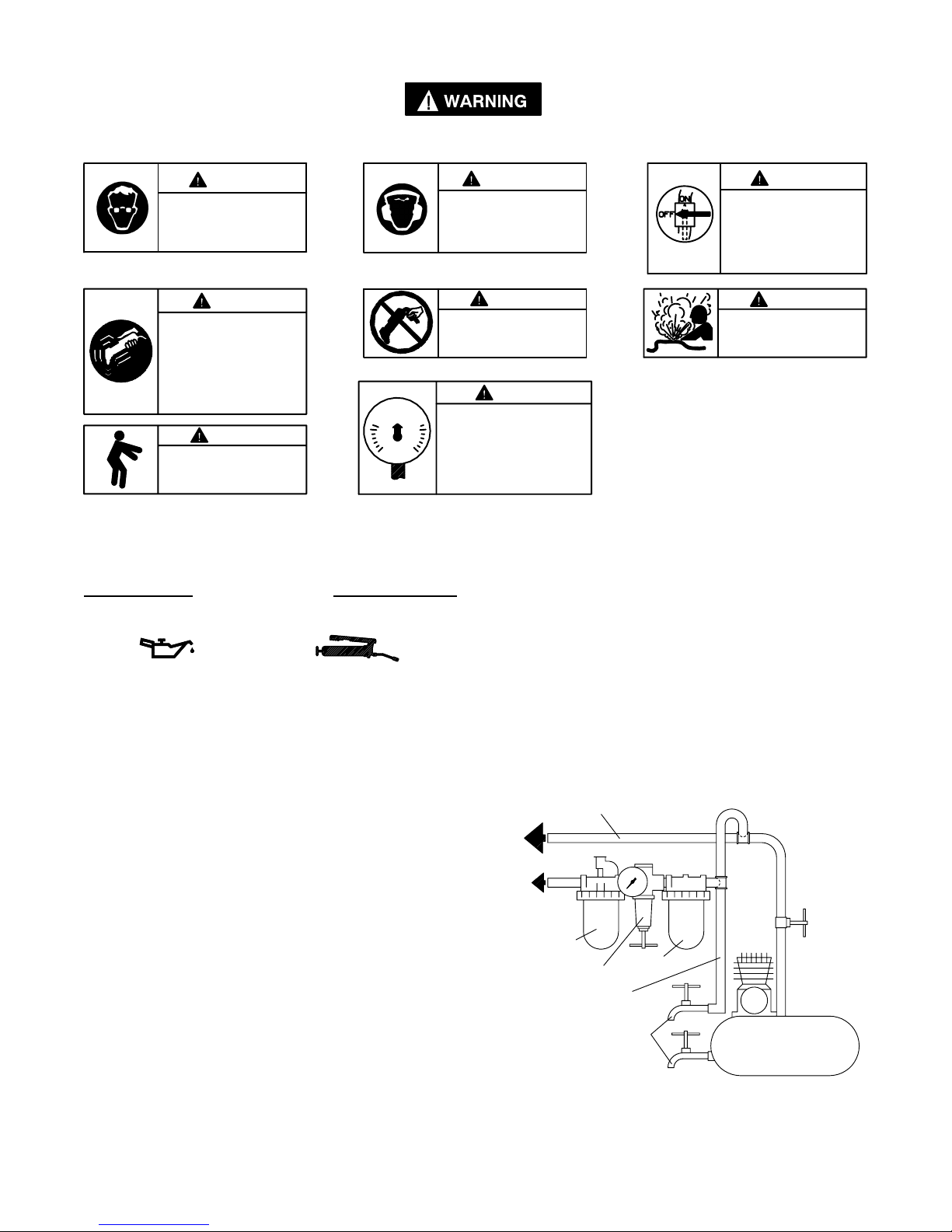
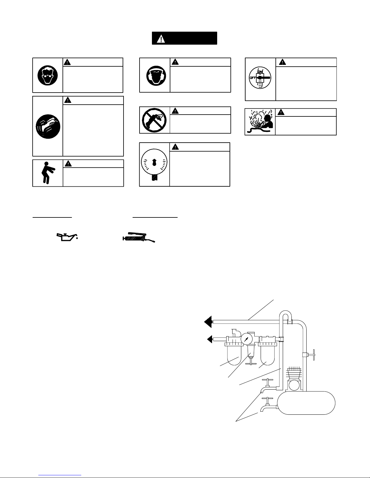
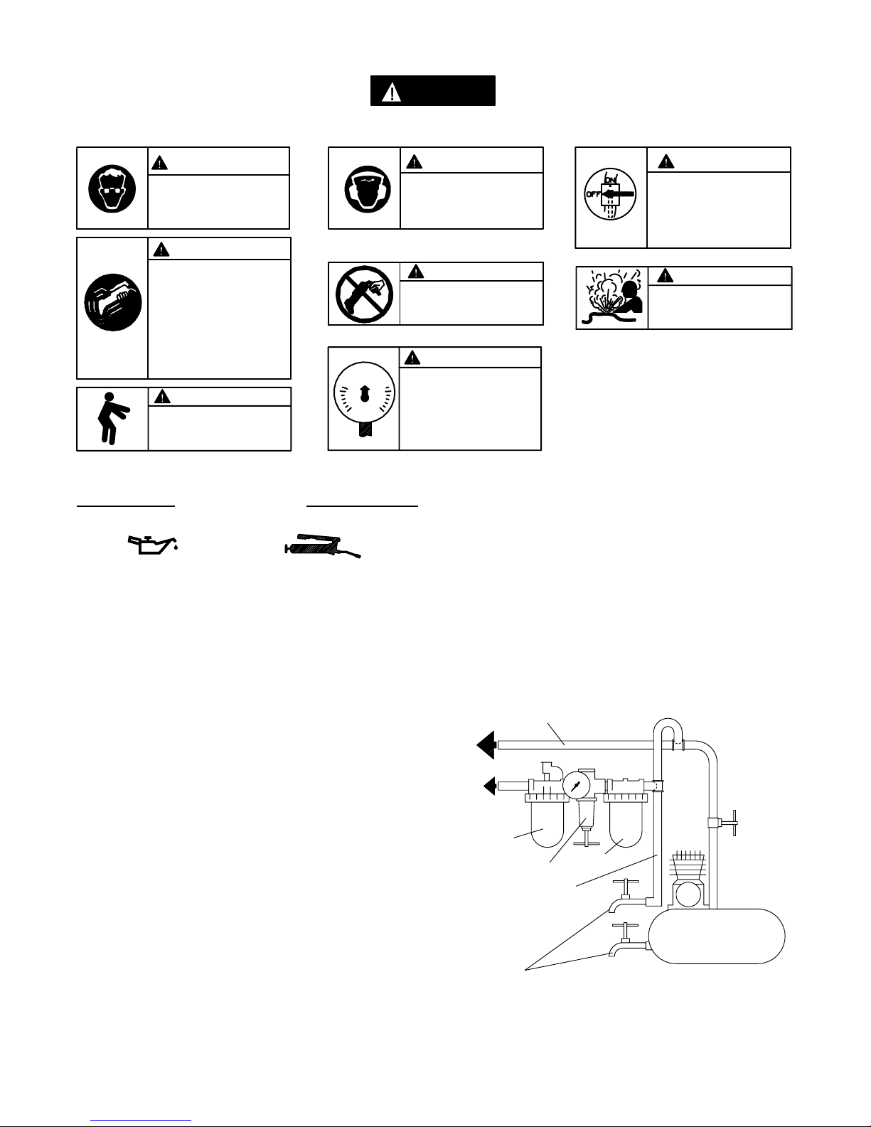
•S’assurer que tous les flexibles et les raccords sont
correctement dimensionnés et bien serrés. Voir Plan
TPD905–1 pour un exemple type d’agencement des
tuyauteries.
•Utiliser toujours de l’air sec et propre àune pression
maximum de 6,2 bar (620 kPa). La poussière, les
fumées corrosives et/ou une humiditéexcessive peuvent
endommager le moteur d’un outil pneumatique.
•Ne jamais lubrifier les outils avec des liquides
inflammables ou volatiles tels que le kérosène, le gasoil
ou le carburant d’aviation.
•Ne retirer aucune étiquette. Remplacer toute étiquette
endommagée.
UTILISATION DE L’OUTIL
•Porter toujours des lunettes de protection pendant
l’utilisation et l’entretien de cet outil.
•Porter toujours une protection acoustique pendant
l’utilisation de cet outil.
•Tenir les mains, les vêtements flous et les cheveux
longs, éloignés de l’extrémitérotative de l’outil.
•Prévoir, et ne pas oublier, que tout outil motoriséest
susceptible d’à–coups brusques lors de sa mise en
marche et pendant son utilisation.
•Garder une position équilibrée et ferme. Ne pas se
pencher trop en avant pendant l’utilisation de cet outil.
Des couples de réaction élevés peuvent se produire à,
ou en dessous, de la pression d’air recommandée.
•La rotation des accessoires de l’outil peut continuer
pendant un certain temps après le relâchement de la
gâchette.
•Les outils pneumatiques peuvent vibrer pendant
l’exploitation. Les vibrations, les mouvements répétitifs
et les positions inconfortables peuvent causer des
douleurs dans les mains et les bras. N’utiliser plus
d’outils en cas d’inconfort, de picotements ou de
douleurs. Consulter un médecin avant de
recommencer àutiliser l’outil.
•Utiliser les accessoires recommandés par
Ingersoll-Rand.
•A chaque fois que le renvoi d’angle est installéou
repositionné, le levier de commande doit être
positionnéde manière àce que le couple de réaction
n’ait pas tendance àmaintenir le levier de commande
en position “MARCHE”.
•Cet outil n’est pas conçu pour fonctionner dans des
atmosphères explosives.
•Cet outil n’est pas isolécontre les chocs électriques.
NOTE
L’utilisation de rechanges autres que les pièces d’origine Ingersoll–Rand peut causer des risques d’insécurité, réduire les
performances de l’outil et augmenter l’entretien, et peut annuler toutes les garanties.
Les réparations ne doivent être effectuées que par des réparateurs qualifiés autorisés. Consultez votre Centre de Service
Ingersoll–Rand le plus proche.
F

5
SIGNIFICATION DES ÉTIQUETTES D’AVERTISSEMENT
ATTENTION
LE NON RESPECT DES AVERTISSEMENTS SUIVANTS PEUT CAUSER DES BLESSURES.
Porter toujours des lunettes
de protection pendant
l’utilisation et l’entretien de
cet outil.
ATTENTION ATTENTION
Porter toujours une
protection acoustique
pendant l’utilisation de cet
outil.
Les outils pneumatiques
peuvent vibrer pendant
l’exploitation. Les vibrations,
les mouvements répétitifs et les
positions inconfortables
peuvent causer des douleurs
dans les mains et les bras.
N’utiliser plus d’outils en cas
d’inconfort, de picotements ou
de douleurs. Consulter un
médecin avant de recommencer
àutiliser l’outil.
ATTENTION
Ne pas transporter l’outil
par son flexible.
ATTENTION
ATTENTION
Garder une position équilibrée et
ferme. Ne pas se pencher trop
en avant pendant
l’utilisation de cet outil.
ATTENTION
Utiliser de l’air comprimé
àune pression maximum
de 6,2 bar (620 kPa).
90 psig
(6.2bar/620kPa)
Couper toujours l’alimentation
d’air compriméet débrancher le
flexible d’alimentation avant
d’installer, déposer ou ajuster
tout accessoire sur cet outil, ou
d’entreprendre une opération
d’entretien quelconque sur l’ou-
til.
ATTENTION
ATTENTION
Ne pas utiliser des flexibles ou
des raccords endommagés,
effilochés ou détériorés.
MISE EN SERVICE DE L’OUTIL
LUBRIFICATION
Ingersoll–Rand No. 10 Ingersoll–Rand No. 67
Utiliser toujours un lubrificateur avec cet outil.
Nous recommandons l’emploi du filtre–régulateur–
lubrificateur suivant :
É.U. –C18–03–FKG0–28
Moteur
Avant de mettre l’outil en marche et tous les huit heures
de fonctionnement, si un lubrificateur de ligne n’est pas
utilisé, débrancher le flexible d’alimentation et injecter
plusieurs gouttes d’huile dans le raccord d’admission.
Pignonnerie
Pour les modèles équipés de la pignonnerie H, J, JJ, K
ou L, tous les 50 000 cycles ou 160 heures de
fonctionnement, selon le cas, injecter 6 –8 cm3de graisse
Ingersoll–Rand No. 67 dans le raccord de graissage
Pour les modèles équipés de la pignonnerie M, P ou R,
tous les 50 000 cycles ou 160 heures de fonctionnement,
selon le cas, injecter 10–12 cm3de graisse Ingersoll–Rand
No. 67 dans le raccord de graissage.
Renvoi d’angle
Pour les renvois d’angle 7L1A1, toutes les huit heures
de fonctionnement, injecter 0,5 –1 cm3de graisse
Ingersoll–Rand No. 67 dans le raccord de graissage.
Pour les renvois d’angle 7L2A4 ou 7L3A4, toutes les
quarante heures de fonctionnement, injecter 0,5 –1 cm3
de graisse Ingersoll–Rand No. 67 dans le raccord de
graissage.
TUYAUTERIE PRINCIPALE
AU MOINS 3 FOIS LA DIMEN-
SION DE L’ADMISSION D’AIR
DE L’OUTIL
VERS LE
RÉSEAU D’AIR
COMPRIMÉ
VERS
L’OUTIL
PNEU-
MATIQUE
LUBRIFICATEUR
RÉGULATEUR
FILTRE
LIGNE SECONDAIRE AU
MOINS 2 FOIS LA DIMEN-
SION DE L’ADMISSION
D’AIR DE L’OUTIL
VIDANGER
RÉGULIÈREMENT
COMPRESSEUR
(Plan TPD905–1)

6
MISE EN SERVICE DE L’OUTIL
SPÉCIFICATIONS
Modèle Type de PoignéeVitesse àvide Couple de Calage Broche àFiletage
Intérieur
pouces–lb (Nm)
6LH1A1 Levier 6 000 23 (2,6) 1/4”–28
6LJ1A1 Levier 5 100 27 (3,1) 1/4”–28
6LJJ1A1 Levier 3 950 35 (4,0) 1/4”–28
6LK1A1 Levier 3 100 45 (5,1) 1/4”–28
6LL1A1 Levier 2 150 64 (7,3) 1/4”–28
Modèle Type de PoignéeVitesse àvide Couple de Calage Capacitédu
mandrin
pouces–lb (Nm)
6LK2A41 Levier 2 000 65 (7,3) 1/4”
6LL2A42 Levier 1 400 95 (10,7) 3/8”
6LP3A43 Levier 600 190 (21,7) 3/8”
6LR3A44 Levier 400 320 (36,2) 1/2”

Toda comunicación se deberádirigir a la oficina o
al distribuidor Ingersoll–Rand más próximo.
Ingersoll–Rand Company 2000
Impreso en EE. UU.
MANUAL DE USO Y MANTENIMIENTO PARA
TALADROS ANGULARES DE LA SERIE 6L
NOTA
Los taladros angulares de la serie 6L están diseñados para las operaciones de taladrado en las
industrias aeroespacial, del automóvil, de electrodomésticos, electrónica, mecánica y del mueble.
Ingersoll–Rand no aceptaráresponsabilidad alguna por la modificación de las herramientas
efectuada por el cliente para las aplicaciones que no hayan sido consultadas con Ingersoll–Rand.
AVISO
SE ADJUNTA INFORMACIÓN IMPORTANTE DE SEGURIDAD.
LEA ESTE MANUAL ANTES DE USAR LA HERRAMIENTA.
ES RESPONSABILIDAD DE LA EMPRESA ASEGURARSE DE QUE EL OPERARIO
ESTÉAL TANTO DE LA INFORMACIÓN QUE CONTIENE ESTE MANUAL.
EL HACER CASO OMISO DE LOS AVISOS SIGUIENTES PODRÍA OCASIONAR LESIONES.
PARA PONER LA HERRAMIENTA EN SERVICIO
•Utilice, examine y mantenga siempre esta
herramienta conforme al código de seguridad para
herramientas neumáticas portátiles de la American
National Standards Institute (ANSI B186.1).
•Para mayor seguridad, rendimiento óptimo y larga
vida útil de las piezas, utilice esta herramienta a una
presión de aire máxima de 90 psig (6,2 bar/620 kPa)
con una manguera de suministro de aire con diámetro
interno de 10 mm.
•Corte siempre el suministro de aire y desconecte la
manguera de suministro de aire antes de instalar,
desmontar o ajustar cualquier accesorio de esta
herramienta, o antes de realizar cualquier operación
de mantenimiento de la misma.
•No utilice mangueras de aire y racores dañados,
desgastados ni deteriorados.
•Asegúrese de que todos los racores y mangueras sean
del tamaño correcto y estén bien apretados. El Esq.
TPD905–1 muestra una disposición característica de
las tuberías.
•Use siempre aire limpio y seco a una presión máxima
de 90 psig (6,2 bar/620 kPa). El polvo, los gases
corrosivos y el exceso de humedad pueden estropear el
motor de una herramienta neumática.
•No lubrique las herramientas con líquidos inflamables
o volátiles tales como queroseno, gasoil o combustible
para motores a reacción.
•No saque ninguna etiqueta. Sustituya toda etiqueta
dañada.
UTILIZACIÓN DE LA HERRAMIENTA
•Lleve siempre protección ocular cuando utilice esta
herramienta o realice trabajos de mantenimiento de la
misma.
•Lleve siempre protección para los oídos cuando utilice
esta herramienta.
•Mantenga las manos, la ropa suelta y el cabello largo
alejados del extremo giratorio de la herramienta.
•Anticipe y estéatento a los cambios repentinos en el
movimiento durante la puesta en marcha y utilización
de toda herramienta motorizada.
•Mantenga una postura del cuerpo equilibrada y firme.
No estire demasiado los brazos al manejar la
herramienta. Pueden ocurrir elevados pares de
reacción a la presión recomendada de aire, e incluso a
presiones inferiores.
•Los accesorios de la herramienta pueden seguir
girando brevemente después de haberse soltado el
mando.
•Las herramientas neumáticas pueden vibrar durante el
uso. La vibración, los movimientos repetitivos y las
posiciones incómodas pueden dañarle los brazos y
manos. En caso de incomodidad, sensación de
hormigueo o dolor, deje de usar la herramienta.
Consulte con el médico antes de volver a utilizarla.
•Utilice únicamente los accesorios recomendados por
Ingersoll–Rand.
•Cuando se instale o reposicione la cabeza angular, la
palanca de mando deberácolocarse de modo que la
reacción de par no tienda a retener el mando en la
posición de “ON”(ACCIONAMIENTO).
•Esta herramienta no ha sido diseñada para trabajar en
ambientes explosivos.
•Esta herramienta no estáaislada contra descargas
eléctricas.
NOTA
El uso de piezas de recambio que no sean las auténticas piezas Ingersoll–Rand puede poner en peligro la seguridad, reducir el
rendimiento de la herramienta y aumentar los cuidados de mantenimiento necesarios, asícomo invalidar toda garantía.
Las reparaciones sólo se deben encomendar a personal debidamente cualificado y autorizado. Consulte con el centro de servicio
autorizado Ingersoll–Rand más próximo.
E

8
ETIQUETAS DE AVISO
AVISO
EL HACER CASO OMISO DE LOS AVISOS SIGUIENTES PODRÍA OCASIONAR LESIONES.
Usar siempre protección ocular
al manejar o realizar opera-
ciones de mantenimiento en
esta herramienta.
ADVERTENCIA
Usar siempre protección
para los oídos al manejar
esta herramienta.
Las herramientas neumáticas
pueden vibrar durante el uso.
La vibración, los movimientos
repetitivos o las posiciones
incómodas podrían dañarle los
brazos y las manos. En caso
de incomodidad, sensación de
hormigueo o dolor, dejar de
usar la herramienta. Consultar
al médico antes de volver a uti-
lizarla.
No coger la herramienta
por la manguera para le-
vantarla.
ADVERTENCIA
Mantener una postura del cuerpo
equilibrada y firme. No estirar de-
masiado los brazos al manejar la
herramienta.
Manejar la herramienta a una
presión de aire máxima de 90
psig (6,2 bar/620 kPa).
90 psig
(6.2bar/620kPa)
Cortar siempre el suministro
de aire y desconectar la man-
guera de suministro de aire
antes de instalar, retirar o ajus-
tar cualquier accesorio de esta
herramienta, o antes de realizar
cualquier operación de man-
tenimiento de la misma.
No utilizar mangueras de aire
y accesorios dañados, des-
gastados ni deteriorados.
ADVERTENCIA
ADVERTENCIA
ADVERTENCIA
ADVERTENCIA
ADVERTENCIA
ADVERTENCIA
PARA PONER LA HERRAMIENTA EN SERVICIO
LUBRICACIÓN
Ingersoll–Rand Nº. 10 Ingersoll–Rand Nº. 67
Use siempre un lubricante de aire con esta herramienta.
Recomendamos el siguiente conjunto de
filtro–lubricador–regulador:
EE. UU. –C18–03–FKG0–28
Motor
Antes de poner la herramienta en marcha y después de
cada ocho horas de uso,a menos que se haya puesto un
lubricante de línea de aire, desconecte la manguera de aire e
inyecte unas gotas de aceite en la admisión de aire.
Engranajes
Para modelos con engranajes H, J, JJ, K o L, después de
cada 50000 ciclos o 160 horas de funcionamiento (lo que
ocurra primero), inyecte 6 –8 cc de grasa Ingersoll–Rand
Nº. 67 en el engrasador.
Para modelos con engranajes M, P o R, después de cada
50000 ciclos o 160 horas de funcionamiento (lo que
ocurra primero), inyecte 10–12 cc de grasa Ingersoll–Rand
Nº. 67 en el engrasador.
Cabeza angular
Para modelos con el acoplamiento angular 7L1A1,
después de cada ocho horas de funcionamiento ,inyecte
0,5 –1 cc de grasa Ingersoll–Rand Nº. 67 en el engrasador.
Para modelos con el acoplamiento angular 7L2A4 o
7L3A4,después de cada cuarenta horas de
funcionamiento, inyecte 0.5 –1 cc de grasa
Ingersoll–Rand Nº. 67 en el engrasador.
TUBERÍAS PRINCIPALES 3
VECES EL TAMAÑO DE
ENTRADA DE HERRAMIENTA
NEUMÁTICA
AL SISTEMA
NEUMÁTICO
A LA
HERRA–
MIENTA
NEUMÁTICA
LUBRICADOR
REGULADOR FILTRO
TUBERÍA DE RAMAL
2 VECES EL TAMAÑO
DE ENTRADA DE
HERRAMIENTA
NEUMÁTICA
PURGAR
PERIÓDICAMENTE
COMPRESOR
(Esq. TPD905–1)

9
PARA PONER LA HERRAMIENTA EN SERVICIO
ESPECIFICACIONES
Modelo Tipo de
empuñadura Velocidad en
vacíoPar de
calado Husillo roscado
hembra
pulg.–lb (Nm)
6LH1A1 Palanca 6 000 23 (2,6) 1/4 pulg. –28
6LJ1A1 Palanca 5 100 27 (3,1) 1/4 pulg. –28
6LJJ1A1 Palanca 3 950 35 (4,0) 1/4 pulg. –28
6LK1A1 Palanca 3 100 45 (5,1) 1/4 pulg. –28
6LL1A1 Palanca 2 150 64 (7,3) 1/4 pulg. –28
Modelo Tipo de
empuñadura Velocidad en
vacíoPar de
calado Capacidad del portapuntas
pulg.–lb (Nm)
6LK2A41 Palanca 2 000 65 (7,3) 1/4 pulg.
6LL2A42 Palanca 1 400 95 (10,7) 3/8 pulg.
6LP3A43 Palanca 600 190 (21,7) 3/8 pulg.
6LR3A44 Palanca 400 320 (36,2) 1/2 pulg.

Envie Todos os Comunicados Para o Distribuidor ou
Escritório da Ingersoll–Rand Mais Próximo.
Ingersoll–Rand Company 2000
Impresso nos E.U.A.
MANUAL DE FUNCIONAMENTO E MANUTENÇÃO
PARA PERFURADORAS EM ÂNGULO
SÉRIES 6L
AVISO
As Perfuradoras em Ângulo 6L são concebidas para aplicações de perfuração em indústrias de
automóveis, de equipamentos, electrônicas, aeroespaciais e de mobiliário.
A Ingersoll–Rand não éresponsável por modificações, feitas pelo cliente em ferramentas, nas
quais a Ingersoll–Rand não tenha sido consultada.
ADVERTÊNCIA
INFORMAÇÃO DE SEGURANÇA IMPORTANTE EM ANEXO.
LEIA ESTE MANUAL ANTES DE OPERAR A FERRAMENTA.
ÉDA RESPONSABILIDADE DO EMPREGADOR COLOCAR A INFORMAÇÃO
DESTE MANUAL NAS MÃOS DO OPERADOR.
O NÃO CUMPRIMENTO DAS SEGUINTES ADVERTÊNCIAS PODE
RESULTAR EM FERIMENTOS.
COLOCANDO A FERRAMENTA
EM FUNCIONAMENTO
SSempre opere, inspeccione e mantenha esta
ferramenta de acordo com o Código de Segurança do
Instituto Americano de Padrões Nacionais para
Ferramentas Pneumáticas Portáteis (ANSI B186.1).
•Para segurança, máximo desempenho e máxima
durabilidade das peças, opere esta ferramenta com
uma pressão de ar máxima de 6,2 bar/620 kPa
(90 psig) na entrada da mangueira de alimentação de
ar com diâmetro interno de 10 mm (3/8”).
•Desligue sempre a alimentação de ar e desconecte a
mangueira de alimentação de ar antes de instalar,
remover ou ajustar qualquer acessório nesta
ferramenta, ou antes de executar qualquer serviço de
manutenção nesta ferramenta.
•Não use mangueiras de ar ou adaptadores danificados,
gastos ou deteriorados.
•Certifique–se de que todas as mangueiras e
adaptadores sejam do tamanho correcto e estejam
apertados com firmeza. Veja o Desenho TPD905–1
para um arranjo típico de tubagem.
•Use sempre ar seco e limpo com pressão máxima de
6,2 bar/620 kPa (90 psig). Pó, fumos corrosivos e/ou
humidade excessiva podem arruinar o motor de uma
ferramenta pneumática.
•Não lubrifique as ferramentas com líquidos
inflamáveis ou voláteis tais como querosene, diesel ou
combustível de jactos.
•Não remova nenhum rótulo. Reponha qualquer rótulo
danificado.
USANDO A FERRAMENTA
•Use sempre óculos de protecção quando estiver operando
ou executando serviço de manutenção nesta ferramenta.
•Use sempre protecção contra ruído ao operar esta
ferramenta.
•Mantenha as mãos, partes do vestuário soltas e cabelos
compridos afastados da extremidade em rotação.
•Antecipe e esteja alerta a mudanças repentinas no
movimento quando ligar e operar qualquer
ferramenta motorizada.
•Mantenha a posição do corpo equilibrada e firme. Não
exagere quando operar esta ferramenta. Torques de
reacção elevados podem ocorrer na ou abaixo da
pressão de ar recomendada.
•Os acessórios da ferramenta podem continuar a
impactar brevemente após a pressão ter sido aliviada.
•Ferramentas accionadas pneumáticamente podem vibrar
em uso. Vibração, movimentos repetitivos ou posições
desconfortáveis podem ser prejudiciais às mãos e aos
braços. Pare de usar a ferramenta caso ocorra algum
desconforto, sensação de formigueiro ou dor. Procure
assistência médica antes de retornar ao trabalho.
•Use acessórios recomendados pela Ingersoll–Rand.
•Quando quer que o Cabeçote em Ångulo seja instalado
ou reposto, a Válvula Reguladora de Pressão deve ser
posicionada de modo que um torque de reacção não
tenderáa reter o curso na posição “LIGADA”.
•Esta Ferramenta não foi concebida para trabalhos em
atmosferas explosivas.
•Esta Ferramenta não estáisolada contra choques
eléctricos.
AVISO
O uso de peças de substituição que não sejam genuinamente da Ingersoll–Rand podem resultar em riscos de segurança,
diminuição do desempenho da ferramenta, aumento da necessidade de manutenção e pode invalidar todas as garantias.
As reparações devem ser feitas somente por pessoal treinado autorizado. Consulte o Centro de Serviços da Ingersoll–Rand mais
próximo.
P

11
IDENTIFICAÇÃO DO RÓTULO DE ADVERTÊNCIA
ADVERTÊNCIA
O NÃO CUMPRIMENTO DAS SEGUINTES ADVERTÊNCIAS PODE
RESULTAR EM FERIMENTOS.
Use sempre óculos de protecção
quando estiver operando ou
executando algum serviço de
manutenção nesta ferramenta.
ADVERTÊNCIA Use sempre protecção contra o
ruído ao operar esta ferramenta. Desligue sempre a alimentação
de ar e desconecte a mangueira
de alimentação de ar antes de
instalar, remover ou ajustar
qualquer acessório nesta
ferramenta, ou antes de executar
algum serviço de manutenção
nesta ferramenta.
Ferramentas accionadas
pneumáticamente podem vibrar
em uso. Vibração, movimentos
repetitivos ou posições
desconfortáveis podem ser
prejudiciais às mãos e aos
braços. Pare de usar a
ferramenta caso ocorra algum
desconforto, sensação de
formigueiro ou dor . Procure
assistência médica antes de
retornar ao trabalho.
ADVERTÊNCIA
Não carregue a ferramenta
segurando na mangueira.
ADVERTÊNCIA
ADVERTÊNCIA
Não use mangueiras de ar ou
adaptadores danificados,
gastos ou deteriorados.
ADVERTÊNCIA
Mantenha a posição do corpo
equilibrada e firme. Não
exagere quando operar esta
ferramenta. Torques de
reacção elevados podem
ocorrer sob a pressão de ar
recomendada.
ADVERTÊNCIA
Opere com pressão do ar Máxima
de 90 psig (6,2–6,9 bar).
90 psig
(6.2bar/620kPa)
ADVERTÊNCIA ADVERTÊNCIA
COLOCANDO A FERRAMENTA EM FUNCIONAMENTO
LUBRIFICAÇÃO
Ingersoll–Rand No. 10 Ingersoll–Rand No. 67
Use sempre um lubrificador de linha com estas ferramentas.
Nós recomendamos a seguinte Unidade
Filtrador–Lubrificador–Regulador:
E.U.A. –C18–03–FKG0–28
Motor
Ante de operar a Ferramenta e depois de cada 8 horas de
operação, a menos que um lubrificador de ar de linha estiver
sendo usado, remova mangueira de ar e injecte umas poucas
gotas de Óleo Ingersoll–Rand No. 10 na entrada de ar.
Engrenagem
Para modelos com engrenagem H, J, JJ, K ou L, depois de
cada 50 000 ciclos ou 160 horas de operação, o que ocorrer
primeiro, injecte 6–8 cc de Massa Ingersoll–Rand No. 67 no
Adaptador de Massa.
Para modelos com engrenagem M, P, ou R, depois de cada
50 000 ciclos ou 160 horas de operação, o que ocorrer
primeiro, injecte 10–12 cc de Massa Ingersoll–Rand No. 67 no
Adaptador de Massa.
Cabeçote em Ângulo
Para modelos com o Conector em Ângulo 7L1A1, depois
de cada oito horas de operação, injecte 0,5 –1 cc de Massa
Ingersoll–Rand No. 67 no Adaptador de Massa.
Para modelos com o Conector em Ângulo 7L2A4 ou
7L3A4, depois de cada quarenta horas de operação, injecte
0,5 –1 cc de Massa Ingersoll–Rand No. 67 no Adaptador de
Massa. LINHAS PRINCIPAIS 3 VEZES O TAMANHO DA
ENTRADA DA FERRAMENTA PNEUMÁTICA
PARA
SISTEMA DE AR
PARA
FERRAMENTA
PNEUMÁTICA
LUBRIFICADOR
REGULADOR FILTRO
LINHA RAMIFICADA
2 VEZES O TAMANHO
DA ENTRADA DA
FERRAMENTA
PNEUMÁTICA
DRENE
REGULARMENTE
COMPRESSOR
(Desenho TPD905–1)

12
ESPECIFICAÇÕES
Modelo Tipo de Punho Velocidade Livre Torque
Máximo Fuso de
Rosca Fêmea
rpm Nm (pol–lb)
6LH1A1 alavanca 6 000 2,6 (23) 1/4”–28
6LJ1A1 alavanca 5 100 3,1 (27) 1/4”–28
6LJJ1A1 alavanca 3 950 4,0 (35) 1/4”–28
6LK1A1 alavanca 3 100 5,1 (45) 1/4”–28
6LL1A1 alavanca 2 150 7,3 (64) 1/4”–28
Modelo Tipo de Punho Velocidade Livre Torque
Máximo Capacidade do
Encabadouro
rpm Nm (pol–lb)
6LK2A41 alavanca 2 000 7,3 (65) 1/4”
6LL2A42 alavanca 1 400 10,7 (95) 3/8”
6LP3A43 alavanca 600 21,7 (190) 3/8”
6LR3A44 alavanca 400 36,2 (320) 1/2”

MAINTENANCE SECTION
13
(Dwg. TPA1138–1)
MOTOR AND GEARING

MAINTENANCE SECTION
14
PART NUMBER FOR ORDERING PART NUMBER FOR ORDERING
Motor Housing Assembly ♦• 20 Bearing Thrust Washer . . . . . . . . . . . . . . . . 6WT–117
for models ending in –EU . . . . . . 6LH–EU–A40 21 Rear Rotor Bearing . . . . . . . . . . . . . . . . . . . DG20–22
for all other models . . . . . . . . . . . 6LH–A40 ♦22 Rear End Plate . . . . . . . . . . . . . . . . . . . . . . . 6AH–12
1Motor Housing 23 Rotor
for models ending in –EU . . . . . . 6WS–EU–B40 for H, J, M or P ratio
for all other models . . . . . . . . . . . 6WS–B40 (9 teeth) . . . . . . . . . . . . . . . . . . . . 6AH–53
2Throttle Plunger Bushing . . . . . . . . . . 7L–91 for JJ ratio (12 teeth) . . . . . . . . . . 6AJ–53
*Warning Label . . . . . . . . . . . . . . . . . . WARNING–7–99 for K or R ratio (9 teeth) . . . . . . . 6AK–53
3Throttle Lever . . . . . . . . . . . . . . . . . . . . . 7L–273 for L or S ratio (6 teeth) . . . . . . . . 6AL–53
4Throttle Lever Pin . . . . . . . . . . . . . . . . . . 7L–120 ♦• 24 Vane Packet (set of 4 Vanes) . . . . . . . . . . . . 6WT–42–4
5Throttle Plunger Assembly . . . . . . . . . . . 5LK2C–A94 25 Cylinder . . . . . . . . . . . . . . . . . . . . . . . . . . . . 6AH–3
♦• 6Throttle Plunger Seal . . . . . . . . . . . . . 6LL–259 26 Front End Plate . . . . . . . . . . . . . . . . . . . . . . 6WT–11
♦7Throttle Valve Seat . . . . . . . . . . . . . . . . . 7AH–303 27 Cylinder Dowel . . . . . . . . . . . . . . . . . . . . . . 6WT–98
♦8Throttle Valve . . . . . . . . . . . . . . . . . . . . . 7AH–302 ♦• 28 Front Rotor Bearing . . . . . . . . . . . . . . . . . . . R00H–97
♦9Throttle Valve Spring . . . . . . . . . . . . . . . . 7L–51 29 Spindle Assembly
♦10 Silencer Seal Ring . . . . . . . . . . . . . . . . . . WWV100A1–43 for H ratio . . . . . . . . . . . . . . . . . . . 6LH–A8
♦• 11 Exhaust Deflector Seal . . . . . . . . . . . . . . R00A2–103 for J ratio . . . . . . . . . . . . . . . . . . . 6LJ–A8
12 Rear Muffler . . . . . . . . . . . . . . . . . . . . . . 6WS–A23 for JJ ratio . . . . . . . . . . . . . . . . . . . 6LJJ–A8
♦• 13 Muffler Element . . . . . . . . . . . . . . . . . 3RA–310 for P, R or S ratio . . . . . . . . . . . . . 6LP–A8
♦14 Exhaust Silencer (2 for Model 6LR3; for K ratio . . . . . . . . . . . . . . . . . . . 6LK–A8
1 for all other models) . . . . . . . . . . . . . . . 4RL–311 for L ratio . . . . . . . . . . . . . . . . . . . 6LL–A8
15 Inlet Bushing Spacer . . . . . . . . . . . . . . . . 7AH–65 for M ratio . . . . . . . . . . . . . . . . . . 6LN–A8
16 Inlet Bushing . . . . . . . . . . . . . . . . . . . . . . 7L–565 30 Seal Support . . . . . . . . . . . . . . . . . . . . . . . 5RAK–5
♦• 17 Air Strainer Screen . . . . . . . . . . . . . . . . . R0A2–61 32 Spindle Planet Gear Assembly (3)
*Warning Label + for K ratio (20 teeth) . . . . . . . . . . 6WTK–A10
for models ending in –EU . . . . . . EU–99 + for L ratio (20 teeth) . . . . . . . . . . 6WTL–A10
for all other models . . . . . . . . . . . WARNING–7–99 for J or M ratio (16 teeth) . . . . . . 6WTN–A10
♦• 18 Rear End Plate Gasket . . . . . . . . . . . . . . . . . 6WRT–739 for JJ, P, R or S ratio (18 teeth) . . 6WTP–A10
♦• 19 Rear Rotor Bearing Retaining Nut . . . . . . . 6WT–118
* Not illustrated.
•To keep downtime to a minimum, it is desirable to have on hand certain repair parts. We recommend that you stock one (pair or set) of each part indicated
by a 12345678 bullet (•) for every four tools in service.
♦Indicates Tune–up Kit part.
+ The gears used in both the No. 6WTL–A10 and No. 6WTK–A10 Planet Gear Assemblies have 20 teeth. The Gear (Part No. 6WTK–A10) can be distinguished
by the annular groove through the middle of the tooth.

MAINTENANCE SECTION
15
PART NUMBER FOR ORDERING PART NUMBER FOR ORDERING
34 Spindle Planet Gear (for H ratio) (3) . . . . . . . . . . . . 6WTM–10 47 Grease Shield Retainer . . . . . . . . . . . . . . . . 6LL–343
35 Planet Gear Bearing (for H ratio) (3) . . . . . . . . . . . 6WTM–500 48 Spindle Bearing . . . . . . . . . . . . . . . . . . . . . . R1L–24
36 Gear Retainer . . . . . . . . . . . . . . . . . . . . . . . . . . . . . . 6LL–81 49 Spindle Bearing Retainer . . . . . . . . . . . . . . . 7L–28
37 Rotor Pinion *Drill Chuck (includes Chuck Key)
for H,M or S ratio . . . . . . . . . . . . . . . 6WTM–17 for K ratio (0 to 1/4”
for J or P ratio . . . . . . . . . . . . . . . . . . 6WTN–17 [0 to 6 mm] capacity) . . . . . . . . . . . . R00A–99
38 Gear Head for L, M, P or S ratio (0 to 3/8”
for M ratio (marked M) . . . . . . . . . . . 6LM–216 [0 to 10 mm] capacity) . . . . . . . . . . . 6A–99
for P ratio (marked P) . . . . . . . . . . . . 6LP–216 for R ratio (0 to 1/2”
for R ratio (marked R) . . . . . . . . . . . . 6LR–216A [0 to 13 mm] capacity) . . . . . . . . . . . R0K–99
for S ratio (marked S) . . . . . . . . . . . . 6AS–216 * Chuck Key
39 Gear Head Planet Gear Assembly (3) for R00A–99 . . . . . . . . . . . . . . . . . . . R00A–1253
for P ratio (16 teeth) . . . . . . . . . . . . . 6WTN–A10 for 6A–99 . . . . . . . . . . . . . . . . . . . . . . R0J–1253
for R ratio (20 teeth) . . . . . . . . . . . . . 6WTK–A10 for R0K–99 . . . . . . . . . . . . . . . . . . . . R1T–1253
for S ratio (20 teeth) . . . . . . . . . . . . . 6WTL–A10 * Horizontal Hanger . . . . . . . . . . . . . . . . . . . . . . . . . 6W5–366
41 Gear Head Planet Gear (for M ratio) (3) . . . . . . . . . 6WTM–10 * Vertical Hanger . . . . . . . . . . . . . . . . . . . . . . . . . . . 7L–365
42 Planet Gear Bearing (for M ratio) (3) . . . . . . . . . . . 6WTM–500 * Grease Gun . . . . . . . . . . . . . . . . . . . . . . . . . . . . . . R000A2–228
43 Gear Head Spacer (for M, P, R or S ratio) . . . . . . . . 6LM–80 * Piped–Away Exhaust Kit . . . . . . . . . . . . . . . . . . . . 7L–K284
Gear Case Assembly * Tune–up Kit (includes illustrated items
for H, J, JJ, K or L ratio . . . . . . . . . . . 6LL–A37 6, 7, 8, 9, 10, 11, 13, 14 [2], 17, 18, 19,
for M, P, R or S ratio . . . . . . . . . . . . . 6LM–A37 20, 21, 24 and 28) . . . . . . . . . . . . . . . . . . . . . . . . . 6–DRlLLS–TKl
44 Gear Case *Pressing Fixture . . . . . . . . . . . . . . . . . . . . . . . . . . . 7L1A–950
for M, J, JJ, K or L ratio . . . . . . . . . . 6LL–B37
for M, P, R or S ratio . . . . . . . . . . . . . 6LM–B37
45 Grease Fitting . . . . . . . . . . . . . . . . . . . . . . . D0F9–879
46 Grease Shield . . . . . . . . . . . . . . . . . . . . . . . 5R–701
* Not illustrated.

16
MAINTENANCE SECTION
(Dwg. TPB791)
ANGLE ATTACHMENTS

17
MAINTENANCE SECTION
PART NUMBER FOR ORDERING
7L1A1 7L2A4 7L3A4
Angle Drill Attachment . . . . . . . . . . . . 7L1A1 7L2A4 7L3A4
101 Angle Housing Assembly . . . . . . . 7L1A–B550 7L2A–B550 7L3A–B550
102 Grease Fitting . . . . . . . . . . . . . . D0F9–879 D0F9–879 D0F9–879
103 Angle Housing Cap . . . . . . . . . ––– ––– 8SA32–110
•104 Spindle Upper Bearing . . . . . . ––– 120A4–603 85A32–603
105 Spindle Upper Bearing . . . . . . . . . 7L1A–603 ––– –––
•106 Upper Bearing Shim Packet
(two thicknesses of Shims) . . . . . . 7L1A–P448 ––– –––
•107 Matched Bevel Gear Set . . . . . . . . ––– 141A12–A552 7L3A–A552
•108 Spindle Assembly (1/4”–28
female thread) . . . . . . . . . . . . . . . . 7L1A1–A591 ––– –––
•109 Bevel Pinion Bearing . . . . . . . . . . . 7AH–24 H54U–511B 182A53–606
110 Bearing Seat Retainer . . . . . . . . . . W22–6 1415A12–6 1415A12–6
111 Rear Thrust Bearing Seat . . . . . . . . 7L2A–682 7L2A–682 7L2A–682
112 Bevel Pinion Thrust Bearing . . . . . 3RL2–105 161A32–105 161A32–105
113 Front Thrust Bearing Seat . . . . . . . 7L1A–683 141A12–683 141A12–683
114 Pinion Bearing Spacer Retainer . . ––– RXA21–343 182A53–685
116 Bevel Pinion Bearing Spacer . . . . . ––– 7L2A–165 182A53–165
•119 Lower Spindle Bearing . . . . . . . . . 7L1A–593 120A4–593 8SA32–593
120 Bevel Gear Retainer . . . . . . . . . . . ––– 120A4–578 8SA32–578
121 Spindle Bearing Cap . . . . . . . . . . . 7L1A–531 7L2A4–531 8SA32–531
122 Spindle (3/8”–24 male thread) . . . ––– 7L2A4–791 7L3A4–791
123 Coupling Nut Retainer . . . . . . . . . . 5C1–29 5C1–29 5C1–29
124 Coupling Nut . . . . . . . . . . . . . . . . . 7L–27 7L–27 7L–27
* Bearing Inserting Tool . . . . . . . . . . . . . 7L1A–950 7L2A–950 7L3A–950
*Lower Bearing Cap Wrench . . . . . . . . ––– ––– 8SA32–26
* Not illustrated.
•To keep downtime to a minimum, it is desirable to have on hand certain repair parts. We recommend that you stock one
(pair or set) of each part indicated by a bullet (•) for every four tools in service.

18
MAINTENANCE SECTION
Always wear eye protection when operating or
performing maintenance on this tool.
Always turn off air supply and disconnect air supply
hose before installing, removing or adjusting any
accessory on this tool, or before performing any
maintenance on this tool.
LUBRICATION
Each time the Series 6L Angle Drills are disassembled for
maintenance, repair or replacement of parts, lubricate the
tool as follows:
1. Moisten all O–rings with O–ring lubricant.
2. Work approximately 1.5 cc of grease into the Rear
Rotor Bearing (21), Front Rotor Bearing (28) and the
Spindle Bearing (48).
3. Work approximately 6 cc to 8 cc of grease into the H,
J, JJ, K or L ratio gear train and 10 cc to 12 cc of
grease into the M, P or R ratio gear train. Grease the
Planet Gear Bearings (32, 35, 39 and 42), the gear
teeth inside the Gear Case (44) and the planet gear
shafts on the Spindle (29) and Gear Head (38).
4. Work approximately 0.5 cc to 1.0 cc of grease into the
Lower Spindle Bearing (119).
5. Work approximately 0.5 cc to 1.0 cc of grease into the
Upper Spindle Bearing (104 or 105), Bevel Pinion
Bearing (109) and Bevel Pinion Thrust Bearing (112).
Apply 6 cc to 8 cc of grease to the Matched Bevel
Gear Set (107) used in 7L3A4 Angle Attachments,
2 cc to 4 cc of grease to the Matched Bevel Gear Set
used in 7L2A4 Angle Attachments and a maximum of
0.5 cc of grease to the bevel gears of the Spindle
Assembly (108) used in 7L1A1 Angle Attachments.
DISASSEMBLY
General Instructions
1. Do not disassemble the tool any further than
necessary to replace or repair damaged parts.
2. Whenever grasping a tool or part in a vise, always use
leather–covered or copper–covered vise jaws to
protect the surface of the part and help prevent
distortion. This is particularly true of threaded
members and housings.
3. Do not remove any part which is a press fit in or on
a subassembly unless the removal of that part is
necessary for repairs or replacement.
4. Do not disassemble the tool unless you have a
complete set of new gaskets and O–rings for
replacement.
Disassembly of Angle Attachment
1. Remove the Drill Chuck by inserting the short leg of a
1/4”hex key into the Chuck and tightening the
Chuck. Rap the long leg of the key sharply with a
hammer to remove the Chuck.
2. Carefully grasp the flats of the Coupling Nut (124) in
copper–covered vise jaws, Angle Head (101) facing
down.
Gear Case has left–hand threads.
3. Using a wrench on the flats of the Gear Case (44),
loosen but do not remove the Gear Case from the
Coupling Nut.
Remove the tool from the vise. Unscrew and remove
the Coupling Nut from the Gear Case.
4. Carefully grasp the Angle Head (101) in
leather–covered or copper–covered vise jaws, Spindle
(108 or 122) facing upward.
Spindle Bearing Cap (121) has left–hand threads.
5. For 7L1A1 Angle Head, using a wrench, remove the
Spindle Bearing Cap.
Do not remove the Spindle from the Angle Head
until the bevel pinion of the Spindle Assembly (108)
is pulled outward against the Bevel Pinion Bearing
(109). Failure to do so could damage the Spindle
Upper Bearing (105). If tightness or binding
occurs, check to make sure the bevel pinion has
been pulled outward.
Spindle Bearing Cap has left–hand threads.
For 7L2A4 Angle Head, use a wrench to remove the
Spindle Bearing Cap (121). Withdraw the Spindle
(122) from the Angle Head.
Spindle Bearing Cap has left–hand threads.
For 7L3A4 Angle Head, use No. 8SA32–26 Bearing
Cap Wrench to remove the Spindle Bearing Cap.
Withdraw the Spindle (122) from the Angle Head.
6. Inspect the Lower Spindle Bearing (119) for looseness
or roughness. If either of these conditions exists,
replace the bearing as follows:
a. For 7L1A1 Angle Head, slip the Lower Spindle
Bearing from the Spindle.

19
MAINTENANCE SECTION
b. For 7L2A4 Angle Head, grasp the threaded end
of the Spindle in leather–covered or
copper–covered vise jaws.
c. Unscrew the Bevel Gear Retainer (120) and lift off
the Bevel Gear (107).
d. Press the Spindle from the Lower Spindle Bearing.
e. For 7L3A4 Angle Head, remove the Bevel Gear
Retainer 120).
f. Press off the Bevel Gear. Press the Spindle from
the Lower Spindle Bearing.
Do not remove the Spindle Upper Bearing (105)
unless you have a new bearing ready to install.
This type of bearing is always damaged during the
removal process.
7L3A4 Angle Head will require a new Angle
Housing Cap (103) when the Spindle Upper
Bearing is installed.
7. For 7L1AI Angle Head, if the Spindle Upper
Bearing appears rough or loose, press it off the
Spindle.
For 7L2A4 or 7L3A4 Angle Head, if the Spindle
Upper Bearing (104) appears rough or loose, press it
from the Angle Head.
8. Remove the Bearing Seat Retainer (110) and slide off
the Rear Thrust Bearing Seat (111), Bevel Pinion
Thrust (112) and Front Thrust Bearing Seat (113)
from the pinion shaft.
9. For 7L2A4 Angle Head, use snap ring pliers to
remove the Pinion Bearing Spacer Retainer (114).
Remove the Pinion Bearing Spacer (116).
For 7L3A4 Angle Head, use a thin blade screwdriver
to pry out and under the tab of the Pinion Bearing
Spacer Retainer (114). Rotate the screwdriver around
the pinion shaft to spiral the retainer out of its groove.
Using a hooked tool, reach into the Bevel Pinion
Bearing Spacer (116) and hook the drilled cross–hole
in the Spacer. Pull the Spacer from Angle Head.
Do not remove the pinion shaft and bearing unless
you a have new bearing on hand.
10. Grasp the spline of the pinion shaft in leather–covered
or copper–covered vise jaws and gently tap the rear
face of the Angle Head with a soft hammer to pull the
Bevel Pinion Bearing (109). After the Angle Head is
disassembled, check all parts for damage or wear.
For 7L1A1 Angle Head, if the gear teeth on either
the spindle or bevel pinion of the Spindle Assembly
(108) are worn or chipped, replace both parts. They
are furnished in a matched set and must be replaced
with a matched set.
For 7L2A4 or 7L3A4 Angle Head, if the gear teeth
on either of the Bevel Gears (107) are worn or
chipped, replace both parts. They are furnished in a
matched set and must be replaced with a matched set.
Disassembly of the Gearing
1. Being careful not to distort the Motor Housing (1),
grasp the flats on the Housing in leather–covered or
copper–covered vise jaws with the Gear Case (44)
facing upward.
2. Using a wrench on the flats of the Gear Case, loosen,
but do not remove the Gear Case.
Be certain to hold the tool over a workbench so
that you will not lose any parts.
3. Remove the tool from the vise and, while holding the
tool horizontally, carefully unscrew the Gear Case by
hand and pull it away from the Motor Housing.
4. Using snap ring pliers, remove the Gear Retainer (36).
5. For H, J, M or P ratio, the Rotor Pinion (37) may
come out with the Gear Case, or it may have
remained with the Rotor (23) when the Gear Case was
removed. Remove the Rotor Pinion.
6. For M, P or R ratio, remove the Gear Head Planet
Gear Assemblies (39) or Gear Head Planet Gears (41),
Gear Head Planet Gear Bearings (42), Gear Head (38)
and Gear Head Spacer (43).
7. Remove the Spindle Planet Gear Assemblies (32) or
Spindle Planet Gears (34) and Spindle Planet Gear
Bearings (35).
8. Position the Gear Case vertically in an arbor press,
with the motor end down. Using a 7/16”(11 mm)
diameter brass rod against the outer rim of the Spindle
(29), press the Spindle from the Gear Case.
9. Using snap ring pliers, remove the Spindle Bearing
Retainer (49).
10. Tap the externally threaded end of the Gear Case on a
workbench to remove the Grease Shield (46) and
Spindle Bearing (48).
11. Remove the Seal Support (30) from the Spindle.
12. If the Grease Shield Retainer (47) must be removed,
insert a thin blade screwdriver under the tab, and
using a rotary motion, spiral the Retainer out of the
groove in the Gear Case.

20
MAINTENANCE SECTION
Disassembly of the Motor and Throttle
1. Using a pin punch and hammer, drive the Throttle
Lever Pin (4) out of the Rear Muffler (12) to release
the Throttle Lever (3).
2. Grasp the splined end of the Rotor (23) in
leather–covered or copper–covered vise jaws and pull
the assembled motor from the Motor Housing (1).
3. Remove the Rear End Plate Gasket (18) from the
Motor Housing.
4. Using a wrench, unscrew and remove the Rear Rotor
Bearing Retaining Nut (19).
5. Remove the Rotor from the vise and remove the
Bearing Thrust Washer (20), Rear End Plate (22),
Cylinder (25) and Vanes (24).
6. Check the Front Rotor Bearing (28) for damage or
roughness. If replacement is necessary, support the
Front End Plate (26) between two blocks of wood on
the table of an arbor press. Press the Rotor from the
Front Rotor Bearing. Using a flat face punch on the
inner ring, tap the Bearing out of the End Plate.
7. Check the Rear Rotor Bearing (21) for damage or
roughness. If replacement is necessary, use a flat face
punch on the inner ring and tap the Bearing out of the
End Plate.
8. Being careful not to distort the Housing, grasp the
flats on the Motor Housing in leather–covered or
copper–covered vise jaws with the inlet upward.
9. Using a wrench on the flats, unscrew and remove the
Inlet Bushing (16) and the Air Strainer Screen (17).
10. Remove the Throttle Valve Spring (9).
11. Remove the Rear Muffler (12), Inlet Bushing
Spacer (15), two Exhaust Silencers (14), Muffler
Element (13), Exhaust Deflector Seal (11) and the
Silencer Seal Ring (10).
12. Lift out the Throttle Valve (8) and Throttle Plunger
Assembly (5).
13. Remove the Throttle Plunger Seal (6) from the
Throttle Plunger.
Only remove the Throttle Valve Seat (7) when
replacing it or when the Throttle Plunger
Bushing (2) must be replaced.
14. To remove the Throttle Valve Seat, insert a wire
hook through the central hole of the Seat and hooking
the underside of the Seat; pull the Seat out of the
Motor Housing.
15. Before removing the Throttle Plunger Bushing (2) all
seals and components must be removed from the
Motor Housing. To remove the Throttle Plunger
Bushing, proceed as follows:
a. Grasp the rear hub of the Motor Housing in
leather–covered or copper–covered vise jaws with
the Throttle Plunger Bushing upward.
Apply enough heat to warm the Housing, but
not enough heat to distort it.
b. Using a torch, apply heat to the Motor Housing
around the Bushing.
c. Thread a 5/16”–18 tap into the Bushing and pull
the Bushing out of the Housing with the tap.
ASSEMBLY
General Instructions
1. Always press on the inner ring of a ball–type
bearing when installing the bearing on a shaft.
2. Always press on the outer ring of a ball–type
bearing when pressing the bearing into a bearing
recess.
3. Unless otherwise noted, always press on the stamped
end of a needle bearing when installing the needle
bearing in a recess.
4. Whenever grasping a tool or part in a vise, always
use leather–covered or copper–covered vise jaws.
Take extra care with threaded parts and housings.
5. Always clean every part and wipe every part with a
thin film of oil before installation.
6. Apply a film of O–ring lubricant to all O–rings
before final assembly.
7. Check every bearing for roughness. If an open
bearing must be cleaned, wash it thoroughly in a
suitable cleaning solution and dry with a clean cloth.
Sealed or shielded bearing should never be
cleaned. Work grease thoroughly into every open
bearing before installation.
Assmbly of the Motor and Throttle
1. If the Throttle Plunger Bushing (2) was removed,
proceed as follows:
a. Insert the Throttle Plunger Bushing into the Motor
Housing (1) to a depth approximately one–half the
length of the Bushing.
b. Put a few drops of a quality sealant in the
counterbore surrounding the outside diameter of
the Bushing.
c. Rotate the Bushing approximately 180°to make
certain the sealant makes complete contact around
the outside of the Bushing.
d. Push the Bushing into the Housing until it bottoms
against the shoulder inside the Housing.
e. Allow the sealant to cure for eight hours at room
temperature.
This manual suits for next models
4
Table of contents
Other IR Ingersoll Rand Drill manuals
Popular Drill manuals by other brands

Mafell
Mafell A18 M bl Original operating instructions

Maktec
Maktec MT064 instruction manual

Hitachi
Hitachi DV 12DV Handling instructions

Milwaukee
Milwaukee PLH 30 XE Original instruction

Ingersoll-Rand
Ingersoll-Rand 5R Series Maintenance information

Bosch
Bosch GBH Professional 8-45 D Original instructions