iSP M2000 User manual
OWNERS
MANUAL
M2000
ISP
Stitching & Bindery Products
A Division Of Samuel Strapping Systems
ISP
Stitching & Bindery Products

Section 5 MAINTENANCE, TROUBLE
SHOOTING AND
ADJUSTMENT
8. General
8. Recommended Spare Parts
8. Cleaning and oiling
8. Stitching Adjustments
8. To Equalize Both Legs of Stitch
9. Trouble Shooting-M2000 Head
12. Insufficient or Excessive Compression
12. Clincher
13. Head/Clincher Alignment
13. Bender bar
14. Bender bar Friction Plug
14. Driver Bar
15. Bender Bar Latch
15. Grip, Grip Release Slide and Faceplate
16. Wire Cutters
17. Wire cutter Operating Slide
17. Proper Wire
17. Rotator
18. Wire Straighteners
19. Supporter
19. Tension Pawl
20. Dismantling M2000 Head
Section 6PARTS LIST
22. M2000 Head Stitcher
Section 1 INTRODUCTION
1. Model and Serial Number
2. Product Specifications
Section 2 SAFETY PRECAUTIONS
AND PROCEDURES
3. Safety
3. Safety Guards/Cover
Section 3ASSEMBLIES,
LUBRICATION,
INSTALLATION
4. Before Unpacking
4. After Unpacking
4. Assembly
4. Threading wire and adjusting wire
straighteners
5. Lubrication-Felt Pads
6. Lubrication-Stitcher Head
Section 4OPERATION
7. General Stitching
7. Changing Work Thickness
USE ONLY REPLACEMENT
PARTS DESIGNED AND
MANUFACTURED BY ISP
SPECIFICALLY FOR YOUR
M2000 STITCHER
CONTENTS

1
INTRODUCTION
Here are the instructions on
how to install
operate, maintain, and make
repairs on your...
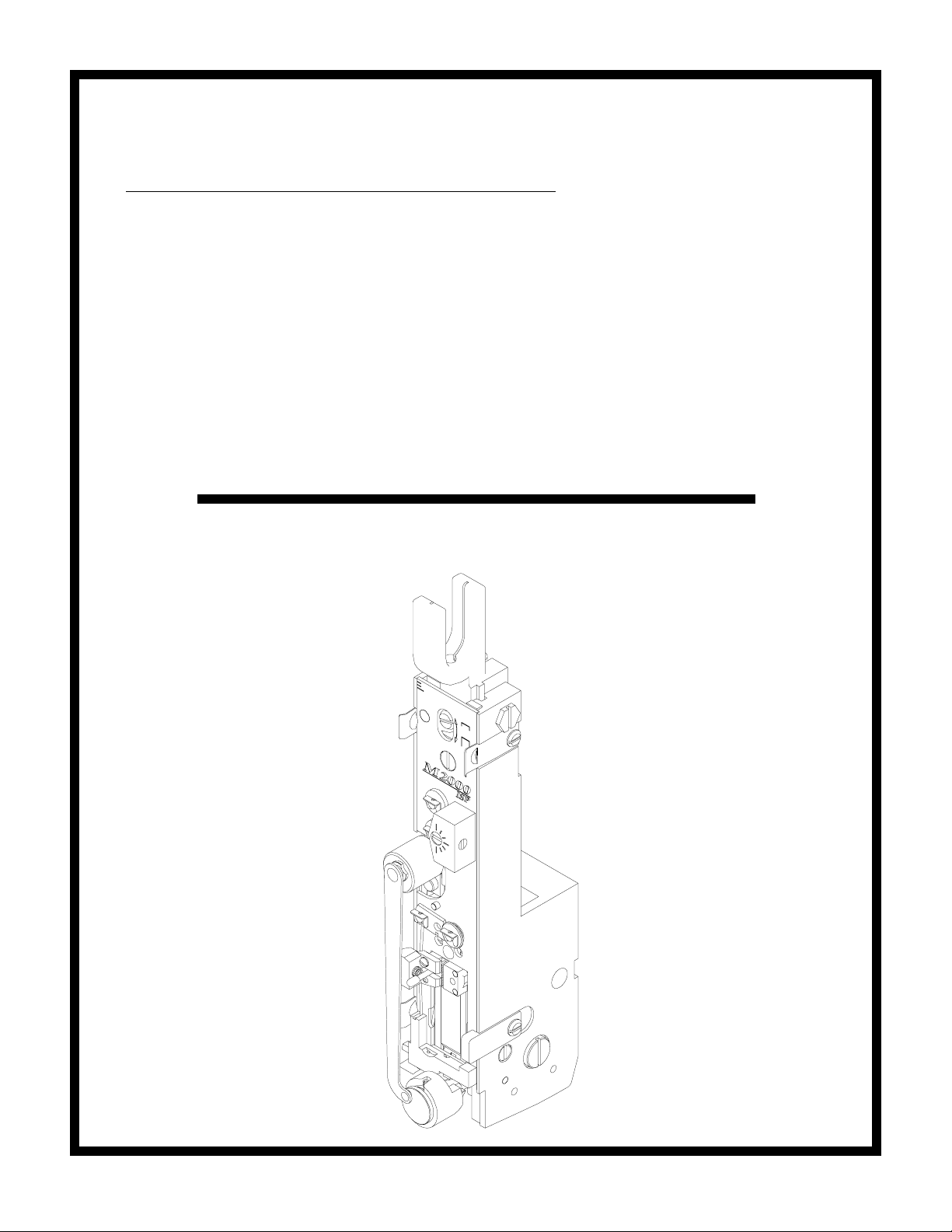
M2000 STITCHER HEAD
The M2000 Stitching Head has been engineered and developed to provide you with the finest equipment
available for your stitching needs. With proper care and maintenance it will give you years of satisfactory
efficient service. This manual shows you how to get top performance from your stitcher and is divided into 6
major sections.
Read the M2000 Manual thoroughly. Study it carefully. Best stitching performance will be assured, if all the
adjustments are made as instructed.
When ordering parts or requesting information, please state: Quantity required, part number, part name,
model, wire size, crown width, stitcher head part number, and stitcher head serial number.
Stitcher Head Serial Number____________________
Stitcher Head Part Number______________________
Stitcher Head Crown Width ____________________
Stitcher Head Wire Size____________________
Section 1

2
PRODUCT SPECIFICATIONS
Unit Weight: Lbs.
4.5 lbs.
Unit Envelope Size: Height Length Width
M2000 Head Without Wire Guide: 11 in. 3.12 in. 1.82 in.
Notes

3
DANGER
KEEP HANDS CLEAR OF
STITCHING AREA
CAUTION
FOR YOUR SAFETY, MAKE
SURE ALL COVERS ARE
PROPERLY IN PLACE BEFORE
OPERATING MACHINE
Section 2
SAFETY PRECAUTIONS
AND PROCEDURES
SAFETY
1. Make sure electrical power is turned off before
performing any adjustment or maintenance.
2. Keep hand, tools, hair, and clothing clear of
stitching area.
3. Become familiar with the moving components
of your machine. Keep fingers away from areas
that could pinch or cut.
4. Wear adequate safety equipment for eye and
face protection. Observe your plant safety
rules.
5. Practice good housekeeping in your work
area. Keep it as clean and uncluttered as
possible.
6. A well maintained machine is a safer machine.
Clean and lubricate the machine at regular
intervals. Check machine daily for broken or
worn parts. Replace as necessary. DO NOT
attempt to operate the machine if a part is
broken.
7. Route all electrical cables away from pedestrian
transportation lanes.
8. Make sure adequate safety guards and covers
are in place. If you are unsure how to safely
operate or maintain your Stitcher, contact your
Service Representative.

4
Section 3
ASSEMBLY,LUBRICATION,
INSTALLATION
Note:
These instructions must be followed to insure proper
installation, efficient operation and the prevention
of serious damage to your stitcher.
Before Unpacking:
Examine the outside of the crate or carton for any
visible damage. If damaged DO NOT UNPACK
THE STITCHER. Notify the carrier who deliv-
ered the stitcher.
After Unpacking:
Examine your stitcher carefully for any damage in
transit. If damaged, DO NOT INSTALL THE
STITCHER. Notify your nearest representative and
the carrier who delivered your stitcher.
Make certain that you get a signed copy of the
Carrier Inspectors Report of the damage incurred.
ASSEMBLY
1. Clamp or bolt the M2000 head to your machine
2. Install Wire Guide Spring into wire guide
bracket of M2000 Head.
THREADING WIRE AND
ADJUSTING WIRE
STRAIGHTENERS (See fig. 1)
1. Draw wire (Index A) by hand, from the coil.
2. Thread the wire through the slot (Index B) at
the end of the wire guide spring, , through the
wire guides (Index C), between the thin and
thick felt wire wipes (Index D), through the
upper wire straightener (Index E), and through
the lower wire straightener (Index F).
A (From wire coil)
C
H
G
J
K
F
B C
E
3. Release the rotator operating spring (Index H)
from the rotator and swing it to the left.
Remove Rotator (Index K).
4. Thread the wire between the tension pawl and
tension roll (Index G). Feed the wire through
the wire cutter lead-in hole (Index I) in the
bottom of the face plate.
5. Push grip post to left to open the grip (Index J).
Insert wire and release the post so that the grip
engages the wire for feeding into the rotator.
6. To check adjustment, hold open grip (Index J
and pull about 1 1\2 feet of wire from below
face plate. Cycle machine once by hand to cut
wire. Cycle machine again by hand to observe
wire straightness. The wire (Index L) should
point straight down, prior to being cut.
I
(CTTT2605 Scene 3, Scene 4)
Figure 1
D
L
5
7. Adjust the upper wire straightener, beginning at
position shown, (Index E) so that the wire points
straight down. Adjust the lower wire
straightener, beginning at the 3:00 o'clock
position, (Index F) so that the wire (Index L)
feeds straight down.
8. Replace the rotator and rotator operating spring.
NOTE:
When changing coils or wire sizes, check
straighteners to insure proper wire feed.
CAUTION
Do not operate stitcher until
operating instructions have been
read and understood-do not
operate stitcher at anytime without
work under the head.
FELT WIPE PADS
LUBRICATION
AND MAINTAINANCE:
(FIGURE 2)
IMPORTANT! In order for the stitchers to operate
properly, the felt wire wipes MUST be rotated and
dampened with SAE 20W oil before each new spool
of wire (50,000 to 70,000 stitches). Replace felt
pads when they become so dirty that they cannot be
rotated to a clean spot.
Figure 2
Dirty area of pads has been
slightly rotated so that a clean
area of pads can be used for the
next wire spool.
Rotate
1. After every wire
spool, rotate the
dirty area of the
pads slightly so that
a clean area can be
used for the next
wire spool.
(CTTT2605 Scene 7)
2. Dampen both pads
(about 30 to 40
drops) using an SAE
20W oil.
6
Typically, the 1/2 inch crown stitcher will run for
1,000,000 cycles without additional lubrication.
However, the following procedure used after each
spool of wire will assure optimum life and
performance. Use ISP lubricant #CA9640.
A. Inject lube into hole, or remove and lube shafts.
B. Wipe area clean and inject a small amount of
lube into cam area.
C. Remove rotator, wipe rotator clean and lube
rotator body.
D. Apply lube to rotator ramp.
STITCHING HEAD
LUBRICATION:
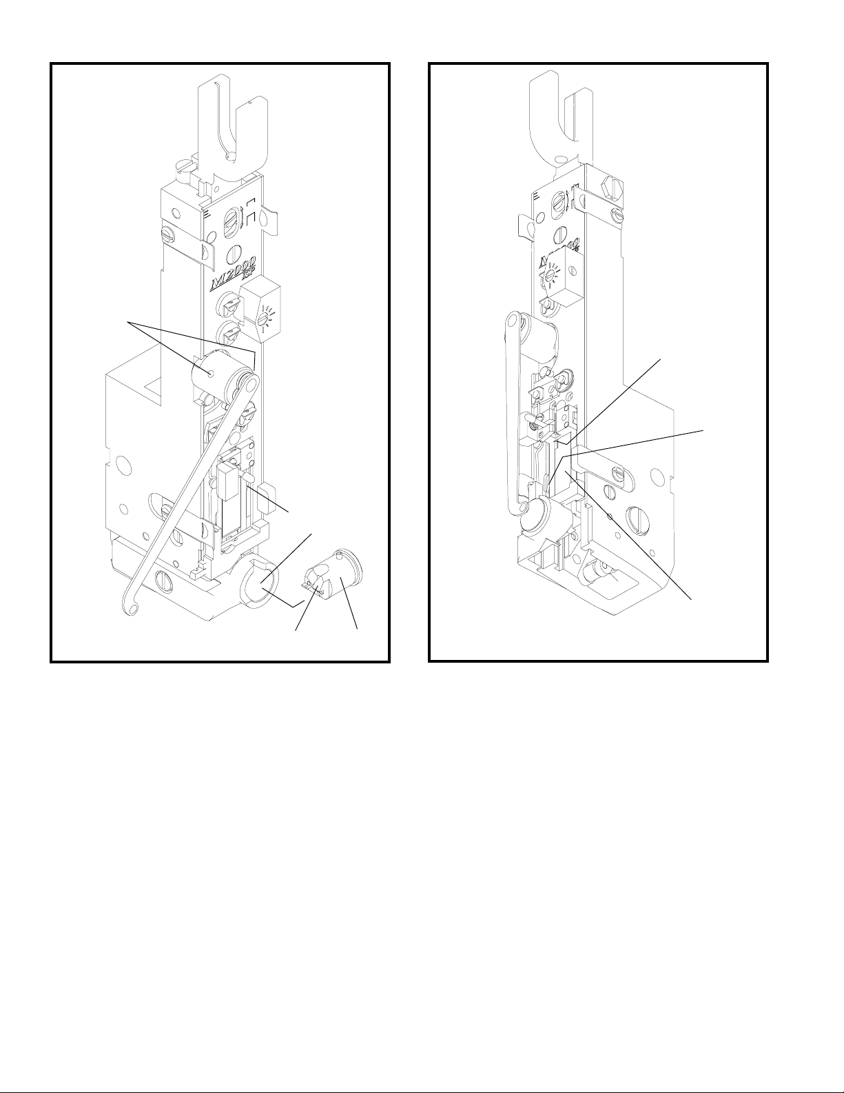
(FIGURES 3 & 4)
Figure 3
H
B
C
A
D
E
F
G
(CTTT2605 Scene 6)
E. Wipe clean inside of rotator holder.
F. Inject a small amount of lube into cam area of
driver bar.
G. Inject lube into cutter operating slide.
H. Wipe driver clean, and apply a light coating of
lube.
After prolonged use (or storage) accumulations of
wire dust, dirt, or other contaminants can mix with
the stitcher lubricant. This will reduce the
lubricant's effectiveness. The following procedure
is recommended every 1,000,000 cycles.
1. Disassemble the head and clean all parts.
2. Lightly lube all sliding surfaces using ISP
lubricant #CA9640.
3. Double check lube points A through H.
Figure 4
(CTTT2605 Scene 5)

7
Section 4
OPERATION
General:
After having properly installed and set up the ma-
chine, it is now ready for stitching. It is recom-
mended that each operator be instructed as to cor-
rect operating procedure and normal adjustments
necessary for varying work conditions.
WARNING
Prevent accidents by following these rules:
1. Do not put your hands near area to be
stitched when machine is operating.
2. Turn the power off when the stitcher
is not in use.
CAUTION
AVOID DAMAGE TO YOUR
STITCHER BY FOLLOWING
THESE RULES:
1. Never operate your stitcher with wire
feeding unless you have work material
between the clinchers and formers.
2. Do not drive one stitch on top of an
other.
Changing Work Thickness:
(Figure 5)
Changing work thickness will probably require a
change of the wire draw length used to make a
stitch. This is done by raising or lowering the face
plate. Change face plate position as follows:
1. Switch off power, loosen the face plate screw
(Index A).
2. Turn grip release lever (Index B) clockwise to
raise face plate for more wire draw or counter
clockwise to lower face plate for less wire draw.
NOTE: Raising face plate too high may: (1.)
Prevent the grip from closing and drawing wire;
(2.) Prevent proper compression resulting in a
loose stitch.
3. Retighten faceplate screw.
A
B
(CTTT2605 Scene 5)
Figure 5

8
A
C
D
E
Section 5
MAINTENANCE,TROUBLE
SHOOTING AND
ADJUSTMENTS
General
The M2000 Stitcher is a friction-type head which
depends on smooth sliding friction and proper tim-
ing to function correctly. Preventative maintenance
will go far to insure trouble-free operation. Avoid
production down time by keeping your stitcher lu-
bricated and in top working condition at all times.
Recommended Spare Parts
Like any equipment that has moving parts, certain
parts of your stitcher will be subjected to more
wear than others and require replacement. The fol-
lowing listing includes all the parts required for
minimum maintenance and good operation.
PART NAME QTY.
Wire Cutters 2
Grip 1
Grip Spring 1
Tension Roll Clip 2
Rotator 1
Clincher Points 2
Caution
MAKE ALL ADJUSTMENTS
WITH THE POWER OFF AND
THE STITCHING HEAD IN
NEUTRAL POSITION! (Fig. 6)
In neutral position, the wire grip assem-
bly (Index A) is stopped at the top of the
slot in the face plate.
Stitching Adjustments
Best stitching performance will be assured if all
adjustments are made so that you get the following
results:
1. Good Cut-Off
2. Uniform Wire Draw
3. Equal Leg Length
4. Proper Clincher Alignment
5. Sufficient Compression
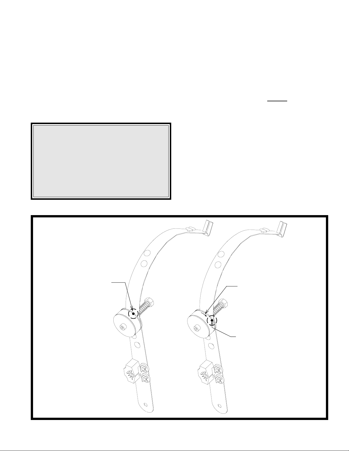
To Equalize Both Legs of Stitch
(Figure 7)
1. Loosen the wire guide locking bolt (Index C).
2. Turn adjusting screw (Index D) clockwise to
shorten left leg of stitch; counter clockwise to
lengthen left leg.
3. Tap bracket (Index E) down before tightening
screw (Index C).
(CTTT22605 Scenes 5 & 9)
(CTTT2605 Scene 8)
Figure 6 Figure 7
Table of contents
Other iSP Sewing Machine manuals


