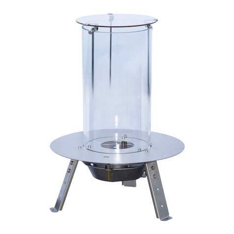
Italkero QUADRO 40 Instruction Manual

0063
CU3238
Gas heating
- rebox insert -
INDOOR USE
QUADRO
40
INSTALLATION and
MAINTENANCE

40
INDOOR QI40A0 MI000
ACCESSORIES
Gas supply valve KIT
Electrical power supply KIT
Wood KIT
Stone KIT
Sheet metal cover (painted stainless steel)
Connection cable for smoke extractor
Wall control (wired)
GENERAL
2
RANGE
Our equipment is conforming with:
• Regulations (UE) 2016/426 (GAR)
• Electromagnetic Compatibility Directive 2014/30/UE
• low Voltage Directive 2014/35/UE
• Regulations RAEE 2019/19/UE
COMPLIANCE

Provided that it is fitted in accordance with the Manufacturer's instructions, this appliance benefits
from the statutory warranty.
WARRANTY
Dear Technician,
You are fortunate to have available an appliance capable of ensuring maximum and lasting
aesthetic well-being ensuring high reliability, efciency, quality and safety
With this manual our intention is to provide you with the information we consider necessary for
correct and easier installation of the appliance, adding to your proven expertise and technical
expertise.
Enjoy working with the appliance and thank you again.
The Manufacturer
Before contacting the authorised warranty activation service center, check that:
- the appliance is functional and with all its components installed (possible glass protection, blocks or pebbles,
valve housing with door, suction hood, pipe and fume exhaust end).
- all parts of the appliance can be inspected and therefore without its nal decorative coating.
- it is properly connected to gas and electricity (in case of power supply accessory)
3
GENERAL

General warnings 5
Basic safety rules 5
Description of the appliance 6
Identication 6
Pre-installation 7
- types of gas 7
- electrical connection 7
- gas connection 8
- compliance with the Standards 9
Structure 11
Receiving the product 12
Dimensions and weights 13
Installation 14
- xing 14
- housing compartment 15
- combustion fume exhaust 15
- ue 16
- fume exhaust 17
- safety distances 18
Commands 19
First ignition 21
Adjustments 23
Wood or stones 24
Special installations 25
Useful information 26
Warranty 27
TABLE OF CONTENTS
4GENERAL
In same parts of the book there are used these symbols:
Attention: it used to underline particular caution or actions.
Prohibited: it used to underline the actions that don’t half to
be executed.

5
GENERAL
We remind you that the use of products that use fuels
and electricity involves compliance with a number of
basic safety rules such as:
Children and unassisted disabled persons are
prohibited from using the appliance.
It is forbidden to operate electrical devices or
appliances such as switches, appliances, etc. if
there is an odour of fuel or of combustion fumes or
unburnt substances.
In this case:
• ventilate the room by opening doors and windows;
• close the fuel shut-off device;
• promptly involve the Manufacturer's Technical
Assistance Service or professionally qualied
personnel.
Any cleaning operation before complete cooling of
the appliance is prohibited, therefore disconnect
the power supply by turning the main switch of the
system to "OFF” or unplug (if present).
It is forbidden to pull, detach or twist the electrical
cables leaving the appliance even if it is disconnected
from the mains power supply.
It is forbidden to place on the appliance objects such
as towels, dishcloths, doilies, etc. that could cause
malfunctions or even danger.
It is forbidden to disperse, discard or leave within
reach of children the packaging material (cardboard,
staples, plastic bags, etc.) as it can be a potential
source of danger and pollution.
After removing the packaging ensure the integrity
and completeness of the contents. In case of non-
compliance, contact the Agency that sold the appliance.
Installation of the appliance must be carried out by a
company authorised in accordance with the Law. At
the end of the work, it must issue to the owner the
declaration of conformity of installation carried out in
a workmanlike manner, that is in compliance with the
current Standards and the indications provided by
the Manufacturer in the manual for the installer that
is supplied with the product
The appliance is designed for the use intended by
the Manufacturer for which it was manufactured.
Any contractual and non-contractual liability of
the Manufacturer for damage caused to persons,
animals or property, due to errors in installation,
adjustment and maintenance or improper use of the
appliance is excluded.
In the case of non-use for a lengthy period:
• turn the main switch of the appliance to “off”;
• turn the main switch of the system, if present, to
“off” or disconnect the plug from the power socket
if present;
• remove the batteries from the control unit on the
appliance;
• turn off the gas valvve.
This manual is an integral part of the appliance and
must therefore be stored carefully and must ALWAYS
accompany the appliance even if it is sold to another
owner or user or transferred to another system.
In case of damage or loss, request another copy
from the Technical Assistance Service of the Local
Manufacturer.
This appliance is equipped with a re bed with
embers and ceramic blocks containing refractory
ceramic ber, consisting of articial bers of vitreous
silicate. It is therefore advisable to minimise the
release of dust during handling of these materials.
Prolonged exposure to these materials may cause
irritation to the eyes, skin and respiratory system. In
case of replacement of one of the components of the
embers or blocks, it is advisable to seal the removed
parts in a bag and to take them to a waste disposal
centre.
ATTENTION! BEFORE TURNING ON THE
APPLIANCE, CAREFULLY READ ALL THE
INSTRUCTIONS AND WARNINGS CONTAINED IN
THIS MANUAL.
The appliance can be used indoors in both domestic
and commercial environments.
GENERAL WARNINGS
BASIC SAFETY RULES

DESCRIPTION OF THE APPLIANCE
IDENTIFICATION
This appliance is for decorative purposes.
This appliance is designed for decorative purposes
in compliance with the applicable European standard
EN509, for this reason the performance has not been
evaluated as the usual appliances for heating.
The appliance can be identied by:
- Packaging label
it shows the name of the product, the code, the serial
number and the type of gas used.
- the Technical Plate
it shows the serial number, the model and the main
technical-performance data.
- The gas fitting plate
It displays the name of the gas for which the appliance
has been set-up and adjusted.
Any type of tampering for its operation with another
type of gas is to be considered dangerous and the
Manufacturer cannot be held liable for any damage to
persons or property.
Tampering with any parts of the appliance or compo-
nents will result in the immediate loss of all warranty
rights offered by legal obligations.
Spare parts and/or technical interventions
require exact identication of the model of
equipment for which they are intended.
Tampering with, the removal or absence of the
Technical Plate or anything else will impede
safe identication of the product making any
installation or maintenance operation difcult.
6GENERAL

ELECTRICAL CONNECTION
The appliance is always supplied ready to operate
with 4 x 1.5VDC AA batteries so it does not require
connection to the mains.
The power supply accessory allows the appliance to
operate with 230VAC mains voltage (1).
In this case it will be necessary to have an electrical
outlet within a radius of 1.5 meters.
If this accessory is used, the batteries are
automatically excluded and it is therefore
necessary to remove them, to avoid their inactivity
causing the release of liquids and damage to the
control board.
category 3P 3B/P 3+ 2E 2H 2E(R)
GAS Propane Butane -
Propane
Butane -
Propane
Methane Methane Methane
TYPES OF GAS
Before proceeding with installation, check that the data
on the label of the appliance corresponds to the type
and pressure of the gas supplied.
Gas installation and connection must be carried out
by qualied personnel, in full compliance with the
applicable Standards.
Make sure that the gas inlet duct has the appropriate
ow rate and that it has a shut-off valve near the
appliance and is easy to access.
PRE-INSTALLATION
7
GENERAL
1

gas 40
Rated power (p.c.i.) NAT 15,5 kW
GPL 14,5 kW
Number of main burner injectors 1 nr.
Main burner injector diameter NAT 3,30 mm
GPL 1,98 mm
Pilot burner injector NAT 0,35 mm
GPL 0,25 mm
Gas pipe diameter
1/2‘ M/F - extendible from 75 to 130
mm
GAS CONNECTION
The appliance is equipped with a table that uniquely identies it.
The gas connection must be created with a metal pipe directly on the gas valve.
paste here
adhesive plate
8GENERAL

COMPLIANCE WITH THE STANDARDS
For installation of this appliance it is always necessary to comply with the rules in force in the country in which it is
to be used.
Elements to be respected for GAS CONNECTION:
For LPG appliances, all rooms with a oor below the external pedestrian oor or communicating with
this type of environment are excluded.
• Pipe size with reference to the thermal ow rate of the appliance.
• The positioning of the gas pipes must generally allow inspectability and maintenance at any time in the event of
malfunctions.
NATURAL GAS · STEEL PIPE
ow rate by volume (m3/h at 15°C) with density 0.6 with a pressure loss of 1.0mbar
Threading
(inches)
3/8 1/2 3/4 1 1 -
1/4
1 -
1/2
2
Inner
diameter (mm)
13.2 16.7 22.5 27.9 36.6 42.5 53.9
Thickness
(mm)
2 2.3 2.3 2.9 2.9 2.9 3.2
pipe length
(m)
ow rate
volume (m3/h)
2 3.16 5.92 13.11 23.26 47.97 71.46 -
4 2.15 4.03 8.92 15.83 32.64 48.62 91.63
8 1.46 2.74 6.07 10.77 22.21 33.08 62.35
10 1.29 2.42 5.36 9.51 19.62 29.23 55.08
15 1.03 1.93 4.28 7.59 15.66 23.33 43.97
20 0.88 1.65 3.65 6.47 13.35 19.89 37.47
25 0.78 1.46 3.22 5.72 11.79 17.57 33.11
30 0.70 1.31 2.91 5.17 10.66 15.87 29.92
40 0.60 1.12 2.48 4.40 9.08 13.53 25.50
50 0.53 0.99 2.19 3.89 8.02 11.95 22.52
75 0.42 0.79 1.75 3.11 6.41 9.54 17.98
100 0.36 0.67 1.49 2.65 5.46 8.13 15.33
NATURAL GAS · COPPER PIPE
ow rate by volume (m3/h at 15°C) with density 0.6 with a pressure loss of 1.0mbar
External
diameter (mm)
12 14 15 16 18 22 28
Inner
diameter (mm)
10 12 13 14 16 20 26
Thickness
(mm)
1111111
pipe length
(m)
ow rate
volume (m3/h)
2 1.51 2.45 3.04 3.70 5.28 9.57 19.27
4 1.03 1.67 2.07 2.52 3.59 6.51 13.11
8 0.70 1.14 1.41 1.71 2.44 4.43 8.92
10 0.62 1.00 1.24 1.51 2.16 3.92 7.88
15 0.49 0.80 0.99 1.21 1.72 3.13 6.29
20 0.42 0.68 0.84 1.03 1.47 2.66 5.36
25 0.37 0.60 0.75 0.91 1.30 2.35 4.74
30 0.33 0.54 0.67 0.82 1.17 2.13 4.28
40 0.29 0.46 0.57 0.70 1.00 1.81 3.65
50 0.25 0.41 0.51 0.62 0.88 1.60 3.22
75 0.20 0.33 0.41 0.49 0.71 1.28 2.57
100 0.17 0.28 0.35 0.42 0.60 1.09 2.19
LPG · STEEL PIPE
ow rate by volume (m3/h at 15°C) with density 1.69 with a pressure loss of 2.0mbar
Threading
(inches)
3/8 1/2 3/4 1 1 -
1/4
1 -
1/2
2
Inner
diameter (mm)
13.2 16.7 22.5 27.9 36.6 42.5 53.9
Thickness
(mm)
2 2.3 2.3 2.9 2.9 2.9 3.2
pipe length
(m)
ow rate
volume (m3/h)
2 2.61 4.89 10.84 19.23 39.66 59.09 111.35
4 1.78 3.33 7.37 13.09 26.99 40.20 75.76
8 1.21 2.27 5.02 8.90 18.36 27.35 51.55
10 1.07 2.00 4.43 7.87 16.22 24.16 45.54
15 0.85 1.60 3.54 6.28 12.95 19.29 36.35
20 0.73 1.36 3.02 5.35 11.04 16.44 30.98
25 0.64 1.20 2.66 4.73 9.75 14.52 27.37
30 0.58 1.09 2.41 4.27 8.81 13.12 24.73
40 0.49 0.93 2.05 3.64 7.51 11.19 21.08
50 0.44 0.82 1.81 3.22 6.63 9.88 18.62
75 0.35 0.65 1.45 2.57 5.30 7.89 14.87
100 0.30 0.56 1.23 2.19 4.51 6.72 12.67
LPG · COPPER PIPE
ow rate by volume (m3/h at 15°C) with density 1.69 with a pressure loss of 2.0mbar
External
diameter (mm)
12 14 15 16 18 22 28 35
Inner
diameter (mm)
10 12 13 14 16 20 26 33
Thickness
(mm)
11111111
pipe length
(m)
ow rate
volume (m3/h)
2 1.25 2.03 2.51 3.06 4.37 7.92 15.94 30.09
4 0.85 1.38 1.71 2.08 2.97 5.39 10.84 20.48
8 0.58 0.94 1.16 1.42 2.02 3.66 7.38 13.93
10 0.51 0.83 1.03 1.25 1.79 3.24 6.52 12.31
15 0.41 0.66 0.82 1.00 1.43 2.58 5.20 9.83
20 0.35 0.56 0.70 0.85 1.21 2.20 4.43 8.37
25 0.31 0.50 0.62 0.75 1.07 1.95 3.92 7.40
30 0.28 0.45 0.56 0.68 0.97 1.76 6.54 6.68
40 0.24 0.38 0.48 0.58 0.83 1.50 3.02 5.70
50 0.21 0.34 0.42 0.51 0.73 1.32 2.67 5.03
75 0.17 0.27 0.34 0.41 0.58 1.06 2.13 4.02
100 0.14 0.23 0.29 0.35 0.50 0.90 1.81 3.42
9
GENERAL

Aspects to be respected for INSTALLATION:
Can be installed in any type of indoor space except
for garages, warehouses containing combustible/
ammable material. The internal installation
environment requires ventilation openings, however, it
must be possible to be ventilated with doors or windows
communicating externally and openable.
It is forbidden to install the appliance in rooms
where another wood-red heat generating
appliance has already been installed.
• Generally not permitted are rooms, garages,
ammable material stores, bathroom and the presence
of other gas/wood appliances that draw air from the
environment for combustion,
• The ventilation/airing of the room must consider
that the appliance is of the BAS type, therefore for
correct operation it draws the combustion air from the
environment in which it is installed and it is necessary
to provide openings directly to the outside.
External air intake
the Safety Regulations provide for an external air
intake of MIN 6 cm2for each kW of power installed
in the environment: e.g. for 10 kW an opening with a
surface of at least 60 cm2is required but it must be
increased to at least 100 cm2.
IMPORTANT: for safety reasons and in
compliance with current regulations, the
opening must never be less than 100 cm2.
As an alternative to the outdoor air intake, it is possible
to connect the appliances to a forced ventilation sys-
tem to guarantee continuous air exchange, necessary
for safety but also for the correct operation of the appli-
ance.
10 GENERAL

1
2
3
7
4
18
17
16
5
3
213
15
814
9
19
8
7
12
12
10
11
10
6
6
1 - Burner cover
2 - Burner
3 - Frame
4 - Infrared receiver
5 - Ignition unit
6 - On/Off valve switch
7 - Flame control board
8 - Gas valve
9 - MAX adjustment screw
10 - Burner gas pipe
11 - Thermal switch for thermocouple
12 - Pilot gas pipe
13 - 6V DC power socket
14 - MIN adjustment screw
15 - Mains gas inlet
16 - Ignition electrode
17 - Pilot with CO safety device
18 - Thermocouple
19 - Infrared remote control
STRUCTURE
INSTALLER 11

RECEIVING THE PRODUCT
The appliance is supplied with:
no. 1 Device with remote valve
no. 1 Standard On/Off remote control
no. 1 Gas supply pipe
no. 1 Document envelope:
no. 1 User instructions manual
no. 1 Installer manual
no. 1 Warranty certicate
no. 1 Warranty labels
12 INSTALLER

D
E
40
A 92 mm
B 410 mm
C 410 mm
D 388 mm
E 83 mm
Fmm
Gmm
Hmm
I (gas pipe) 1/2‘ M/F - extendible from 75 to 130 mm
L 1700 mm
M (receiver) 1000 mm
net weight 9,5 Kg
gross weight Kg
DIMENSIONS AND WEIGHTS
13
INSTALLER

14 INSTALLER
5 mm
5 mm
5 mm
1
1
X
1
INSTALLATION
The appliance in your possession includes:
• Burner body incorporated in the structure provided
for the recess
• Gas valve connected to the burners with hoses of 1m
length for mod.40 - 60 and 1.7m for the others (from
the center of the burners)
• Gas valve support bracket for electronic burner
management
• Remote control for remote management of
the burners: on, MAX/MIN flame adjustment
and off.
There are no functional and structural parts to
assemble before installation of the individual
appliance.
FIxING:
A) ONE APPLIANCE: create the compartment (1) to
house and secure the appliance.
Secure the appliance using the holes on the
frame.
This compartment must be larger than the rebox in
order to guarantee an empty gap of 5mm along the
entire perimeter of the appliance.
This cavity will be used both for convenient insertion
and for quick removal of the appliance in case of any
future repairs.
• Create a housing compartment for the gas valve,
close the compartment with a door (accessory) or
create one, to avoid easy access and to ensure greater
protection of the valve.
• Anchor the valve support bracket in the compartment
created, securing it with appropriate screws.
• Be sure to have left the technical data plate easily
accessible to anyone who will be called in to work on
the appliance.
B) MULTIPLE APPLIANCES: create the compartment
(1) to house and secure all the appliances.
Secure each appliance using the holes on the
frame.
This compartment must be larger than the composition
of the braziers in order to guarantee an empty gap of
5mm along the entire perimeter of the composition.
This cavity will be used both for convenient insertion
and quick removal of the appliances in case of any
future repairs.
• Make sure that the appliance rests stably and
horizontally in the compartment created and
provide at least one screw anchor at the base of the
compartment.
• Create a housing compartment for the gas valve, close
the compartment with a door (Price List accessory) or
create one, to avoid easy access and to ensure greater
protection of the valve.
• Anchor the valve support bracket in the compartment
created, securing it with appropriate screws.
• Be sure to have left the technical data plate easily
accessible to anyone who will be called in to work on
the appliance.
For the installation of two or more appliances,
refer to the Special Installations Chapter.

MIN
170mm
MIN
5mm
40
MIN width 700 mm
MIN depth 700 mm
MIN inclination
37°
MIN / MAX distance between
the re bed and the hood
100 / 500 mm
320
320
1.5
30
48 265
265
OPTIONAL
HOUSING COMPARTMENT
The appliance is to be considered recessed, so it is
necessary to create a compartment in which to place it
and then x it using the holes on the frame.
The materials of which the compartment must be compo-
sed, vertical sides and horizontal plane, must be resistant
to minimum temperatures of 80°C plus ambient tempe-
rature: the materials that by their nature are considered
ammable or labelled as such must be avoided.
Install the appliance avoiding the use of
cement or other adhesives for construction
that may prevent its possible removal.
The cladding counterwalls, all self-supporting,
complete installation of this appliance and
must be constructed with non-ammable materials
in full compliance with the current regulations.
Infra-red receiver
The housing compartment of the gas valve must be
closed with a door (accessory) to prevent free access
and to protect the valve.
On the accessory door frame, the Manufacturer has
provided a slit to house the receiver of the appliance.
If you do not want to use the accessory door, you can
create one using reproof materials.
In this case the receiver must be positioned immedia-
tely next to the appliance but it is necessary to:
- avoid positioning it along the entire surface of the
burner or along the entire edge of the appliance for a
thickness of 1 cm.
- avoid direct exposure to sources of glare or sunlight.
- do not place it behind any obstacle (glass, sheet me-
tal, wood, stone, etc.)
ExHAUST COMBUSTION FUMES
The combustion products must be discharged outside
the room where the appliance is installed.
The ue gas can be discharged in different ways de-
pending on the conditions of the room and the installa-
tion of one or more appliances in the same room.
Elements common to different types of ue:
• the presence of a conveyor hood with minimum di-
mensions according to the following table.
• the minimum diameter of the ue must be MIN 180mm
(minimum equivalent section 255cm2)
• The temperature of the combustion products can
reach 400°C so only use materials that are resistant to
these temperatures.
The expulsion of combustion products must take ac-
count the type of roof and above all must be in compli-
ance with national rules to:
• avoid defects of poor circulation
• avoid a situation whereby the effect of the wind pre-
vents draft
• avoid discharging into areas harmful to neighbours
INSTALLER 15

GAS
IN
MIN 2m
1
MIN 2m
2
A B
MIN 0,5m
3
C
GAS
IN
5
6
7
8
4
FLUE
A.ExISTING FLUE
• Clean the existing ue before installing the appliance
and before carrying out a ue gas evacuation test, ac-
cording to the national regulations.
• Make sure that the ue is dedicated only to the appli-
ance being installed and that it is not shared with other
appliances already installed.
• Minimum vertical development 2 metres.
• Any restrictors (1) present along the path of the com-
bustion products must be removed or xed in full open
mode.
B. VERTICAL FLUE CREATION
• Minimum vertical development 2 metres.
• Protect the ue from rain or dust penetration from
above with a cover terminal (2) that does not obstruct
the leakage of combustion products.
C. HORIzONTAL FLUE CREATION
• Minimum vertical development of 0.5 meters
• Horizontal development as required but with an elec-
tromechanical extractor obligation (3*, accessory not
listed).
(3*) the electromechanical extractor must guarantee a
pressure difference during the suction phase ranging
from 40 to 80 Pascal, depending on the route of the
ue.
In addition, the extractor must have the function of ad-
justing the rotation speed, as it is always the instal-
ler's responsibility to ensure stability of the ame and
to avoid defects such as tearing or extinguishing the
main burner with the extractor in operation.
it is possible buy the connection cable with the smoke
extractor (Price List accessory).
This accessory offers the possibility of activating the
fan of the extractor, when the power on command of
the appliance is given.
The Manufacturer suggests the purchase of extrac-
tors equipped with smart systems that detect any fan
malfunctions and interrupt the ow of gas.
Operating diagram:
a) when switching on (4) the receiver of the appliance
(5) will give the ON pulse to the fan (6);
b) the smart system or the pressure switch (7), will ver-
ify the correct operation and the correct suction;
c) only afterwards will the solenoid valve opening com-
mand (8) be given.
In the event of a fan malfunction (6), the smart system
or pressure switch (7) will interrupt the current on the
solenoid valve (8) which will immediately close the gas
ow to the appliance (5).
The interruption due to faults or anomalies in one of
the illustrated elements will interrupt the operating cy-
cle described in the gure, ensuring adequate safety.
16 INSTALLER

SUCTION HOOD
This appliance is equipped with an atmospheric burner
with a naked ame TYPE B combustion chamber.
Oxidising air is drawn directly from the room where the
appliance is installed.
To ensure proper ue gas evacuation:
• adequate in the minimum dimensions specied in the
table (Chap. Combustion fumes discharge).
• each side of the hood must protrude 20cm from each
side of the appliance.
• minimum inclination (see table in the Cap. Combusti-
on fumes discharge).
• MIN area of the exhaust pipe must be 255cm2.
• the position of the exhaust pipe must be in the center
of the hearth surface.
The appliance should not be installed only in
the center of the hood, it can be decentralized
but always within the area covered by the hood.
GAS
IN
INSTALLER 17

SAFETY DISTANCES
Maintain a distance of at least 1m (1) between
the appliance and objects in combustible
or ammable material: wooden furniture and
furnishings, ornaments, curtains, etc.
Do not approach or put the appliance in direct
contact with combustible, heat-sensitive or
ammable materials: furniture, beams, ceilings,
curtains, etc.
- DO NOT use accessories or components not
provided by the Manufacturer for placement as they
could create serious danger.
- Do not obstruct the suction/discharge terminal of the
appliance with loose linen or belts.
Dimensions of openings for ambient ventilation
The openings must guarantee an air ow from the
outside of at least 2m3/h for each kW of power of the
appliance.
Flame protection barrier
In this appliance there are naked ames. It is ad-
visable to use a protective barrier for children, the
elderly and the disabled.
The protective barrier is not supplied with the
appliance.
To create a protective barrier, it is necessary to comply
with the following characteristics:
• non-ammable material.
• provide openings that allow the correct amount of air
to pass through the rebox (MIN 10cm high along the
entire perimeter of the appliance).
• installed in such a way as not to interfere with the
pulling of the ue over the rebox.
• xed to the coating such as to avoid falling on the
appliance.
18 INSTALLER

COMMANDS
6
7
8
1 4 52 3
91011
12
1 - Adjustment knob
2 - MAX gas adjustment screw
3 - Valve Connector/Flame control board
4 - Piezoelectric power button (manual)
5 - O-1 switch
6 - Magnet leg for manual operation
7 - Manual intervention position knob
8 - Piezoelectric connection cable connector (manual)
9 - Flame control board
10 - Valve Connector/Flame control board
11 - 6V DC power socket
12 - Cable to be disconnected from the control unit and connected to position 8
Automatic operation position with REMOTE CONTROL
MANUAL operation position
TECHNICAL ASSISTANCE 19

5
4
2
3
1
REMOTE CONTROL
This appliance is equipped with an infrared remote
control, for safety reasons in compliance with current
regulations.
To switch on the appliance, point the remote
control directly at the sensor at A maximum
distance of 3m avoiding interference with front
light sources or obstacles.
1 - Red LED, Transmission
2 - Off
3 - On (3 + 5)
4 - lower ame
5 - ame riser (3 + 5)
TECHNICAL ASSISTANCE
20
Table of contents
Other Italkero Indoor Fireplace manuals