IVAR UNIMIX User manual

UNIMIX
IVAR_UNIMIX_E_DE.indd 1 05-11-2008 10:04:07

1. 3-Wege-Mischventil, Steuerung durch Thermostat oder Motor
möglich (ohne dass ein Austausch des Einsatzes erforderlich ist)
1a. Thermostatkopf mit Ferntauchsonde,
Einstellbereich 30 -50°C
1b. Elektrothermischer Kopf, 24 V AC, Proportionalsignal
0-10 V
1c. Servo-Linearmotor 24 V AC, Proportionalsignal 0-10 V
2. Primär-Bypass für Hochtemperaturkreis
3. Ausgleichsventil (Bypass für Sekundärkreis)
4. Schacht für Tauchsonde des Thermostatkopfes
5. Temperaturanzeige/Manometer
6. Automatisches Entlüftungsventil
7. Absperrventile auf Zuleitung (7a) und Rückleitung (7b)
8. Füll- und Ablassarmatur
9. Manuelles Entlüftungsventil
10. Umlaufpumpe (nicht geliefert)
11. Hochtemperatur-Verteilersatz mit einfachen Verteilern (11a)
oder mit absperrbaren Verteilern (11b), einschließlich:
12. zwischen 0,2 - 0,6 bar verstellbarer Überdruck-Bypass
13. Füll- und Ablassarmatur
14. Sicherheitsthermostat mit Tauchsonde, Einstellbereich
20 - 60°C
14a. Fest kalibrierter Sicherheitsthermostat (55°C)
T1-T2 Thermometer
1. three-way mixing valve, thermostatically operated or motor-
driven (without having to replace the insert)
1a. thermostatic head with remote immersion probe,
adjustment field 30÷50°C
1b. electro-thermal head 24 VAC proportional 0-10 V
1c. axial servo-motor 24 VAC proportional 0-10 V
2. primary bypass for high temperature circuit
3. balance valve (bypass for secondary circuit)
4. pit for the thermostatic head immersion probe
5. temperature-pressure gauge
6. automatic air breather valve
7. cut-out valves on delivery (7a) and return (7b)
8. fill-empty cock
9. manual air breather valve
10. circulator (not supplied)
11. high temperature distribution kit with simple manifolds (11a) or
with shutoff manifolds (11b) including:
12. adjustable over-pressure bypass 0.2 - 0.6 bar
13. fill-empty cock
14. safety thermostat with adjustable immersion probe 20÷60°C
14a. fixed calibration safety thermostat (55°C)
T1-T2 thermometers
Fig. 1
IVAR_UNIMIX_E_DE.indd 2 05-11-2008 10:04:10

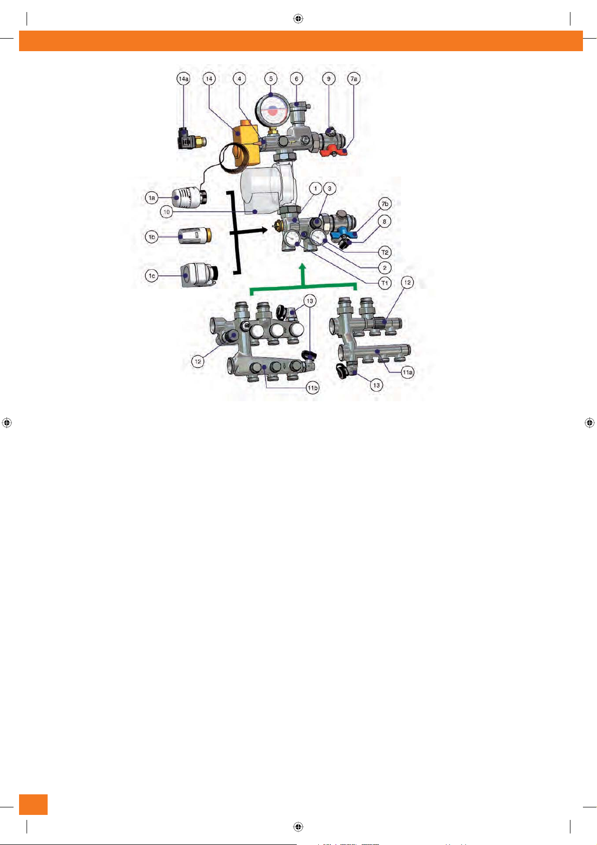
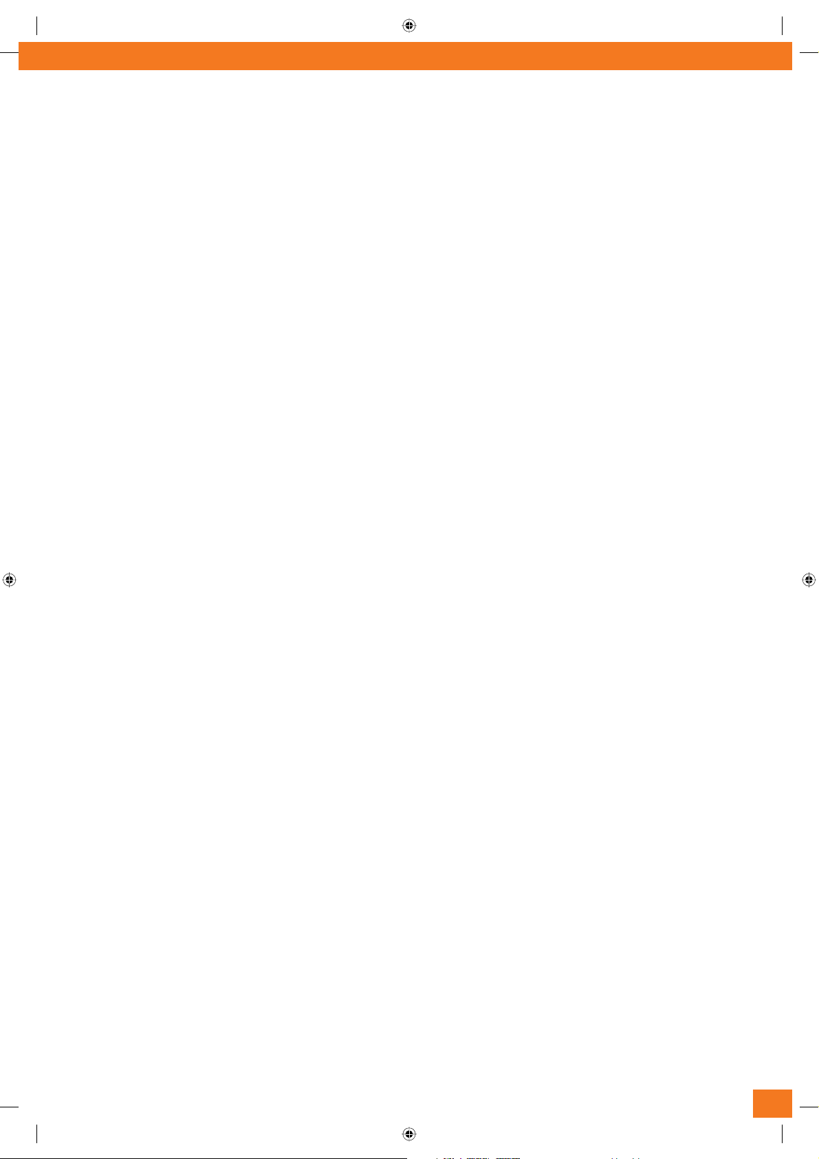
UNIMIX is an innovation in the panorama of floor-mounted system adjustment groups. This mixing system sets the temperature of the
fluid in the primary circuit (boiler) to the adjustable value required in the secondary circuit (heating panel).
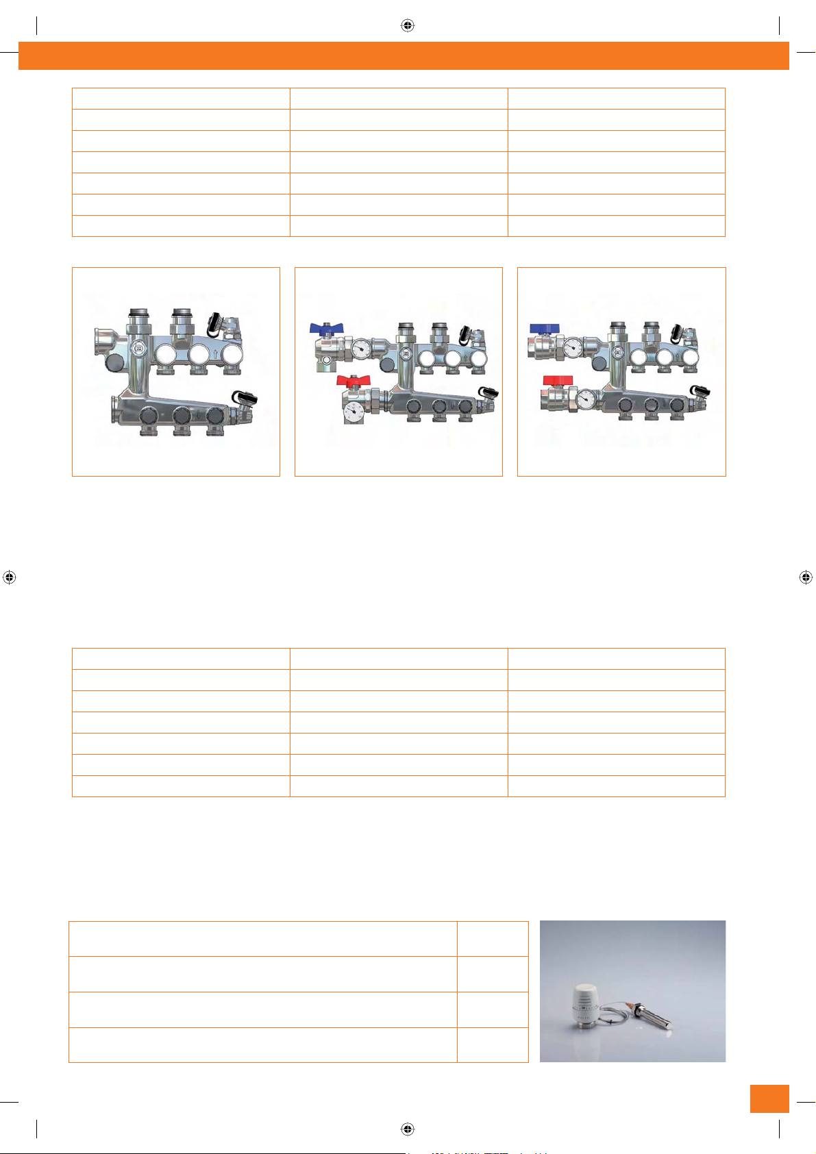
UNIMIX is a modular group that can be connected directly and easily to our manifolds for panelled plant. Using a circulator with 130 mm
centres allows connection to our manifolds mounted on supports with 200 mm centres, while a circulator with 180 mm centres requires
the use of 250 mm brackets (Article AC 611).
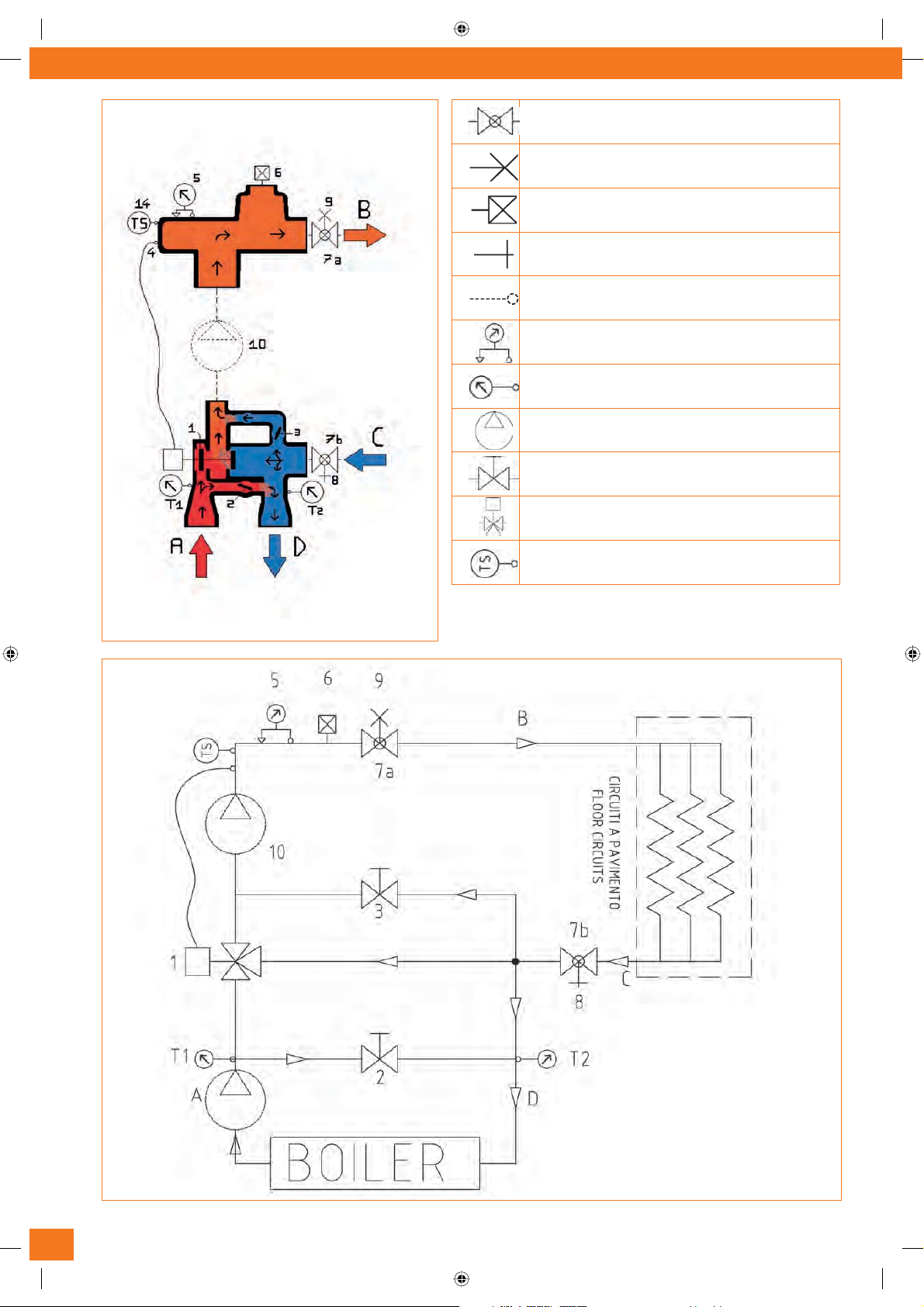
The system can be easily powered from below or from the side by means of our angle ball valves AC 655, thereby ensuring for installa-
tion technicians convenient assembly in all possible configurations.
The versatility of this group is highlighted in the case of mixed-circuit systems: high temperature (radiator system) and low tempera-
ture (panelled heating system).
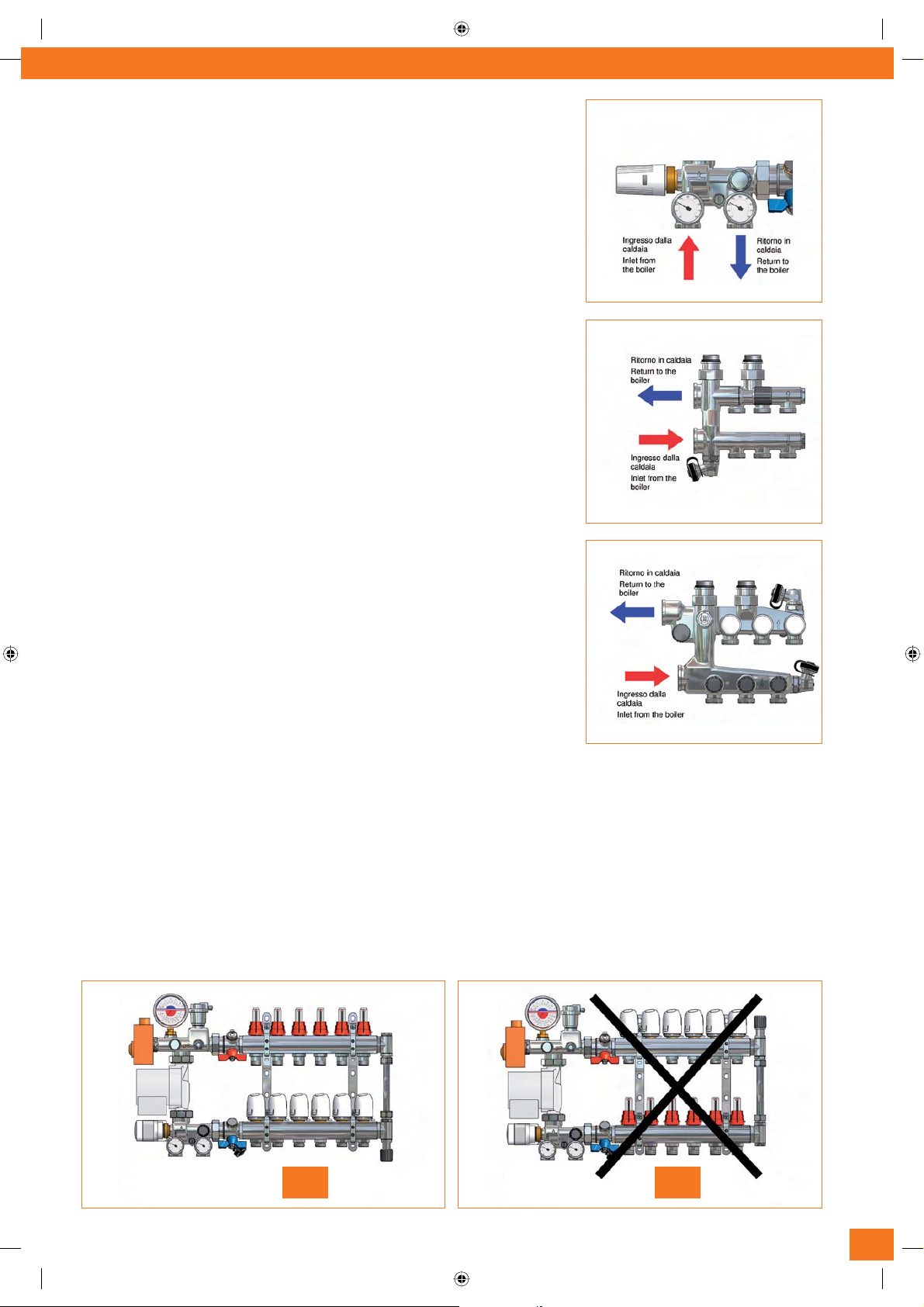
This is the classic example in homes with floor general heating and bathroom radiators (towel warmers, etc.). To implement this
system, simply connect to the UNIMIX inlet the new high temperature distribution kit including fill-empty cocks, delivery and return
manifolds with simple branches for radiators, the over-pressure differential valve.
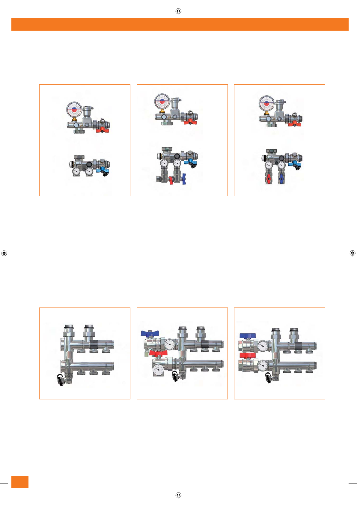
There are two different high temperature systems:
1. High temperature kit with micrometric balancing valves and electro-thermal heads driven inserts with M24x1.5 or Eurokonus
off-takes. Those kits are also available complete of straight or angle ball valves for the connections to the primary circuit..
2. High temperature simple distribution manifold with M24x1.5 or Eurokonus off-takes. Those kits are available also complete
of straight or angle ball valves for the connections to the primary circuit.
The UNIMIX system can operate in the following two ways:
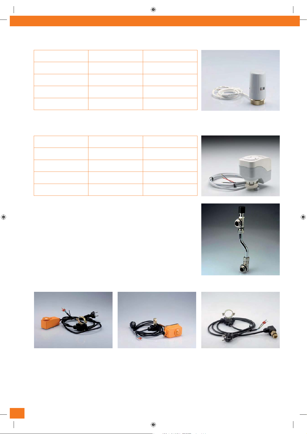
a. with fixed-point adjustment using a thermostatic head with immersion probe and adjustable temperature (30°C - 50°C)
b. with adjustment of the delivery temperature in relation to thermal load variations. The System can be equipped with 24 VAC
axial movement motors (Article SRV 24) with pilot voltage of 0-10 V or with a 24 VAC 0-10V electro-thermal motor (Article TE
3061), both of which can be piloted through the DHCC100 or the WLM2-1FS electronic adjustment control units with offsets
for external temperature.
UNIMIX ist ein innovatives System, das sich gegenüber anderen Regelsystemen für Fußbodenheizungen dadurch auszeichnet, dass es
zunächst die Temperatur des vom Heizkessel gelieferten Wassers auf einen günstigen Wert bringt, der dann im Sekundärkreis (Heiz-
platten) weiter verstellbar ist.
UNIMIX ist modular aufgebaut und kann auf einfache Weise direkt an unseren Verteilern für Heizplattenanlagen angeschlossen werden.
Bei Verwendung einer 130-mm Umlaufpumpe ist die Montage auf den Halterungen von 200 mm Länge möglich, während 180-mm
Umlaufpumpen die Verwendung 250 mm langer Halterungen (Art. AC 611) erfordern.
Das System kann mittels unserer abgewinkelten Kugelhahnen AC 655 sowohl von unten als auch von der Seite versorgt werden, was
dem Montagepersonal jede gewünschte Einbaukonfiguration ermöglicht.
Die Vielseitigkeit dieser Regelgruppe erweist sich insbesondere beim Einsatz mit gemischten Systemen, bei denen ein Hochtemperatur-
kreislauf (Heizkörpersystem) mit einem Kreislauf niedrigerer Temperatur (Heizplatten einer Fußbodenheizung) in Verbindung steht.
Dies ist zum Beispiel oft in Wohnungen der Fall, in denen eine Fußbodenheizung, jedoch auch zusätzliche Heizkörper im Bad (Hand-
tuchwärmer etc.) vorhanden sind. Zur Erstellung eines solchen Systems ist am Eingang des UNIMIX einfach der neue Hochtemperatur-
Versorgungssatz mit Füll- und Ablasshähnen, Vor- und Rücklaufverteilern und Überdruckdifferenzialventil anzuschließen, der in zwei
Versionen verfügbar ist:
1. Hochtemperatursatz mit Mikrometer-Ausgleichventilen und motorisierbarem Absperrventil mit elektrothermischem Kopf
und Ableitungsanschlüssen über M24x1,5-Gewinde oder Eurokonus. Für den Anschluss am Primärkreis sind gerade oder
abgewinkelte Kugelhahnen verfügbar.
2. Einfache Hochtemperaturverteiler mit M24x1,5- oder Eurokonus-Verschraubungen, wobei auch hier für den Anschluss am
Primärkreis gerade oder abgewinkelte Kugelhahnen verfügbar sind.
Das UNIMIX-System kann auf die folgenden zwei Arten betrieben werden:
a. mit Einstellung auf einen festen Sollwert mittels eines Thermostatkopfes mit Tauchsonde, der im Temperaturbereich 30°C -
50°C verstellbar ist,
b. mit Einstellung der Vorlauftemperatur in Einklang mit Änderungen der Wärmebelastung. Das System kann mit 24 V AC Line-
armotoren (Art. SRV 24) mit Steuerspannung 0-10 V oder mit einem elektrothermischen Stellantrieb für 24 V AC 0-10 V (Art.
TE 3061) ausgestattet werden. In beiden Fällen ist eine Steuerung durch die elektronischen Steuermodule DHCC100 oder
WLM2-1FS möglich mit Ausgleich für die Außentemperatur.
IVAR_UNIMIX_E_DE.indd 3 05-11-2008 10:04:10

Absperrventil - stop valve
manuelles Entlüftungsventil - manual air vent valve
automatisches Entlüftungsventil - automatic air vent valve
Ablassventil - drainage valve
Temperaturfühler - temperature sensor
Temperatur und Druckmessung - thermo-manometer
Thermometer - thermometer
Pumpe - pump
Ausgleichsventil - balancing valve
Thermostatisch betriebenes oder motorisierbares 3-Wege-Mischventil
termostatically operated or motorizable 3-ways mixing valve
Sicherheitsthermostat - safety thermostat
Fig. 2a
Fig. 2b
IVAR_UNIMIX_E_DE.indd 4 05-11-2008 10:04:13

Funktionsprinzip
Das Mischsystem Unimix verwaltet einen in Abbildung 2a-2b gezeigten Flüssigkeitskreislauf. Es zeichnet sich durch Vollständigkeit
(alle für die richtige Einstellung und den optimalen Betrieb erforderlichen Ausstattungen sind enthalten), einfache Wartung und sehr
kompaktes Design aus (Gesamtlänge einschließlich Pumpe und Motor: 250 mm; Tiefe: 110 mm) Das heiße Wasser aus dem Heizkessel
erreicht den UNIMIX-Eingang (A) am 3-Wege-Mischventil, das mittels eines Thermostatkopfs auf einen festen Sollwert zwischen 30
und 50°C, oder über Motorantrieb auf veränderliche Weise eingestellt werden kann. Dieses Ventil regelt die Mischung so, dass die
Flüssigkeit am Ausgang (B) mit der (manuell oder elektronisch) eingestellten Temperatur bereitgestellt werden kann. UNIMIX ist so
konstruiert, dass bei voller Last das Mischventil bei direktem Durchgang mit maximaler Öffnung arbeiten kann und somit Druckabfälle
an seinen Köpfen begrenzt: Der Ausgleichs-Bypass mit hohem Kv-Wert (3) gewährleistet bei Bedarf eine erhebliche Rückführung des
von den Heizplatten kommenden Wassers und sichert somit das korrekte Mischen auch beim Einsatz herkömmlicher Hochtemperatur-
Heizkessel.
Das gemischte Wasser wird vom Temperaturfühler kontrolliert und über den Ausgang B zu den Verbrauchern geführt. An Punkt C erfolgt
die Rückleitung von den Heizplatten und das Wasser kann von hier in durch die Stellung des 3-Wege-Ventils und des Ausgleichs-Bypass
(3) bestimmten Mengen in drei Richtungen geleitet werden:
OlZ^\&/Y^gZ`iZGX`[]gjc\ojb=Z^o`ZhhZaVcEjc`i9!
OlZ^\'/GX`[]gjc\ojgYg^iiZcAZ^ijc\YZhB^hX]kZci^ah!
OlZ^\(/GX`[]gjc\ojgB^hX]lVhhZgaZ^ijc\WZgYZc7neVhh(#
Das UNIMIX-System ist auch mit einem Primär-Bypass (2) ausgerüstet um das Heizkesselwasser zurückzuführen. Dieser Bypass ist be-
sonders bei Zentralheizungen mit einem einzigen Heizkessel, der mehrere UNIMIX-Einheiten versorgt, von Nutzen, da er eine hydrauli-
sche Trennung der Flüssigkeitsströme zu den verschiedenen Abnehmern erlaubt und deren Unabhängigkeit sichert sowie gegenseitige
Beeinflussungen der Pumpen der Sekundärkreise ausschließt, oder auch bei Anwendungen, in denen der Heizkessel für den korrekten
Betrieb die Rückführung geringerer Mengen erfordert.
Betriebsbedingungen:
Höchsttemperatur im Primärkreis: 90°C
Maximaler Betriebsdruck: 10 bar
Principle of operating
Unimix is a mixing system involving the hydraulic circuit shown in Figure 2a-2b. The group is distinguished by completeness (all neces-
sary accessories for correct adjustment and optimal operation are included) as well as simple maintenance and very compact overall
dimensions (total length including pump and motor: 250 mm; depth: 110 mm) High temperature water from the boiler reaches UNIMIX
inlet (A) fitted with a 3-way mixer valve that can be controlled by means of a thermostatic head, for fixed-point 30÷50°C adjustment,
or motor-driven for modulated adjustment. This valve regulates mixing to ensure delivery (B) of the set temperature (manually or
electronically). UNIMIX was designed to ensure that the mixer valve can work at full load in maximum opening conditions on the straight
line, thereby limiting the pressure drop at its heads: the high KV balance bypass (3) ensures, when required, important recycling of the
return water from the panels, thereby ensuring correct mixing even if traditional high temperature boilers are used.
The mixed water is controlled by the temperature sensor and sent to utilities through outlet B. Point C is the branch return and from
here water can be branched in three directions and variable capacities over three branches depending on the adjustment position of
the 3-way valve and the balance bypass (3):
WgVcX]&/Y^gZXigZijgcidi]ZWd^aZgVied^ci9
WgVcX]'/gZijgcdci]Zi]^gYa^cZd[i]Zb^mZgkVakZ
WgVcX](/gZijgcdci]Zb^mZYa^cZi]gdj\]i]ZWneVhh(
The UNIMIX system is also equipped with a primary bypass (2) to recirculate boiler fluid. This element is particularly useful with centrali-
sed plant having a single boiler supplying several UNIMIX units, since it allows hydraulic separation of the various utilities, ensuring that
they are independent and avoiding phenomena of reciprocal interference between the pumps on secondary circuits, or in applications
where the boiler requires minor recirculation for correct operation.
Operating conditions:
Maximum temperature in the primary circuit: 90°C
Maximum operating pressure: 10 bar
IVAR_UNIMIX_E_DE.indd 5 05-11-2008 10:04:13

UNIMIX
SYSTEM-KOMPONENTEN - SYSTEM COMPONENTS
Mischbausätze - Mixing kits
Art.-Nr. 500438:
Niedrigtemperatur-UNIMIX-System ohne
Kugelhahnen für den Anschluss am Primärkreislauf
Art.-Nr. 500438S:
Niedrigtemperatur-UNIMIX-System mit
abgewinkelten Kugelhahnen für den seitlichen
Anschluss am Primärkreislauf
Code 500438D:
low temperature UNIMIX system with straight ball
valves for low-level connection to the primary circuit
Code 500438:
low temperature UNIMIX system without ball valves
for connection to the primary circuit
Code 500438S:
low temperature UNIMIX system with angle ball
valves for lateral connection to the primary circuit
Art.-Nr. 500438D:
Niedrigtemperatur-UNIMIX-System mit geraden
Kugelhahnen für den Anschluss am Primärkreislauf
von unten
Die Mischbausätze für niedrige Temperatur werden ohne Pumpe und ohne Verteiler geliefert
Mixing kits are supplied without a pump and without distribution manifolds for low temperature
Verteilerbausätze für hohe Temperatur - High temperature distribution kits
Hochtemperatur-Verteiler für UNIMIX mit
abgewinkelten Kugelhahnen und Thermometern für
den Anschluss am Primärkreislauf von unten
Hochtemperatur-Verteiler für UNIMIX mit geraden
Kugelhahnen und Thermometern für den seitlichen
Anschluss am Primärkreislauf
High temperature manifold for UNIMIX without ball
valves for connection to the primary circuit
Hochtemperatur-Verteiler für UNIMIX ohne
Kugelhahnen für den Anschluss am Primärkreislauf
High temperature manifold for UNIMIX with angle ball
valves and thermometers for low-level connection to
the primary circuit
High temperature manifold for UNIMIX with straight
ball valves and thermometers for lateral connection
to the primary circuit
IVAR_UNIMIX_E_DE.indd 6 05-11-2008 10:04:20

Hochtemperatur-Verteiler für UNIMIX mit doppelter
Mikrometereinstellung auf dem Vorlauf und mit
Absperrventilen auf dem Rücklauf.
Art.-Nr./Code Anschlussverbindungen/Offtakes Kugelhahnen/Ball valves
500783 M 24 x 1.5 ohne / No
500783D M 24 x 1.5 gerade / Straight
500783S M 24 x 1.5 abgewinkelt / Angle
500456 Eurokonus ohne / No
500456D Eurokonus gerade / Straight
500456S Eurokonus abgewinkelt / Angle
Hochtemperatur-Verteiler für UNIMIX mit doppelter
Mikrometereinstellung auf dem Vorlauf und mit
Absperrventilen auf dem Rücklauf.
Abgewinkelte Kugelhahnen für den Anschluss am
Primärkreislauf von unten
Hochtemperatur-Verteiler für UNIMIX mit doppelter
Mikrometereinstellung auf dem Vorlauf und mit
Absperrventilen auf dem Rücklauf. Gerade Kugelhah-
nen für den seitlichen Anschluss am Primärkreislauf
High temperature manifold for UNIMIX with double
micrometric adjustment on delivery and cut-out val-
ves on return
High temperature manifold for UNIMIX with double
micrometric adjustment on delivery and cut-out val-
ves on return. Angle ball valves for low-level connec-
tion to the primary circuit
High temperature manifold for UNIMIX with double
micrometric adjustment on delivery and cut-out val-
ves on return. Straight ball valves for lateral connec-
tion to the primary circuit
Art.-Nr./Code Anschlussverbindungen/Offtakes Kugelhahnen/Ball valves
500635 M 24 x 1.5 ohne / No
500635D M 24 x 1.5 gerade / Straight
5000635S M 24 x 1.5 abgewinkelt / Angle
500586 Eurokonus ohne / No
500586D Eurokonus gerade / Straight
500586S Eurokonus abgewinkelt / Angle
Zubehör - Accessories
Feste Sollwerteinstellung mit Thermostatkopf mit Ferntauchsonde (Art.-Nr. 501175U)
Fixed point adjustment with thermostatic head with remote immersion probe (code 501175U)
Einstellbereich
Adjustment range 30÷50°C
Bereich, in dem sich das thermostatische Element nicht ändert
Thermostatic element inalterability range -15/+60°C
Mit Flüssigkeitsausdehnung arbeitender Thermostat
Liquid expansion thermostat -
Möglichkeit für die Begrenzung und Blockierung der Einstellung
Possibility for limiting and blocking adjustment -
IVAR_UNIMIX_E_DE.indd 7 05-11-2008 10:04:24

TE 3061 elektrothermischer Kopf – Art.-Nr. 500887 mit Steuerung durch Proportionalsignal 0-10 V
TE 3061 electro-thermal head - code 500887 with proportional 0-10 V control
Energieversorgung Power supply 24 V AC 50/60 Hz
Leistungsaufnahme Power consumption 3,3 VA
Hub Stroke 3,5 mm
Rückstellkraft Elastic force 90 N
Öffnungs-/Schließzeit Opening/closing time (3V->8V) 60 s/mm
SRV24 Servo-Linearmotor – Art.-Nr. 501267 mit Steuerung durch Proportionalsignal 0-10 V
SRV24 axial servo-motor - code 501267 with proportional 0-10 V control
Energieversorgung Power supply 24 V AC 50/60 Hz
Leistungsaufnahme Power consumption 2,5 VA
Hub Stroke 2,5 mm
(5,5 mm max)
Kraft Force 100 N
Öffnungs-/Schließzeit Opening/closing time 34 s
Bypass-Differenzialventil mit Anschlüssen für Verteiler AC 666
Einstellbereich: 0,2 - 0,6 bar
Art.-Nr. 500126 für 200-mm Verteiler
Art.-Nr. 500126L für 250-mm Verteiler
Differential bypass valve with terminals for manifold AC 666
Adjustment range: 0.2÷0.6 bar
Code. 500126 for manifolds with centres 200 mm
Code. 500126L for manifolds with centres 250 mm
Vorverdrahtete Sicherheitsthermostate - Pre-wired safety thermostats
Art.-Nr. 580000U:
Sicherheitsthermostat mit vorverdrahtetem
Kontaktfühler
Einstellbereich: 0 - 90°C
Code. 580000U:
safety thermostat with pre-wired contact
Adjustment range: 0÷90°C
Art.-Nr. 580001U:
Sicherheitsthermostat mit vorverdrahteter
Tauchsonde
Einstellbereich: 20 - 90°C
Code. 580001U:
safety thermostat with pre-wired immersion probe
Adjustment range: 20÷90°C
Art.-Nr. 580014U:
Sicherheitsthermostat mit fester Kalibrierung
(60°C), vorverdrahtet
Code. 580014U:
safety thermostat with fixed calibration (60°C)
pre-wired
IVAR_UNIMIX_E_DE.indd 8 05-11-2008 10:04:31

Anschluss am Heizkessel-Primärkreis:
Beispiel A: Nur Fußbodenheizung
Soll nur eine Fußbodenheizung betrieben werden, so kann das UNIMIX-System ohne Hochtempera-
tur-Bausatz verwendet werden. Es wird empfohlen, Kugelhahne mit G¾” Außengewinde am Ein- und
Ausgang des UNIMIX-System anzuschließen, um eventuelle Wartungsarbeiten zu erleichtern. Diese
Hahne (rot und blau) sind in den Bausätzen bereits unter Art.-Nr. 500438S und Art.-Nr. 500438D
enthalten. Es ist sicherzustellen, dass der Vor- und Rücklauf richtig gemäß Abbildung A angeschlos-
sen sind.
Beispiel B: gemischte Heizkörper- und Fußbodenheizungsanlagen + Hochtemperaturheizkörper
Für gemischte Heizungssysteme mit Fußbodenheizung für den allgemeinen Komfort und Heizkör-
per (zum Beispiel für Handtuchwärmer im Badezimmer) muss das UNIMIX-System mit den Hoch-
temperatur-Bausätzen kombiniert werden. In diesem Fall erfolgt der Anschluss an das primäre
Heizkesselsystem direkt durch den Hochtemperatur-Bausatz.
Auch hier empfehlen wir die Verwendung von Kugelhahnen mit einem 1” G-Außengewinde auf der
Vorlauf- und Rücklaufleitung. Die Bausätze 500456S, 500456D, 500586S, 500586D, 500635S,
500635D, 500783S und 500783D werden bereits mit roten und blauen Kugelhahnen geliefert. Die
richtige Anschlussrichtung an den Kesselleitungen gemäß Abbildung B und C ist sicherzustellen.
Connection to the primary boiler circuit:
Example A: only radiant floor heating
If only floor heating plant is involved, the UNIMIX System can be used without high temperature kit.
To ensure correct installation, it is advisable to fit ball valves with a G ¾” male terminal joint on the
input and output of the UNIMIX system in order to facilitate eventual maintenance work. These
Valves (red and blue) are already included in the kits with code 500438S, code 500438D. Make sure
the delivery and return are connected correctly as shown Figure A.
Example B: mixed radiant and flooring heating plant + high temperature radiators
For mixed heating systems, with floor plant for general comfort and radiators or heated towel racks
in bathrooms, the UNIMIX system must also be combined with high temperature kits. In this case,
connection to the primary boiler system is made directly through the high temperature kit. We
again advise using ball valves with a G male terminal joint 1” on delivery and return. Kits 500456S,
500456D, 500586S, 500586D, 500635S, 500635D, 500783S and 500783D are already supplied with
red and blue ball valves. Verify the correct connection direction with the pipes from the boiler as
shown in Figures B and C.
Verbindung des UNIMIX mit Verteilern für niedrige Temperatur (Fußbodenheizung)
Verteiler für Fußbodenheizungen sollten mit der VORLAUFLEITUNG OBEN und der RÜCKLAUFLEITUNG UNTEN positioniert werden, was von den allgemein
von IVAR gelieferten Systemen abweicht. Siehe Abbildungen D und E für weitere Einzelheiten.
Connection of UNIMIX to low temperature distribution manifolds (floor):
floor-type distribution manifolds should be positioned with DELIVERY AT THE TOP and RETURN AT THE BOTTOM: this differs from the systems generally
supplied by IVAR. See images D and E for more details.
A
B
C
D E
OK NO
IVAR_UNIMIX_E_DE.indd 9 05-11-2008 10:04:37

Anschluss der Pumpe
Die Umlaufpumpe (10) des Sekundärkreises muss zwischen zwei drehbaren Ansät-
zen montiert werden, wobei darauf zu achten ist, dass die Pumpe nach oben pumpt
(Abb. F). Es wird auch empfohlen, passende Flachdichtungen einzusetzen, wie sie nor-
malerweise mit der Umlaufpumpe geliefert werden.
Der Elektroanschluss der Pumpe darf nur von qualifiziertem Fachpersonal vorgenom-
men werden.
WICHTIG: Wird eine herkömmliche Pumpe mit fester oder in drei Stufen verstellbarer
Drehzahl verwendet, so wird dringend empfohlen, auf der Sekundärleitung eine etwai-
gen Überdruck ausgleichende Bypassleitung einzubauen. Zum Beispiel kann der Artikel
AC 666 leicht an einer Anschlussstelle des Verteilers angebaut werden.
Die Einbaurichtung des Bypassventils ist besonders zu beachten. Der Bausatz muss so
positioniert werden, dass sich der schwarze Knopf am unten befindlichen Rücklaufver-
teiler befindet, wie dies in Abbildung G gezeigt ist. Bei Verwendung einer elektronisch
gesteuerten Verstellpumpe ist die Montage der Überdruck-Bypassleitung jedoch nicht
erforderlich.
Bei einer 130 mm langen Pumpe müssen die Verteiler auf 200 mm breiten Halterun-
gen und bei Pumpenlängen von 180 mm auf Halterungen einer Breite von 250 mm
befestigt werden.
Connection of the pump:
the secondary circulation pump (10) must be fitted between two rotary nuts, making
sure that the direction of pump thrust is upwards (Fig. F). It is also advisable to fit
suitable flat gaskets that are generally supplied with the circulation pump.
The electrical connection of the pump must exclusively be made by qualified person-
nel.
IMPORTANT: if a traditional fixed speed or three speed pump is used, it is strongly advi-
sed to fit a differential overpressure bypass to the secondary circuit. Article AC 666, for
example, can be easily installed as a terminal on the distribution manifolds. Take great
care as regards the assembly direction of the bypass valve: the kit must be positioned
so that the black knob is on the return manifold (the one at the bottom) as shown in
Figure G. If a variable speed pump with electronic control is used, the overpressure
bypass, on the other hand, does not have to be fitted.
With pump length 130 mm manifolds must be fitted on brackets with centres 200
mm, for pump length 180 mm manifolds must be mounted on brackets with centres
250 mm.
Füllen der Anlage
Zum richtigen Füllen der Anlage ist der Anschluss des Füllsystems am Füll-/Entlee-
rungshahn (8) erforderlich, wobei der Kugelhahn (7b) in offener Stellung verblei-
ben muss. Der Kugelhahn (7a) auf dem Zulauf ist zu schließen und das manuelle
Entlüftungsventil (9) zu öffnen. Die Kappe auf dem automatischen Entlüftungsventil
(5) lockern und dann die Anlage füllen. Sobald aus dem manuellen Entlüftungsventil (9)
Wassertropfen austreten, ist der Füllvorgang abgeschlossen. Diese Maßnahme muss
für jeden Kreislauf getrennt vorgenommen werden.
Filling the plant:
correct filling of the plant requires connecting the filling system to the fill/empty cock
(8), leaving the ball valve in an open position (7b); close the ball valve (7a) on delivery,
open the manual breather (9), slacken the cap on the automatic breather (5) and then
fill the plant. As soon as drops of water emerge from the manual breather (9), filling is
complete. This operation must be performed separately for every circuit.
F
G
IVAR_UNIMIX_E_DE.indd 10 05-11-2008 10:04:40

Montage des Sicherheitsthermostats
IVAR bietet mehrere vorverdrahtete Arten von Sicherheitsthermostaten (siehe den Abschnitt
Zubehör), an denen jeweils eine Verbindungsmöglichkeit zum UNIMIX-System vorgesehen ist.
Die richtige Positionierung der Vorrichtung ist in Abbildung H gezeigt und sieht eine Befesti-
gung der Verbindung am Achtkant links neben dem blauen Kugelhahn der Rücklaufleitung des
Niedertemperaturverteilers vor.
Der Sicherheitsthermostat seinerseits ist bei Verwendung eines Kontaktfühlers, Art.-Nr.
580000U (Abb. I) auf dem Vorlaufverteiler zu positionieren, jedoch bei Verwendung einer
Tauchsonde, Art.-Nr. 580001U oder bei fester Kalibrierung, Art.-Nr. 580014U an der Stelle
des Stopfens (Abb. L). Das Pumpen-Anschlusskabel darf nur von ausgebildetem Fachpersonal
angebracht werden.
Fitting the safety thermostat:
IVAR offers several pre-wired types of safety thermostat (see accessories section) each of
which envisages a link for fixing to the UNIMIX system. Correct positioning of the device is
shown in Figure H and envisages anchorage of the link to the octagonal nut on the left of the
blue ball valve on the return of the low temperature manifolds.
The safety thermostat, on the other hand, should be positioned on the delivery manifold, if
contact type, code 580000U (Fig. I) or in place of the plug if immersion type, code 580001U
or fixed calibration type, code 580014U (Fig. L). The pump connection cable must exclusively
be fitted by specialist personnel.
Regelungsarten
Das UNIMIX-System ermöglicht die Regelung auf einen festen Sollwert mittels des Thermo-
statkopfes und eine modulierte Regelung bei Verwendung eines Antriebs. Der Thermostat-
kopf oder elektrothermische (oder elektromechanische) Antrieb ist wie in Abbildung M gezeigt
auf dem 3-Wege-Kolbenmischventil (1) zu montieren. Hierzu muss die weiße Schutzkappe
entfernt und an ihrer Stelle der Kopf oder Antrieb angeschlossen werden. Die Muffe ist hierbei
nur leicht festzuziehen. Bei Regelung auf einen festen Sollwert ist die Tauchsonde des Kopfes
wie in Abbildung N gezeigt im speziellen Messfühlerhalter (4) zu positionieren. Bei modulier-
ter Regelung kann der mit der Verstellvorrichtung verbundene Zulauf-Messfühler im Schacht
(15, Abb. L) angebaut werden, wenn es sich um eine Tauchsonde handelt, oder bei einem
Kontaktfühler mittels eines Klemmbands am Verteiler der Zuleitung gesichert werden.
Type of adjustment:
The UNIMIX System allows fixed point adjustment through a thermostatic head and modula-
ting adjustment through a motor. The thermostatic head or electro-thermic (or electro-me-
chanical) motor should be positioned at the 3-way piston type mixer valve (1), shown in Fig.M.
It is therefore necessary to remove the white protection cap and position the head or the
motor, tightening the lock ring moderately. For fixed point adjustment the head immersion
probe should be positioned in the specific probe-holder (4), shown in Fig. N. In the event of
modulating adjustment, it is possible to fit the delivery probe connected to the conditioning
adjuster in the pit (15, Fig. L) for an immersion probe or secure it to the delivery manifold by
means of band for contact type sensor.
15
H
I
L
MN
Messfühlerhalterung
Probe-holder
IVAR_UNIMIX_E_DE.indd 11 05-11-2008 10:04:46

Bypass Hochtemperatur-Primärleitung (2):
Der Bypass der Hochtemperatur-Primärleitung (2) dient zur Rückführung des heißen Wassers zum Kesselrücklauf. Auf diese Weise ist
die Temperatur des zurücklaufenden Wassers höher.
Es wird empfohlen, den Bypass zu öffnen, wenn Kessel den Rücklauf für den optimalen Betrieb notwendig machen und wenn mehrere
UNIMIX-Einheiten im selben Gebäude installiert sind und von einem einzelnen Kessel versorgt werden.
Primary High Temperature Bypass (2):
the primary high temperature bypass (2) is used to recirculate hot water on the boiler return; in this way, the return water has a higher
temperature. It is advised to open the bypass if boilers require recirculation for optimal operation and if several UNIMIX units are instal-
led in the same building and powered by a single boiler.
Regelung der Anlage:
Die richtige Regelung der Anlage wird nachfolgend in Grafiken in Form von Durchflussmengen und Druckabfällen an den verschiedenen
Komponenten des UNIMIX-Systems angezeigt. In allen Fällen ist es möglich, die maximale Kalibrierung wie folgt durchzuführen:
9Vh("LZ\Z"B^hX]kZci^akdaahi~cY^\\Z[[cZiaVhhZc!d]cZYZcI]ZgbdhiVi`de[dYZgYZcBdidgojbdci^ZgZc#
9^ZhZ`jcY~gZ6jh\aZ^X]h"7neVhhaZ^ijc\(kdaahi~cY^\[[cZc#
H^X]ZghiZaaZc!YVhhYVhLVhhZg^b=Z^o`ZhhZaYZcIZbeZgVijghdaalZgiZggZ^X]i]VijcYYVccLVhhZgYjgX]Y^Z6caV\ZaVj[Zc
lassen. Dabei die Vorlauftemperatur mit dem Temperaturmessfühler (5) prüfen. Es können drei Fälle eintreten:
Beispiel A) Die Vorlauftemperatur entspricht dem projektierten Einstellwert: In diesem Fall ist die Kalibrierung beendet.
Beispiel B) Die Vorlauftemperatur liegt unter der projektierten Einstellwert: In diesem Fall ist der Bypass (3) im Sekundär-
kreis langsam zu schließen ist, bis sich die Vorlauftemperatur auf den projektierten Einstellwert stabilisiert.
Beispiel C) Die Vorlauftemperatur ist höher als der projektierte Einstellwert: In diesem Fall ist die Temperatureinstellung
des Heizkessels, wenn möglich, zu senken und die Kalibrierung zu wiederholen oder der Thermostatkopf oder
Motor zu montieren. Letztere Vorrichtungen versuchen die Solltemperatur durch Verstellen des Mischventils zu
erreichen.
Adjustment of the plant:
correct adjustment of the plant is outlined below through graphs illustrating capacity and losses of load involving the components in
the UNIMIX system. It is in any case possible to set maximum calibration as follows:
aZVkZi]Z("lVnb^mZgkVakZ[jaandeZcl^i]dji[^ii^c\i]Zi]ZgbdhiVi^X]ZVYdgi]Zbdidg
XdbeaZiZandeZci]ZhZXdcYVgnWVaVcXZWneVhh(
kZg^[ni]ViWd^aZglViZg]VhgZVX]ZYi]ZhZiiZbeZgVijgZVcYi]ZcX^gXjaViZlViZgi]gdj\]i]ZeaVci!X]ZX`^c\i]ZYZa^kZgn
temperature value through the temperature-pressure gauge (5). Three cases may arise:
Example A) the delivery temperature matches the project setting: in this case, calibration is complete
Example B) delivery temperature is less than the project setting: in this case, begin slowly closing the secondary balance
bypass (3) until the delivery temperature stabilised at the project setting
Example C) delivery temperature is higher than the project setting: in this case, where possible, reduce the temperature
set for the boiler and resume the calibration process or fit the thermostatic head or motor: these devices act
on the mixer valve in order to reach the set temperature.
P
IVAR_UNIMIX_E_DE.indd 12 05-11-2008 10:04:47

Wärmeabgabe unter Bedingungen maximaler Belastung
Zur Unterstützung des Installationspersonals und zur Vermeidung komplizierter Berechnungen liefern wir in den nachstehenden Tabel-
len einige Beispiele, die auf einfache Weise zur Bestimmung der unter Bedingungen maximaler Belastung erforderlichen Wärmeabgabe
verwendet werden können.
Dabei werden zwei Situationen geschildert, bei denen der Druckabfall am Mischventil und am Bypassventil auf der Sekundärleitung
100 mbar und 150 mbar betragen. Durch Hinzufügung dieser Werte zu Druckverlusten des ungünstigeren Kreises kann die Mindest-
förderhöhe der Umlaufpumpe berechnet werden. Zur Wahl der am besten geeigneten Pumpe muss die an die Verbraucher zu liefernde
Fördermenge berücksichtigt werden, die auf einfache Weise mit folgender Formel berechnet werden kann:
RM
p
TT
E
Q
860
mit Ep in kW und Q in l/h.
mit:
Tc = Kesseltemperatur (°C)
Tr = Rücklauftemperatur von Verbrauchern (°C)
Tm = Temperatur des den Verbrauchern zugeführten Mischwassers (°C)
Ep = Wärmeabgabe bei maximaler Belastung (kW)
Bypass = Anzahl der Umdrehungen zum Öffnen des Bypass auf der Sekundärleitung (Mikrometerschraube)
Thermal output in maximum load conditions
To help installation personnel and avoid complicated calculations, we provide in the tables below some examples which can be easily
used to identify the thermal output required in maximum load conditions.
Two different situations are outlined where the drop in pressure on the mixer valve and the secondary balance bypass are respectively
100 mbar and 150 mbar. By adding this value to the losses of load in the worst-case loop, it is possible to calculate the minimum head
of the circulation pump. In order to select the most appropriate pump, add the capacity head and the total capacity to utilities. The
capacity value is easily calculated using the following formula:
RM
p
TT
E
Q
860
with Ep in kW and Q in l/h.
Key:
Tc = boiler temperature (°C)
Tr = return temperature from utilities (°C)
Tm = temperature of the mixed water sent to utilities (°C)
Ep = thermal output in maximum load conditions (kW)
Bypass = opening turns number of secondary bypass. Turns number refers to the micrometric adjustment dowel
∆p = 100 mbar
TC(°C) TR(°C) TM(°C) Ep(kW) Bypass TC(°C) TR(°C) TM(°C) Ep(kW) Bypass
40 30 35 13 4 40 30 38 13 1
45 30 35
16 Aperto
Open
45 30 38 20 3 ¼
50 30 35 50 30 38
27 Aperto
Open
55 30 35 55 30 38
60 30 35 60 30 38
65 30 35 65 30 38
70 30 35 70 30 38
75 30 35 75 30 38
40 30 36 13 2 ¼ 40 30 39 13 ½
45 30 36
20 Aperto
Open
45 30 39 20 2 ¼
50 30 36 50 30 39 27 6 ¼
55 30 36 55 30 39
30 Aperto
Open
60 30 36 60 30 39
65 30 36 65 30 39
70 30 36 70 30 39
75 30 36 75 30 39
40 30 37 13 1 ½ 40 30 40 13 Chiuso/Closed
45 30 37 20 5 ½ 45 30 40 20 1 ¾
50 30 37
23 Aperto
Open
50 30 40 27 4
55 30 37 55 30 40
33 Aperto
Open
60 30 37 60 30 40
65 30 37 65 30 40
70 30 37 70 30 40
75 30 37 75 30 40
IVAR_UNIMIX_E_DE.indd 13 05-11-2008 10:04:47

TC(°C) TR(°C) TM(°C) Ep(kW) Bypass TC(°C) TR(°C) TM(°C) Ep(kW) Bypass
40 30 35 16 4 40 30 38 16 1
45 30 35
20 Aperto
Open
45 30 38 25 3 ¼
50 30 35 50 30 38
33 Aperto
Open
55 30 35 55 30 38
60 30 35 60 30 38
65 30 35 65 30 38
70 30 35 70 30 38
75 30 35 75 30 38
40 30 36 16 2 ¼ 40 30 39 16 ½
45 30 36
25 Aperto
Open
45 30 39 25 2 ¼
50 30 36 50 30 39 33 6 ¼
55 30 36 55 30 39
37 Aperto
Open
60 30 36 60 30 39
65 30 36 65 30 39
70 30 36 70 30 39
75 30 36 75 30 39
40 30 37 16 1 ½ 40 30 40 16 Chiuso/Closed
45 30 37 25 5 ½ 45 30 40 25 1 ¾
50 30 37
28 Aperto
Open
50 30 40 33 4
55 30 37 55 30 40
41 Aperto
Open
60 30 37 60 30 40
65 30 37 65 30 40
70 30 37 70 30 40
75 30 37 75 30 40
Angaben für Anlagenplaner
Dieser Abschnitt enthält komplette Grafiken für die Komponenten des UNIMIX-Systems (Mischventil und Ausgleichs-Bypass auf der
Sekundärleitung), die bei der Planung von Anlagen helfen sollen, die Systemleistungen genau zu berechnen und das System richtig zu
kalibrieren.
Einstellung des Ausgleichs-Bypass auf der Sekundärleitung:
Der Ausgleichs-Bypass auf der Sekundärleitung ist mit einer doppelten Mikrometereinstellung mit Positionsspeicher (für den Fall vor-
übergehender Abschaltung) versehen. Zur richtigen Einstellung folgendermaßen vorgehen:
1. Mit einem Schraubenzieher den in der Sechskantöffnung befindlichen Verriegelungsstift herausdrehen und entfernen.
2. Mit einem 5-mm Stiftschlüssel die große Einstellschraube festdrehen (Abb. Q1)
3. Den Verriegelungsstift wieder voll eindrehen. Die Einstellposition mit einem “x” markieren (Abb. Q2).
4. Den Schraubenzieher auf das “x” ausrichten und dann einige Umdrehungen öffnen (Abb. Q3) wie in der Grafik ∆p-Q des
Sekundär-Bypass ersichtlich. (ACHTUNG: Die Anzahl der Umdrehungen entspricht denjenigen des Verriegelungsstiftes!).
5. Dann die große Schraube bis zum Anschlag losschrauben (Abb. Q4). Die Voreinstellung ist nun durchgeführt und ändert sich
nicht, auch nicht nach wiederholtem Öffnen/Schließen mit dem Stiftschlüssel.
Indications for plant designers:
this section includes complete diagrams of the components in the UNIMIX system (mixer valve and secondary balance bypass) in order
to help designers make accurate calculations of system performances and correct calibration of the system.
Adjustment of the secondary balance bypass:
the secondary balance bypass is fitted with dual creep adjustment with position memory in the event of temporary closure. for correct
adjustment and balancing of the circuit, refer to the following procedure:
1. Use a screwdriver to back off and remove the lock dowel with notch inside the hexagonal hole
2. close the large adjustment screw using an Allen wrench of 5 mm (Fig. Q1)
3. snugly re-tighten the lock dowel with notch. Indicate the adjustment landmark with “x” (fig. Q2).
4. Align the screwdriver with “x”. Then open by a few turns (fig. Q3) with reference to diagram ∆p-Q detailing the secondary
bypass (CAUTION: the number of turns refers to the number of turns of the creep adjustment dowel!).
5. Then open the large screw to the locator limit (fig. Q4). Pre-adjustment has now been made and will not change even following
repeated opening/closing using the Allen wrench.
∆p = 150 mbar
IVAR_UNIMIX_E_DE.indd 14 05-11-2008 10:04:47

Sekundär-Bypass – Secondary Bypass Mischventil – Mixing Valve
Wahl des Wandschranks:
IVAR verfügt über ein umfangreiches Angebot von Wandschränken zur Montage des UNIMIX-Systems. Diese bieten eine zwischen 110
und 160 mm verstellbare Tiefe, eine zwischen 690 und 790 mm verstellbare Höhe und eine den Artikelnummern in nachstehenden
Tabellen entsprechende Breite. Nachstehend sind empfohlene Abmessungen für Wandschränke entsprechend der Anzahl von Abzwei-
gungen an den Verteilern einer Fußbodenheizung angegeben. Um die Abmessungen der Schränke möglichst klein zu halten, wird
Folgendes vorgeschlagen (jedoch können Installateure andere Lösungsmöglichkeiten nutzen, solange diese den ordnungsgemäßen
Betrieb des Systems nicht beeinträchtigen):
Regelung auf festen Sollwert (TAB. A): Es wird empfohlen, auf der Rücklaufleitung elektrothermische Ein-Aus-Köpfe mit vier Leitungen
und einer 230 V AC-Energieversorgung (Art.-Nr. 500808) zu installieren. Diese Vorrichtungen haben einen Hilfskontakt zur Abschaltung
der Umlaufpumpe. Sind sie alle parallel geschaltet, so schalten sie die Pumpe ab, wenn alle Bereiche zufrieden stellend versorgt wer-
den. An ihrer Stelle können auch elektrothermische Köpfe für 24 V AC mit zwei Leitern (Art.-Nr. 501524) mit einem „Wiring-Centre“
ZC 100 (Art.-Nr. 580004) verwendet werden, die bei einer Schließung aller Bereiche die Pumpe abschalten. Die Elektroanschlüsse der
Köpfe müssen von ausgebildetem Fachpersonal vorgenommen werden. Weitere Informationen sind in der mit den Köpfen gelieferten
Anleitung enthalten.
Modulierte Regelung (TAB. B): Zur Reduzierung der Gesamtabmessungen wird empfohlen, die Bedienelemente für die Klimaregelung
vertikal zu positionieren, um die Gesamtmaße zu reduzieren.
In diesem Fall sind elektrothermische Köpfe zu den Verteilern der Rückleitung mit zwei Leitungen für die Energieversorgung mit 230 V
AC auszustatten. Die Zustimmung zum Abschalten der Sekundärpumpe wird direkt vom Bedienfeld gegeben, an dem die Köpfe ange-
schlossen sind. Weitere Informationen befinden sich in der Anleitung der Klimaregeleinheit.
Q1
Q2
Q3
Q4
IVAR_UNIMIX_E_DE.indd 15 05-11-2008 10:04:50

Selecting the wall box:
IVAR offers a broad range of wall boxes for mounting the UNIMIX system. These boxes offer adjustable depth of 110 mm- 160 mm, an
adjustable height of 690 a 790 mm and width that varies in relation to the article code as listed in the following tables
Recommended dimensions for wall boxes are given below in relation to the number of branches on the floor type distribution manifolds.
In order to minimise overall box dimensions, the following outline suggestions are provided (yet installation experts may adopt different
solutions provided that they do not compromise correct operation of the system):
fixed point adjustment (TAB. A): on the return line, it is advised to fit on-off electro-thermal heads with four leads and 230 VAC power
supply (code. 500808). These devices have an auxiliary contact to switch off the circulation pump and if they are all connected in parallel
they switch off the pump if supplies to all areas are satisfactory. It is alternatively possible to use 24 VAC electro-thermal heads with two
leads (code. 501524) with wiring centre ZC 100 (code 580004) that switch off the pump in the event of closing of all zones. Electrical
wiring for the heads must be performed by qualified personnel. For more information, refer directly to the instruction booklet included
in the packaging of the heads.
modulating adjustment (TAB. B): it is advised to fit the conditioning adjustment control units in a vertical position to reduce overall
dimensions. In this case, fit electro-thermal heads to the return manifolds with two leads with power supply 230 VAC: consent to switch
off the secondary pump is given directly by the control panel to which the heads are connected. For more information, refer to the
conditioning control unit manual.
TAB. A
TAB. B
Bei Verwendung der Hochtemperatur-Bausätze ändern sich die Abmessungen des Schrankes nicht.
The use or otherwise of the high temperature kit does not modify the dimensions of the box
Hinweis: Für ausführlichere technische Informationen setzen Sie sich bitte direkt mit dem
Beistandsdienst von IVAR SPA in Verbindung: assistenzatecnica@ivar.it
N.B.: For more technical information, directly contact the technical assistance service of IVAR SPA:
assistenzatecnica@ivar.it
Anzahl der Ausgänge
Number of outputs Schrankbreite
Box width
Art.-Nr.
Code
Hohe Temp.
High Temp.
Niedrige Temp.
Low Temp.
33 680 mm 540032
34
35
830 mm 54003336
37
38
1030 mm 540034
39
310
311
3121130 mm 540035
313
Anzahl der Ausgänge
Number of outputs Schrankbreite
Box width
Art.-Nr.
Code
Hohe Temp.
High Temp.
Niedrige Temp.
Low Temp.
33
1030 mm 540034
34
35
36
37
381130 mm 540035
39
310
1330 mm 540036
311
312
313
IVAR_UNIMIX_E_DE.indd 16 05-11-2008 10:04:51

IVAR_UNIMIX_E_DE.indd 17 05-11-2008 10:04:53

IVAR_UNIMIX_E_DE.indd 18 05-11-2008 10:04:57

IVAR_UNIMIX_E_DE.indd 19 05-11-2008 10:04:58
Table of contents