J.R. Clancy SC5300 User manual

SC5300 Console User Guide


SceneControl®5000 HARDWARE
Questions/comments regarding this document should be addressed to J.R. ClanCy InC.
This document contains proprietary and condential information of J.R. ClanCy InC. and is protected by
copyright law. The contents of this document may not be disclosed to third parties, translated, copied, or
duplicated in any form, in whole or in part, without the express written permission of J.R. ClanCy InC.
J.R. ClanCy InC. reserves the right to change the information contained in this document without notice.
All product names shown are trademarks or registered trademarks of their respective owners.
For latest revision notes and updates check the Readme.txt le contained on your Raynok CD.
SC5300 Console User Guide
P/N: 5012-00
Version 1.00
June 2014
Copyright © 2001–2014 by J.R. ClanCy InC.
1
J.R. ClanCy InC.
7041 Interstate Island Road
Syracuse NY 13209
Domestic Toll Free: 800 836 1885
International: 001 315 451 3440
24 Hour: 315 451 3440
Fax: 315 451 1766
General Inquiries
Software/Controls Inquiries

SceneControl®5000 HARDWARE
2

SceneControl®5000 HARDWARE
SceneControl®5000 HARDWARE 3
The J.R. Clancy SC5300 Console is the hardware interface to the Raynok Software. The
operator can, with minimal use of the touch screen and/or keyboard, send commands to the
software to execute GO, STOP, Manual and all other executable commands from the user program-
mable macro buttons.
The J.R. Clancy SC5300 Console also has the Operator’s E-stop, E-stop Reset, E-stop Reset
Lockout controls and manual control joystick. The SC5300 macro buttons interface is all done right on
the main touch screen. The SC5300 computer and monitor power is supplied from the SC5300 Power
Distribution, described later in the manual.
Review the following diagrams on the next few pages and familiarize yourself with the J.R. Clancy
SC5300 Console buttons, input/output ports, and features.
SC5300 Console User Guide

SceneControl®5000 HARDWARE
4
SC5300 Console List of Parts
Review the diagrams below to familiarize yourself with the SC5300 Console operator buttons and
physical features.
12911
SC5300 Console ISOMETRIC View Layout
15 1613 17
10
18
SC5300 Console Helm View Layout
3 4 5 6
7 8
12 14

SceneControl®5000 HARDWARE
5
1 – Hold to Run
- The HTR operator enables and inhibits all axes from motion. Press the HTR to enable all axes; release the HTR to
inhibit all axes. The lights will illuminate BLUE when it is held down for the amount of time determined by the Raynok
Software. The lights will be RED when the system is in E-STOP and ORANGE when the system is in a standby state.
2 - Console Helm
- Them main tactile buttons of the SC5300 Console are found here. Refer to the next several lines for detailed information
on the buttons.
3 - Reset Axis
- Press this button to reset the axis that is currently selected in the Raynok Software
4 – Manual Cue
- Used to toggle the Raynok Software from the pre-programmed show cues to the Manual Cue Mode so that the
operator can set up a temporary cue.
5 – Previous Cue
- Used to return the Raynok Software to select the previous show cue for execution.
6 – Next Cue
- Used to advance the Raynok Software to select the next show cue for execution.
7 – Stop
- Used to send the STOP command through the Raynok Software
- the STOP button is illuminated RED.
8 – GO
- Used to send the GO command through the Raynok Software
- The GO button is illuminated GREEN.
9 - Console Screen
- The main visual display for the Raynok Software. See the Raynok SoftwarE GUIDE for further instructions on
running the software.
10 – E-Stop Reset
- Used to reset the Emergency Stop System in conjunction with the E-Stop Reset Lockout Switch.
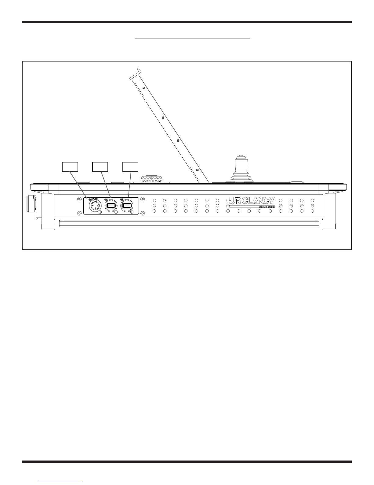
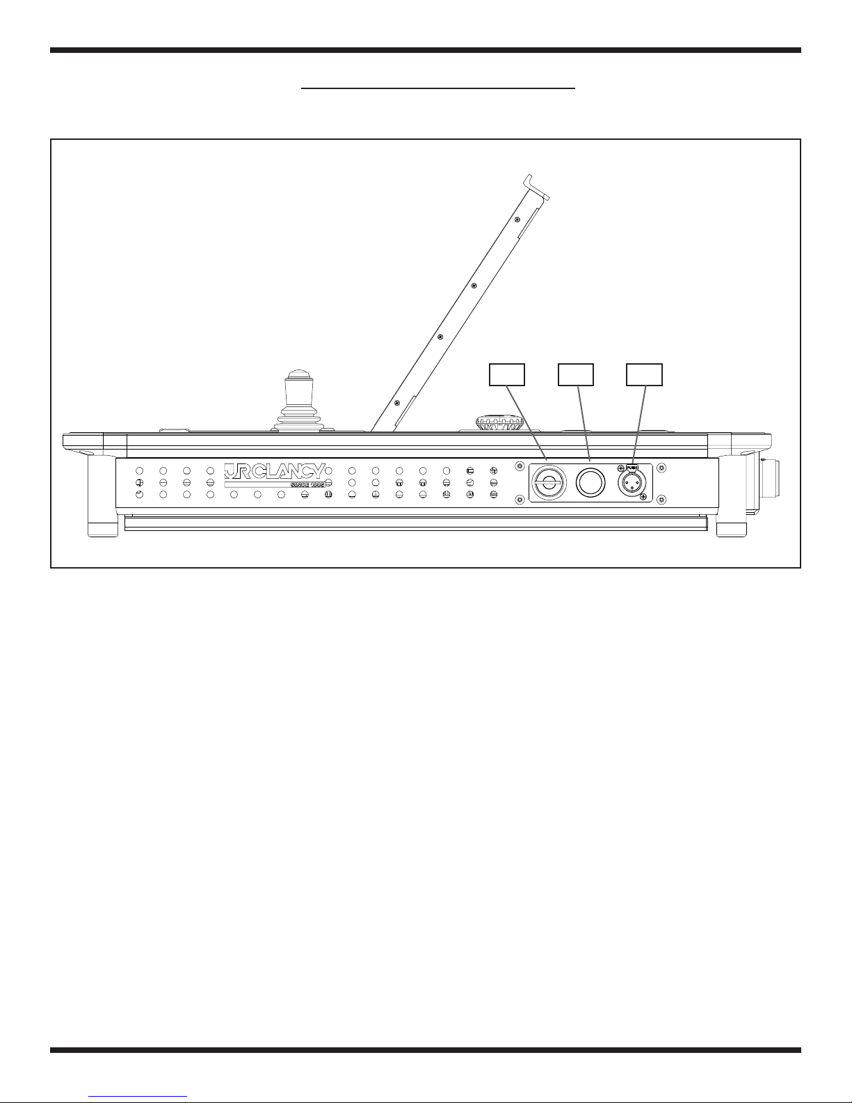
11 - Light Dimming Switch
- This switch adjusts the dimming of the LittlLite that is currently connected to either of the XLR ports on the Left and Right
side of the Console. Functions for dimming are as follows:
- Hold the button down to dim the light slowly between the ON and OFF positions.
- Press the button to toggle the light between ON and OFF.
12 - Main PC ON/OFF
- Turns the main PC inside the console ON or OFF. Hold the button down for 4 seconds to turn the computer off, and hold it
for 1 second to reset
13 - Keyboard
The main keyboard of the computer inside the console. Use this as you would any regular PC keyboard. It is recommended
to push the keyboard tray in until it locks in when running the Console in Show Mode.
14 – USB Port
- Plug any USB device into this, such as a memory card stick, external hard drive, or a mouse
15 - LED Legs
- The legs will illuminate depending on the state of the system. See (1) for further description of the various system states.
16 – Joystick
- use the joystick to manually jog axes. Press the button on the top of the joystick to enable the jog function on selected
axes.
17 – Emergency Stop Button
- Used to Stop the entire system in the case of an emergency.
18 – E-Stop Reset Lockout
- Locks out the local E-stop Reset button so that the resetting of the Emergency Stop System can be properly managed.
turns Off and On the E-stop System and resets the system in conjunction with the reset button.

SceneControl®5000 HARDWARE
6
1 – Emergency Stop I/O
- Connects the Emergency Stop, E-stop Reset Lockout key and the E-stop Reset buttons to the main
Emergency Stop System.
2 - USB Port
- Attach any USB-based device to this port. May or may not be available depending on venue.
3 – MAIN PC Power Inlet
- Plug the cable labeled ‘Main PC Power’ into this socket from the Console Power Distribution.
4 – HDMI port
- Connect an extra monitor to this port (clone view)
5 – NET A FIELD MAIN 10 Base-T port
- Connects the SC5300 Console to the Network Uplink.
6 - NET A FIELD Spare
- Do not connect this unless the rst link has stopped operating
7 – Rear LED Indicators
- Show various states of the PC and the control system as described below
8 – PC ON
- The PC is turned on.
9 - PC HD
- The PC hard drive is being accessed
10 - E-STOP +24V
- The E-Stop System is connected and bringing 24V to the E-STOP Reset, E-STOP BUTTON, and
Keyswitch
11 - HELM Heartbeat
- Indicates that the HELM PCB is functioning by ashing ON and OFF every 1 second.
12- MAIN +12V
- Indicates that there is 12 Volts running to the PC
SC5300 Console Rear View Layout
1 2 3 4 5 6 7
89
10 11 12
REAR LEDs DETAIL

SceneControl®5000 HARDWARE
SceneControl®5000 HARDWARE 7
1 – Light Power 3-PIN XLR
- LittleLite +12VDC power source outlet
2 – USB
- Plug any USB device into this, such as a memory card stick, external hard drive, or a mouse
3 – USB
- Plug any USB device into this, such as a memory card stick, external hard drive, or a mouse
123
SC5300 Console Left View Layout

SceneControl®5000 HARDWARE
8
1 – E-Stop Reset Lockout
- Locks out the local E-stop Reset button so that the resetting of the Emergency Stop System can be
properly managed. turns Off and On the E-stop System and resets the system in conjunction with
the reset button.
2 – Console Power Switch
- Turns the SC5300 Console HELM on and off. The switch will stay depressed (latched).
3 – Light Power 3-PIN XLR
- LittleLite +12VDC power source outlet
NOTE:
The SC5300 Console can be turned OFF and the E-Stop system will still function
properly.
SC5000 Console Right View Layout
123

SceneControl®5000 HARDWARE
SceneControl®5000 HARDWARE 9
(This page is blank)

SceneControl®5000 HARDWARE
10
The SceneControl Power Distribution is the main source of power for the SC5300 Console.
Familiarize yourself with the diagram below and follow safe operating procedures when connecting
any cables to their inlets/outlets. Note: The diagram below may not be an exact representation of
the PD, but all the items are identical and functionality remains the same.
Front View
SceneControl®Power Distribution
1234
Rear View
5679
810 11

SceneControl®5000 HARDWARE
11
1 - FAN VENTILATION
- Ensure this vent is not blocked, as the Power Supplies in the unit need sufcient ventila-
tion in order to not overheat
2 - MAIN 12VDC INDICATOR / FUSE
- Main and Backup (if Applicable) PC power fuse and power indicator
3 - SECONDARY 12VDC INDICATOR / FUSE
- Touch Screen PC, KVM, and NET HUB power fuse and power indicator
4 - Power Button
- Push this button to turn the power on for the 12V Power Supplies. The button will be lit
when the power is on
5 - E-STOP LINK IN PORT
- connect the main emergency stop system through this port
6 - E-STOP LINK OUT PORT
- Used to connect the SceneControl Console to the Emergency Stop System. Connect this
port to the rear of the SceneControl Unit.
7 - MAIN PC POWER OUTLET
- Used to supply power to the main PC(s) and devices within the Console.
8 - POWER INLET
- Connect the Back-UPS unit to this port to provide the unit with AC Power.
9 - MONITOR POWER OUTLET
- used to supply power to the monitors (NOT USED FOR SC5300).
10 - NET-1
- Network 1 pass through ports
11 - NET-2
- Network 2 pass through ports

SceneControl®5000 HARDWARE
12
Connecting the SC5300 Console To the Main System
1. BEFORE USING YOUR SC5300 Console BE SURE YOU UNDERSTAND AND
FOLLOW ALL BASIC SAFETY GUIDELINES AS LAID OUT BY YOUR SYSTEM
ADMINISTRATOR.
2. Ensure that the E-stop button on the SC5300 Console is pushed in.
3. Press and pull out the local E-stop button on the E-Stop Master Controller to disable
the system.
4. Connect the Console Power Distribution (PD) to the CONSOLE-1 Port on the
E-Stop Master Controller using the E-Stop/Data Extention Cable.
5. Pull out the Emergency Stop button on the SC5300 Console.
6. Turn and hold the Emergency Stop Reset Lockout key and press the E-stop Reset
button.
7. Release the Emergency Stop Reset Lockout key and E-stop Reset button.
8. The Main Emergency Stop System should now be reset.
9. Press the Emergency Stop button.
10. The Emergency Stop System should now be disabled.
11. Turn on the power switch for the SC5300 Console Helm using the switch on the
right hand side of the console.
12. Your SC5300 Console will now perform a self-diagnostic test, lamp test and boot
up.
13. You are now ready to conrm communications and use your SC5300 Console.
14. Once you have conrmed communications, reset the Main Emergency Stop System
by following items 5, 6 and 7 above.
IMPORTANT NOTE OF CAUTION!!!
Before you operate any equipment connected to your system it is imperative that you test
your Emergency Stop and E-stop Reset buttons. Failure to do so could result in a serious
injury or even death should this equipment not be ready to function when needed.

SceneControl®5000 HARDWARE
13
Console Startup & Shutdown Procedure
Startup
Turn Main Computer “ON”
Wait for computer to boot up
Start Raynok and Login
Open the Show File needed for the venue.
Setup Menu - “GO ONLINE”
Reset E-Stop System - Turn the key switch to the right, hold and press “RESET”.
Setup menu - “EXIT E-STOP RESET MODE” (If Applicable)
Turn Console “ON” - Power Switch on Right
Shutdown
E-Stop system - Push in and pull out E-Stop Button
Setup menu - “GO OFFLINE”
“YES” to save current positions
File Menu - “EXIT”
Save Changes - “YES”
Computer Start menu - “SHUT DOWN” (wait until computer totally shuts down)

SceneControl®5000 HARDWARE
14
RAYNOK Basic Procedures
To Move Battens
Reset E-Stop system
Setup Menu - “EXIT E-STOP RESET MODE”
Select batten
Set target by using any of the following
1. Use “INTRIM” macro
2. Use “OUTTRIM” macro
3. Or use “ASK TARGETS” macro
Reset Axis
Press “GO” to initiate movement
Press “STOP” to stop if needed
Press “CLEAR” to deselect all battens
Press “MANUAL CUE” twice to clear targets
Select another batten
And so on….
To Jog Battens
Select batten.
Reset Axis
Press down the button on top of the joystick to start the machine, and move the joystick in desired
direction and to jog the batten

SceneControl®5000 HARDWARE
15
Test and Boot Up of the SC5300 Console
After turning on the power to the SC5300 Console it will perform a lamp test to illustrate to you that
all of the LED indicators are in proper working order. The LEDs will turn on and then off, chase from
left to right, top to bottom and then turn on and off again.
Once this lamp test is complete the SC5300 Console will complete its boot up process and self test
and be ready for use. For details on how to conrm that the unit is communicating with the rest of
the network properly refer to your Raynok software guide.
SC5300 Console Manual Control Joystick
The Manual Control Joystick is available for the operator to use to control individual or non-linked
axis or axis groups for simple jog moves.
Basic Operation
1. BEFORE USING YOUR SC5300 CONSOLE LOCAL MANUAL CONTROL
JOYSTICK, BE SURE YOU UNDERSTAND AND FOLLOW ALL BASIC SAFETY
GUIDELINES AS LAID OUT BY YOUR SYSTEM ADMINISTRATOR.
2. Select an axis by highlighting it on your monitor with your mouse. Refer to your
Raynok Software guide for details on how to do this properly.
3. Allow the joystick to sit in its centre “off” position without the aid of your hand.
4. Press and hold the Joystick Enable button on the top of the joystick.
5. Wait approximately 2 seconds for the drive to produce torque and engage the brake
relays.
6. You should see the status of the selected axis change to Jogging. Refer to your
Raynok Software guide for details on the Status Column display
7. While looking at the machine, scenery or load in motion, gently ease the joystick in
the direction of intended travel.
8. Ease up on the joystick as you approach the intended stopping point.
9. For a quick stop, release the Drive Enable button. (CAUTION: BE certain that a
quick stop will NOT damage attached equipment BEFORE attempting to release the
Drive Enable while in motion)

SceneControl®5000 HARDWARE
16
notes

SceneControl®5000 HARDWARE
17
notes
Table of contents