JetCat P80 User manual

Page 1/39
JetCAT P80
Instruction manual
Ing. Büro CAT
M.Zipperer GmbH
Etzenbach 16
79129 Staufen
Tel.: 07636-78030
Fax: 07636-7208
Internet: www.cat-ing.de

Page 2/39
Table of contents Page
Introduction............................................................................................................................................................3
Safety Precautions ................................................................................................................................................4
The Checklist.........................................................................................................................................................5
Before Running the Turbine .....................................................................................................................5
After Stopping the Turbine........................................................................................................................5
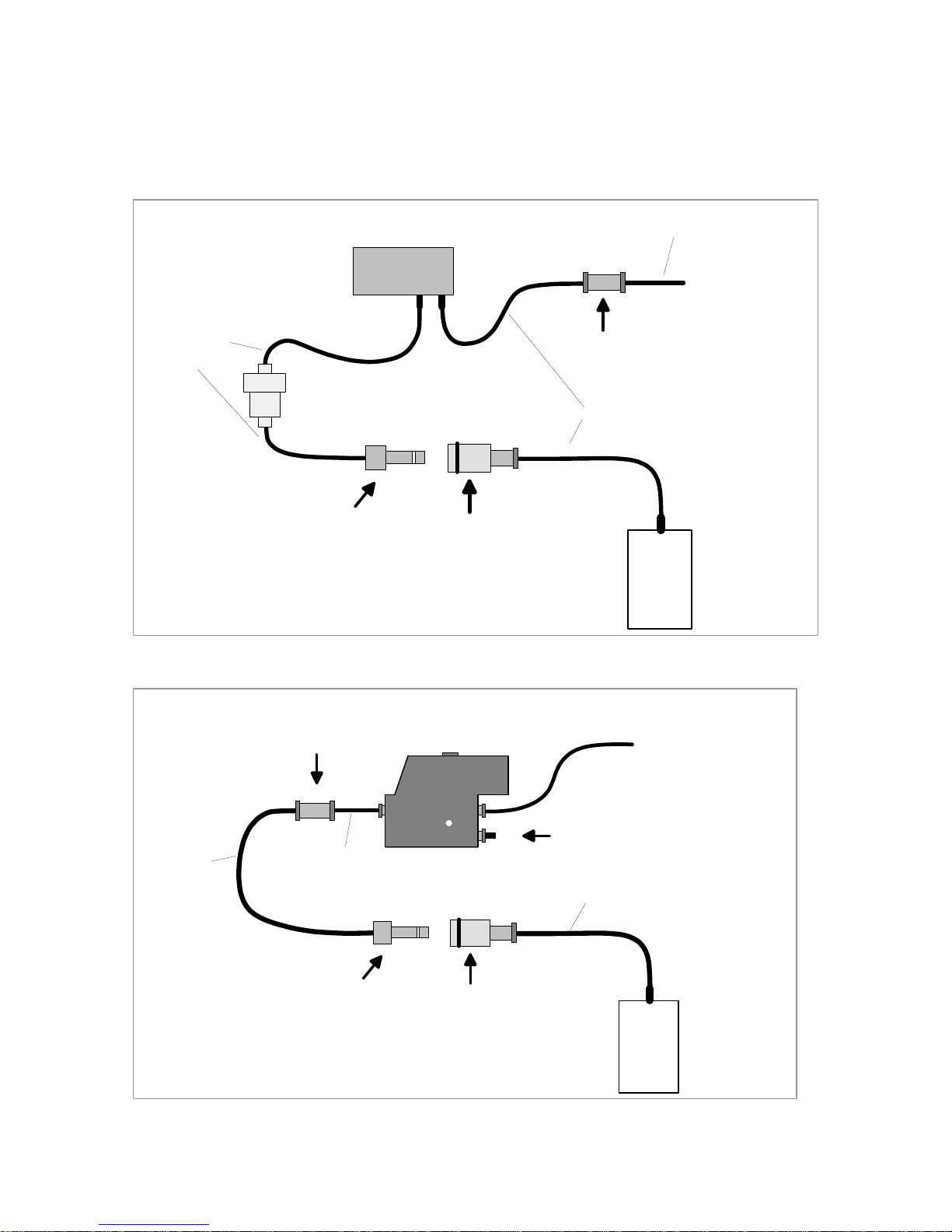
Electrical connection diagramm (1/2)....................................................................................................................6
Electrical connection diagramm (2/2)....................................................................................................................7
Power Supply............................................................................................................................................7
Charging the Battery.................................................................................................................................7
Glow Plug .................................................................................................................................................7
Fuel / Fuel Care.....................................................................................................................................................8
Fuel System..............................................................................................................................................8
Hopper Tank.............................................................................................................................................8
Fuel System Connection Diagram............................................................................................................9
Starting Gas Diagram.............................................................................................................................10
Filling the Starting Gas Tank:.................................................................................................................11
Mounting the Turbine...........................................................................................................................................12
Connections at the Turbine.................................................................................................................................13
The LED I/O Board..............................................................................................................................................14
Aligning the ECU to your R/C System.................................................................................................................15
Manual Mode.......................................................................................................................................................18
Turbine Starting / Running...................................................................................................................................19
Turbine Stopping / Cool Down.............................................................................................................................20
Manual Off..............................................................................................................................................20
Auto Off ..................................................................................................................................................20
Automatic Cooling Process ....................................................................................................................20
Battery / Fuel Warning Function..........................................................................................................................21
Turbine Running States.......................................................................................................................................21
Explanation of the Turbine States ..........................................................................................................21
Explanation for Turbine Shut Down........................................................................................................24
Ground Support Unit (GSU)................................................................................................................................25
GSU Control Panel Descriptions............................................................................................................25
GSU Switch Descriptions .......................................................................................................................26
GSU LED Descriptions...........................................................................................................................26
Menu Structure....................................................................................................................................................27
Menu Selections.....................................................................................................................................27
Selecting a Menu............................................................................................................................27
Change Values / Items ...................................................................................................................27
The RUN Menu.......................................................................................................................................28
The Min/Max Menu.................................................................................................................................28
The R/C Check Menu.............................................................................................................................28
The INFO Menu......................................................................................................................................29
The Statistic-Menu..................................................................................................................................30
The LIMITs Menu ...................................................................................................................................30
Troubleshooting...................................................................................................................................................31
Maintenance........................................................................................................................................................32
Parts List..............................................................................................................................................................33
Optional Accessories..............................................................................................................................33
Airspeed Sensor..................................................................................................................................................34

Page 3/39
Introduction
Welcome to the Jet Age of model aircraft! CAT is pleased to sell, support and service the
JetCAT P80 turbine engine and greatly appreciates your purchase. We hope the JetCAT P80
brings you many days of pleasurable flying.
Obviously, model turbine aviation - despite all the apparent fun involved - is serious business.
The JetCAT P80 has undergone extensive testing and redesign, in order to ensure it is a safe
and reliable model engine; however, it is not a recommended power source for the average
model builder. It requires a good background in model flying and a working understanding of
the principles of turbine engines, along with a disciplined commitment to correct and safe
operation, in accordance with these instructions.
To begin, read this manual thoroughly. Develop an overall impression of the engine and its
operating procedures, measuring equipment and accessories. Study the material step-by-step
and ascertain how to install, operate and maintain your turbine engine. If you are unsure about
anything, re-read it again.
DO NOT OPERATE THE JetCAT P80 BEFORE YOU HAVE READ THE MANUAL AND
FULLY UNDERSTAND EVERY PROCEDURAL DETAIL
Should you still have doubts or questions, do not hesitate to contact CAT for further assistance.
Once you are accustomed to handling the JetCAT P80, you will observe that it is a very reliable
engine. Some experienced operators have expressed their belief that it handles better than
many piston engines. However, always remember this is a REAL JET ENGINE, requiring
knowledge, discipline and maintenance.
In order to learn more about the development of the model turbine engine and understand its
function, we highly recommend reading Gas Turbine Engines for Model Aircraft by Kurt
Schreckling and Model Jet Engines by Thomas Kamps. These books are available through:
Traplet Publications
Traplet House
Severn Drive
Upton upon Severn, Worcestershire ISBN 0 9510589 1 6
United Kingdom WR8 0JL ISBN 0 9510589 9 1

Page 4/39
Safety Precautions
If other persons or animals are present while operating the JetCAT P80, ALWAYS ENFORCE
THE PROPER MINIMUM SAFE DISTANCES FROM THE TURBINE!
The recommended minimum safe distances are:
In front of the turbine = 15 feet
On the side of the turbine = 25 feet
Behind the turbine =15 feet
In case of a mishap, fire extinguishers should be on hand at all times. CAT recommends the
CO/2 variety. Powdered extinguishers will contaminate the precision components, upsetting the
integrity of the turbine.
To the avoid hearing damage, always use hearing protection when you are near a running
turbine engine!
When the turbine is running, never place your hands closer than six inches into the area of the
intake. An extreme suction - which can grasp a hand, fingers or other objects in a flash -
prevails in this area. Be aware of this source of danger, always!
Prevent foreign materials from entering the intake or exhaust when working with the turbine.
Before operation, make sure there are no lose parts or debris near the turbine. Objects being
sucked in can cause severe damage.
Always exercise caution around the hot parts of the turbine, to avoid burns. The outer case at
the turbine stage and nozzle reaches 450-500°(Celsius), while the exhaust gas may exceed
720 °C.
Assure that the fuel is mixed with approximately 5% synthetic oil. Use only synthetic turbine oils
available at local airport fuel suppliers or from CAT.
Never run the turbine in a closed room, or an area near any kind of flammable matter. Do not
fly turbine-powered aircraft near flammable materials, nor in forested tracts or areas
experiencing drought or dryness. Obey all forest fire regulations and warnings by refraining
from operating the JetCAT P80 in restricted fire zones. Never operate model turbine jet aircraft
in or around residential or heavily populated areas.
After running the turbine, briefly point the nose upward to assure that there is no fuel left in the
engine.
Installation of unauthorized parts from another manufacturing source may also result in engine
failure. Do not introduce engine or electronic components other than those delivered by CAT,
unless you are willing to risk destroying your turbine! CAT‘ parts are designed and engineered
specifically for the JetCAT P80. Accept no substitutes, unless you are prepared to sacrifice
your aircraft.

Page 5/39
Warning:
A flying model with a turbine can reach higher flight speeds than ducted fan-powered models,
because the turbine’s thrust degrades less with higher flight speeds. With attainable flight
speeds of over 250 MPH, you can quickly run out if flying room. There is also a danger of
developing control surface flutter or mechanical overload, causing the model to fail in flight.
When piloting a turbine powered aircraft, one must properly control the throttle. Full power
should be used for takeoff or vertical maneuvers and a reduced setting for level or descending
flight. To restrict the maximum flight speed, an optional airspeed sensor is available.
The Checklist
Before Running the Turbine
•Charge ECU Battery
•Prepare fire extinguisher
•Check fuel lines and filter. Make sure they are clean with no restrictions
•Check that the fuel tank vent is unobstructed
•Mix 5 % oil in fuel (i.e.: 1 quart per 5 gallons of kerosene)
•Fill fuel tank(s). Make sure the main and header tanks are full
•Be certain the starting gas release valve is closed, before filling the starting gas tank
•Turn on receiver switch
•Place the model with nose into the wind
•Activate brakes and start turbine
After Stopping the Turbine
•Turn model into the wind. Activate brakes and stop turbine
•After the cooling process (approximately two minutes), turn off receiver switch
•After each flying session, open starting gas release valve, to empty the tank, before storing
the model. This should be executed in a safe area

Page 6/39
Electrical connection diagramm (1/2)
AUXTHR
RC
receiver
(Empfänger)
"phone"- cable
("Telefonkabel")
The sequence of these connections can be changed as required (parallel bus system)
(Die Reihenfolge der Verbindungen spielt keine Rolle --> paralleles Bussystem)
Connection - diagramm
(Verbindungsschema)
ECU top-view
(von oben)
NiCad
battery (6 or 7cells)
(optional)
linked to a 3 position switch
on the RC-transmitter
(3-Stufenschalter)
Throttle stick
(Gaskanal)
Receiver-
battery
(Empfänger akku)
Receiver-
ON/OFF switch
(Empfängerschalter)
The ECU is automatically
powered up whenever the
receiver is switched on
(Die Elektronik schaltet sich automatisch EIN
sobald der Empfänger eingeschaltet wird)
Jet-tronic
Info Min/Max
Change
Value
Item
Select
Menu
Run Limits
++
-
Manual
Standby / Man.
Ignition
Ignition on
Pump running
OK / Reset...
Remote - GSU
Oilpump :max. 0.6A
FuzzylogicFuzzylogic
Microcomputer-
Control
Ba
tte
ry
:
7,2
-12
V
-
+
6-
10
Ce
lls
Te
mp
.&
Rp
m
Se
ns
or
Oil
pu
mp
Ai
rs
pe
ed
Jet-tronic -
II- P80
Pr
op
an
e
Sh
ut-
Off
val
ves
Da
ta-
BU
S
V2.0
Fu
el
-
+
-
+
"phone"- cable
("Telefonkabel")
LED I/O-
board
RS232
Adapter
PC
GSU =ground support unit
(Programmier- und Anzeigegerät)
Airspeed
Sensor air pressure
(Staudruck)
static pressure
(statischer Druck)
(optional)
Shut-off
valve
fuel
Shut-off
valve
propane
pitot-tube
(Staurohr)
6-wire phone cable to turbine
6-adriges Telefonkabel, zur Turbine
6-wire phone cable
6-adriges Telefonkabel

Page 7/39
Electrical connection diagramm (2/2)
Power Supply
Power for all electrical components of the turbine (starter / glow plug / ECU / fuel pump /
fuel and gas valves) are supplied by the six-cell, 1250 mah ECU battery. The amount
of battery capacity used per flight is approximately 300-400 mah. This includes starting
and cool down. The ECU NiCad battery must be recharged after three (3) flights! CAT
recommends recharging after every flight, making it a routine that is not overlooked.
The battery should be cycled periodically, to prevent NiCad memory problems that
lower the battery’s capacity.
Charging the Battery
Do not charge the battery, with a quick charger using negative discharge pulses, when
connected to the ECU. This will destroy the electronics of the ECU. The only
recommended method is to disconnect the battery from the ECU and charge it directly.
If you are absolutely sure that this is not the case with your charger, the battery can be
charged using an Y cable.
Glow Plug
A modified, conventional (hot range, non-idle bar) glow plug (Rossi #3) is appropriate.
The glow plug is installed on the turbine without a washer. Do not over-tighten or you
may damage the threaded bushing. Light torque is fine; there is no vibration to loosen
it. The glow plug is modified, so that two turns of the element extend beyond the bottom
of the plug. With a pin, pull out two turns of the element. Make sure the plug glows
brightly red. The limits menu features an adjustment for glow plug voltage, if needed.
This adjustment is described later.
Connection - diagramm (2/2)
(Verbindungsschema)
ECU bottom-view
(von unten)
Glow-plug
Starter device
Fuel-pump
Outputs are unfused !
max. 12A
Fuzzylogic
Microcomputer-Control
Jet-tronic -II- P80
-
To turbine (3 wire cable)
(Zur Turbine 3-adriges Kabel)
Fuelpump
(Kraftstoffpumpe)

Page 8/39
Fuel / Fuel Care
The JetCAT P80 can use Jet-A1, 1-K kerosene or deodorized kerosene for fuel. Fuel
must be mixed with 5% synthetic turbine oil.
Example formula: 1 quart of oil in 5 gallons of fuel.
Oil brands like Aeroshell 500 or Exxon 2380 are suitable.
Fuel System
If a header tank is used, the clunk is placed in the main tank. Otherwise, place the
clunk in the last tank before the fuel valve. Do not use a felt clunk. The supplied
clunk is designed to reduce the amount of bubbles in the fuel line.
When installing the fuel lines on components with nipples, slightly heat the tubing
before connecting. This will soften the tube, making it easier to install. When installing
tubing on a metal tube, secure the tubing by placing a tie-wrap around the connection.
To remove tubing from nipples, you must cut the tubing off. Be careful not to damage
the nipple when cutting off tubing. To insert tubing into Festo quick release fittings, use
firm pressure until you feel the tube snap in. To release, press in on the front ring, while
pulling the tubing out.
ALWAYS use a gasoline-compatible stopper. Silicon stoppers swell and leak.
Check your fuel filters every ten (10) flights. You may be surprised how rapidly they can
clog up! The filter is installed with the O-ring located toward the fuel shut-off valve.
When running the engine at full power, check the fuel line from the pump to the engine.
If there is a large quantity of air bubbles flowing with the fuel, there is probably a
restriction in the fuel system or an air leak in a fitting.
Hopper Tank
A hopper tank is strongly recommended, between the main fuel tank and the engine.
Using a hopper tank greatly lessens the possibility of air bubbles in the fuel system,
thus reducing the risk of a flameout. The hopper tank should accommodate
approximately two to four (2 to 4) ounces and the fuel pickup should be a brass tube,
positioned in the center of the tank. Do not use a clunk.

Page 9/39
Fuel System Connection Diagram
Hoppertank
main tank ( Haupttank)
Sinterpendel
Entlüftung
Filter
to turbine (zur Turbine)
in
out
Shut-off
valve
( Ventil )
Fuelpump
(Pumpe)
tank fill connector
(Befüllungsanschluß)
hopper-tank

Page 10/39
Starting Gas Diagram
Version 1
Version 2
gastank fill connector
(Befüllungsanschluß
selbstabsperrend,
Kupplungsdose)
do not remove stopper !
(Blindstopfen nicht entfernen !)
gastank fill connector
male
(Kupplungsstecker)
4 -> 3mm tubing adaptor
4 -> 3mm Schlauchadapter
3mm tubing to turbine
3mm Schlauch zur Turbine
(Hilfsgas) Turbine
4mm tubing
4mm Schlauch 3mm tubing
3mm Schlauch 4mm tubing
4mm Schlauch
gastank
shut-off valve propane
Gasventil
connector allways up !
Anschluß immer nach oben !
gastank fill connector
(Befüllungsanschluß
selbstabsperrend,
Kupplungsdose)
gastank fill connector
male
(Kupplungsstecker)
4 -> 3mm tubing adaptor
4 -> 3mm Schlauchadapter
3mm tubing to turbine
3mm Schlauch zur Turbine
(Hilfsgas)
Turbine
4mm tubing
4mm Schlauch
4mm tubing
4mm Schlauch
gastank
connector allways up !
Anschluß immer nach oben !
Shut-off
valve
( Ventil )
Filter

Page 11/39
Important:
The starting gas tank can be mounted vertically or horizontally. Whether the tank is
mounted upright or on its side, the offset nipple must always be towards the top. This
will prevent liquid propane from entering the turbine during startup. After every flying
session, disconnect the release valve, before storing the model.
The starting gas shut-off valve should be placed as close to the turbine as possible.
This insures that the gas will not be restricted by the capillary effect of a long delivery
tube.
Filling the Starting Gas Tank:
Only use a propane/butane mix for starting gas. CAT recommends Coleman
POWERMAX fuel (or a mix of propane butane 60/40%). POWERMAX is available at
sporting goods stores or from CAT. Use the 10.6-ounce size.
Do not use 100% propane from torch refill bottles. The pressure is too high and will
cause the tubing to rupture.
To fill the tank, connect the fill connector of the gas refill bottle to the selfshutting
connector starting gas tank in the model. Put the POWERMAX fuel can upside down,
then open the valve at the refill bottle (àliquid gas is flowing into the starting gas tank)
Verify that the fluid is flowing into the tubing. Continue filling, until the fluid slows or
stops. Just before the liquid stops flowing put the refill bottle back to the upright
position. Although several starts are attainable with a full tank, CAT recommends
refilling before every flight, establishing a routine that is not overlooked.
Gasfüllflasche
(Propan/Butan
Gemisch )
Bunsenbrenner (Lötbrenner)
Aufsatz modifiziert
4mm Messingrohr eingelötet
4mm tubing
4mm Schlauch
4mm Messingrohr eingelötet4mm Messingrohr eingelötet4mm Messingrohr eingelötet4mm Messingrohr eingelötet4mm Messingrohr eingelötet4mm Messingrohr eingelötet
4mm Schlauchverbinder Kupplungsstecker Kupplungsdose Gastank

Page 12/39
Mounting the Turbine
A two-piece, aluminum mounting bracket is included with the turbine. Place the bracket
around the turbine, with the glow plug situated within the slot of the smaller bracket
piece. This will help stabilize the engine along the thrust axis. The glow plug must be
in the vertical position, when mounted in your model (+/- 45°of engine rotation, from the
glow plug at top dead center, is the allowable deviation). Secure the engine, using four
metric mounting screws and lock washers that are provided with brackets.
For models that require an exterior turbine mount (such as the Kangaroo) or for bypass
tube mounting, optional brackets are available from CAT.

Page 13/39
Connections at the Turbine
Fuel Connector,
4mm tubing from
the fuel pump
From ECU,
EGT & RPM
sensor cable
Starting Gas
Connector,
(Propane/ Butane)
3mm tubing from the
starting gas tank
From ECU
(Glow-plug /
Starter device)
3-lead cable

Page 14/39
The LED I/O Board
The LED I/O (Input/Output) board is a connection point for the data bus and a display
for the current status of the ECU. The board should be mounted with the LED’s visible
and the data bus connector accessible for GSU plug-ins. The connector facing
opposite of the LED’s is attached to the ECU. The LED I/O board also features a
pushbutton switch function - to learn your R/C system (when powered up), or for
entering the MANUAL mode (when power is already on). These procedures are
described later.
Illustration 1:
Explanation of the Lights on the LED I/O board. These LED indicators are identical to
the GSU LED’s (excluding the red “ignition on“).
Color Name LED On LED Blinks
Yellow Standby Starter Motor engauged Manual Mode is active
Red Pump Running Fuel pump is on Glow Plug is defective
Green OK / Reset… Turbine running:
throttle control active 1. If the turbine is running, the
EGT is exceeding the
maximum temperature.
2. If the turbine is off,
SlowDown mode active
Special function:
If the yellow Standby/Manual and green OK LED’s blink simultaneously, the battery is
low and must be recharged.

Page 15/39
Aligning the ECU to your R/C System
Before the Jet-Tronic ECU can be used for the first time, throttle stick and auxiliary
control positions must first be programmed.
To accomplish this, complete the following steps:
1. Connect the two ECU servo cables to the receiver. The “THR” cable connects to the
throttle channel and the “AUX” cable must be connected to a channel capable of
three (3) positions. Make certain that all other connections are made in accordance
with the Electrical Connection Diagram.
2. Inspect the transmitter programming, to ensure that dual rates and exponential
functions are disabled, travel is set at 100% and sub trim is set at zero for both
channels.
3. While pressing the “Select Menu” button on the GSU, switch on the receiver.
Helpful hint:
Instead of the Select Menu button on the GSU, the small switch on the LED I/O
board may be pressed instead. This button can also be used to advance
through the “learn R/C” sequence (described below). This feature is useful when
the GSU is not available. Keep in mind that the LED’s on the I/O board are the
same as the GSU for “Standby/Manual”, “Pump running” and “OK”.
Release Select Menu only after the three LED’s display the following blink
sequence:
LED Blink Sequence
Standby/Man. Yellow ¤¡¡¤¡¡
Pump running Red ¡ð ¤ ð ¡ ð ¡ ð ¤ ð ¡
OK Green ¡¡¤¡¡¤....
The GSU display will simultaneously read:
4. This procedure enables a system mode, whereby the stick positions can be learned
by the ECU. When Select Menu is released, only the green OK LED should
illuminate.
The GSU display will read:
àAlternate “Off” position
Release key to:
- learn RC -
Set Throttle to
minimum:
- learn RC -

Page 16/39
5. Now the ECU can memorize the positions of the throttle and AUX channels. First,
place the throttle stick and throttle trim to low. Next, press Select Menu or the LED
I/O board switch, again. This will store the R/C system’s pulse width for immediate
shutdown of the turbine. The green OK LED will turn off and the red Pump running
LED will illuminate. This indicates that the shutdown data has been set correctly.
The GSU display will read:
àThrottle channel “Idle” position
6. Advance the throttle trim lever to maximum. Press Select Menu or the LED I/O
board switch again, to store the R/C system’s pulse width for the turbine idle position.
The red Pump running LED will turn off and the yellow Standby/Manual LED will
illuminate. This indicates that the turbine idle data has been set correctly.
The GSU display will read:
àThrottle channel “Full Power” position
7. Advance the throttle stick to maximum. Press Select Menu or the LED I/O board
switch again, to store the R/C system’s pulse width for the turbine full power position.
The yellow Standby/Manual LED will turn off and the green OK LED will illuminate
again, indicating that the turbine full power data has been set correctly. This
completes the learn mode for throttle and initiates the learn mode for the three-
position AUX channel.
The GSU display will now read:
àAUX channel minimum “Off” position.
8. Move the AUX channel to the minimum position for Off and press Select Menu or
the LED I/O board switch again, to store the R/C system’s pulse width for immediate
shutdown of the turbine. The green OK LED will turn off and the red Pump running
LED will illuminate. This indicates that turbine shutdown data has been set correctly.
Throttle Trim
to maximum:
- learn RC -
Set Throttle to
maximum:
- learn RC -
Set AuxChan. to
MINIMUM:
- learn RC -

Page 17/39
The GSU display will read:
àAUX channel middle “Start/Standby” position
9. Set the AUX channel to the middle position for Start/Standby and press Select
Menu or the LED I/O board switch again, to store the R/C system’s pulse width for
the turbine to start and run. The red Pump running LED will turn off and the yellow
Standby/Manual LED will illuminate. This indicates that the turbine start/standby
data has been set correctly.
The GSU display will read:
àAUX channel maximum “Auto-Off” position
10. Place the AUX channel on the maximum position for Auto-Off and press Select
Menu or the LED I/O board switch, to store the R/C system’s pulse width for a
normal shut-off of the engine. The yellow Standby/Manual LED will turn off and the
ECU will now permanently store the data. This indicates that the “learn R/C”
procedure is completed and the ECU now retains the pre-set stick position values.
Repeating this procedure is only necessary when the R/C system is changed or
adjusted.
Set AuxChan. to
CENTER:
- learn RC -
Set AuxChan. to
MAXIMUM:
- learn RC -

Page 18/39
Manual Mode
During normal ECU function, the operator has no direct control of the fuel pump or fuel
shutoff valve. To prime the fuel pump and fuel lines (or for fuel pump test purposes), it
is necessary to open the fuel shutoff valve and run the fuel pump manually. For this
purpose, the ECU has a special feature that opens the fuel valve and acts as a speed
control for running the pump.
II Extremely Important:
Manual mode allows the fuel pump to operate without the turbine running. However, if
the fuel feed line is not removed from the turbine during this procedure, it will become
flooded with fuel. When this occurs, the next turbine start can become highly
combustible!
Before activating the manual mode, ALWAYS remove the fuel feed line connected
to the turbine.
To activate manual mode, the AUX switch must be Off and the throttle stick and trim to
their minimum positions. All LED’s will be off. Manual mode can now be activated by
pressing the GSU MANUAL button or by pressing the small switch on the LED I/O
board. When manual mode is active, the yellow Standby/Manual LED will blink and
the fuel shutoff valve opens. Move the AUX switch to the Start/Standby (middle)
position, and the throttle stick can then actively control the fuel pump. Returning the
throttle stick to its idle position will stop the fuel pump.
In manual mode, by placing the AUX switch in the Auto-Off position, the throttle stick
will work as an on/off switch for the fuel pump. When the throttle stick is advanced from
idle, the fuel pump will run at a steady pre-programmed speed – the minimum setting
that will reliably run the pump. If the throttle stick is returned to idle, the pump will shut
off. During startup, this speed is used to establish initial voltage for the fuel pump.
Manual mode may be disengaged by two separate methods:
•Press the MANUAL button on the GSU or the LED I/O board switch, a second time.
•By repositioning the AUX switch back to its Off setting.
The yellow Standby/Manual LED will stop blinking!

Page 19/39
Turbine Starting / Running
1. Prepare to start by completing the startup checklist (previously described on page
5).
2. Briefly hold the model upward, to ensure there is no residual fuel in the turbine.
3. Set the AUX switch to the Off position. All LED’s will be off.
4. Move the throttle trim lever to idle (maximum) position.
5. Set the AUX switch to the Start/Standby (middle) position.
6. If the throttle stick is not at the idle position, the LED’s will blink in a continuous
sequence of yellow to red to green. Bring the throttle stick to the idle position,
changing the LED blink sequence to green to red to yellow, continuously. The
turbine is now ready to start!
7. Advance the throttle stick to its maximum setting and the turbine will start.
8. Once the turbine begins to accelerate, the throttle stick can be returned to idle
position. As soon as the turbine stabilizes at idle speed, the green OK LED will
illuminate, indicating that thrust control is now handed over to the pilot. The throttle
stick must be in the idle position, for the green OK LED to illuminate.
When the throttle stick is set to the maximum position (Step 7 ÜBER), the ECU will
begin a fully automatic starting sequence. This starting sequence can be immediately
disengaged, by moving the AUX switch to the Off position.
After the start process is initiated, the following occurs:
1. The starting motor spins the turbine rotor up to approximately 2,500-3,500 RPM -
then the starting motor is stopped.
2. Next, the glow plug is switched on and the starting gas valve opened.
3. The speed of the turbine begins to fall slowly, while ignition normally occurs during
this period. Should ignition not occur, the starter will automatically make more
attempts. If the turbine does not ignite, during a 30-second period of attempts, the
process is aborted and the green OK LED will blink.
4. As soon as ignition occurs, the yellow Standby/Manual LED will illuminate and the
starting motor is re-engaged to accelerate the turbine. At approximately 5000 RPM,
the fuel pump switches on and the red Pump running LED illuminates.
5. Turbine speed will progressively increase until achieving stable speed. When the
turbine speed surpasses the idle RPM value, the starter motor disengages and the
yellow Standby/Manual LED goes out.
6. As the turbine approaches approximately 55,000 RPM, it will briefly stabilize, before
automatically decelerating to idle RPM.
7. When the turbine attains idle speed and the throttle stick is placed at idle position,
the green OK LED will illuminate, indicating that thrust control is now handed over to
the pilot.

Page 20/39
Turbine Stopping / Cool Down
To shut off the turbine, there are two methods:
Manual Off
Turbine immediately turns off!
At anytime, the turbine can immediately be switched off manually by:
•setting the three-position AUX switch to Off
OR •bringing the throttle stick to idle position, while bringing the throttle trim to its
minimum position
Auto Off
Turbine automatically turns off!
This is the normal way of shutting down the turbine:
When the three-position AUX switch is moved to the Auto-Off position, the following
happens:
The turbine automatically stabilizes at around 55,000 RPM, for approximately six
(6) seconds, before shutting down. This allows the turbine to run at an optimal
temperature, drawing in a large quantity of cool air through the turbine, as it
shuts off. This automatic off function can be discontinued at any time, by
returning the AUX switch back to the Start/Standby position, before the turbine
shuts down.
Automatic Cooling Process
After the turbine spins down from Auto Off or Manual Off, the starter motor will
periodically spin the turbine rotor, if the Exhaust Gas Temperature is above 100°C.
This happens at regular intervals, for about one minute or longer.
II Extremely Important:
In unsafe situations (e.g.: a model fire), the automatic cooling process may
contribute dangerous, additional oxygen. To immediately discontinue the cooling
process, bring the throttle stick to idle, throttle trim to the minimum position and
the AUX switch to Off.
Table of contents
Popular Toy manuals by other brands

V-tech
V-tech Write & Learn Artboard user manual

Step 2
Step 2 Clubhouse Climber 8012 manual

V-tech
V-tech V.Smile Baby: Noah s Ark Animal Adventures user manual

Sky Angel
Sky Angel 35MM Nano Series Assembly and operating manual

LaserPegs
LaserPegs GI270B instruction manual

PLAYTIVE JUNIOR
PLAYTIVE JUNIOR HK-2592 Instructions for use

Spinmaster
Spinmaster Umagine Cool Baker Cake Pop Maker quick start guide

Stevens Aero Model
Stevens Aero Model QuickOats100 Build instructions

V-tech
V-tech Kidizoom Lightning McQueen Digital Camera user manual

Pro Boat
Pro Boat Miss Elam 1/12 owner's manual

J. Perkins
J. Perkins easy pigeon user manual

Techone
Techone SWIFT 3D-EPP instruction manual