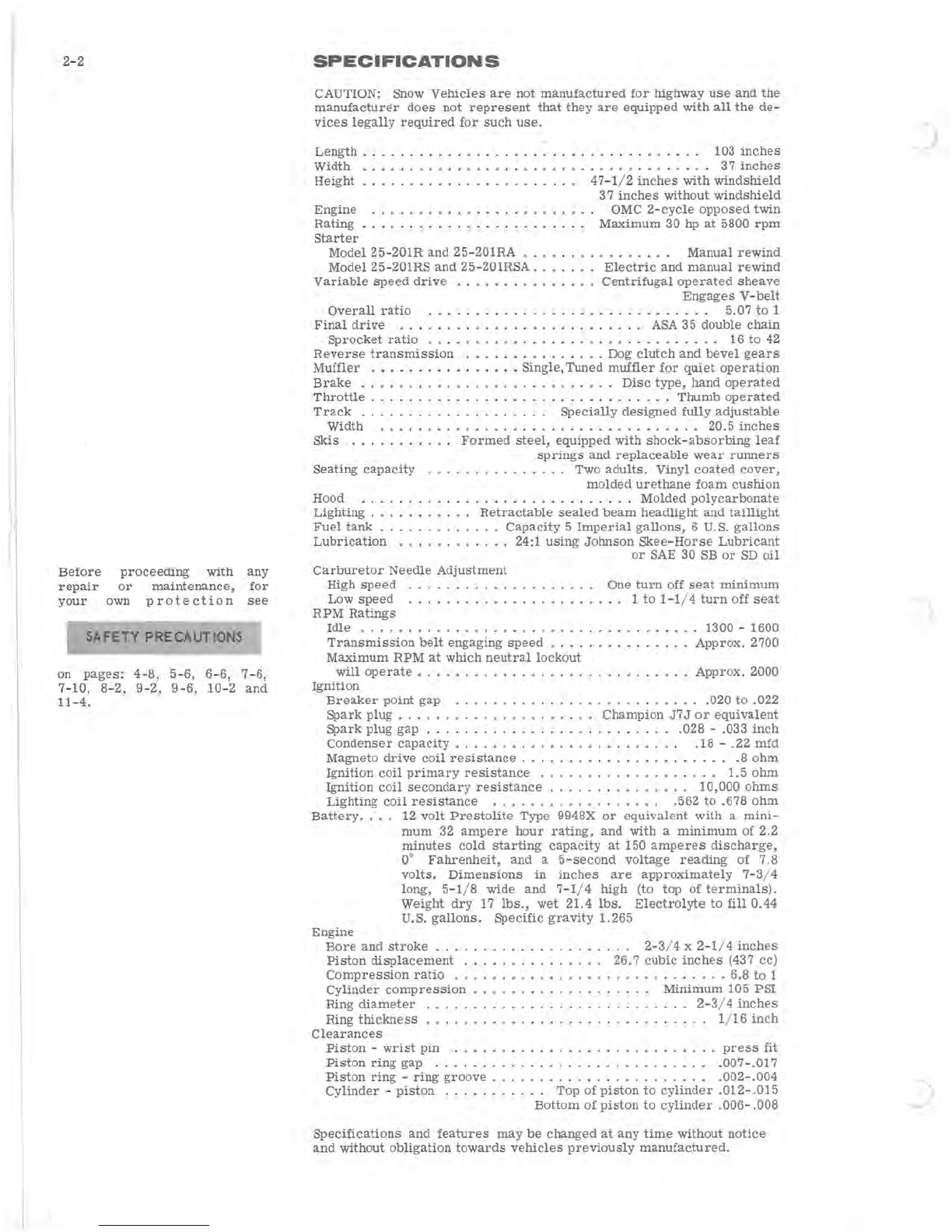
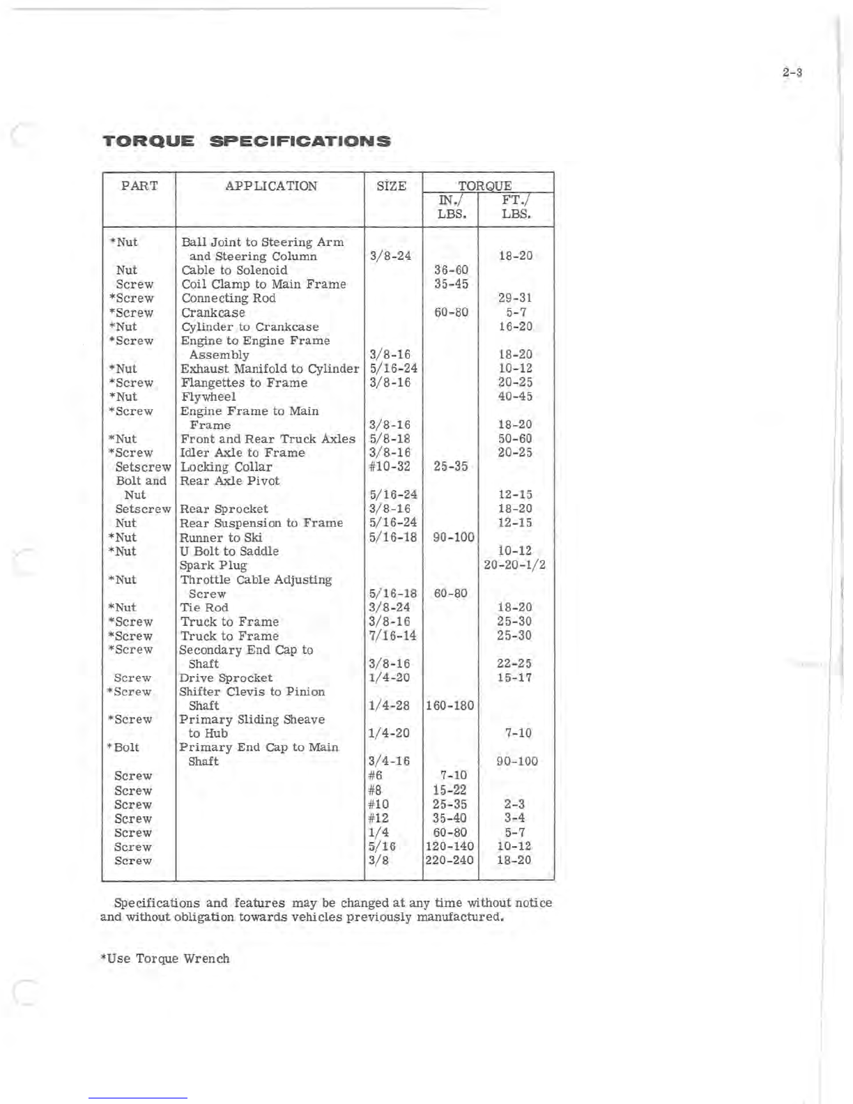
Johnson SKEE-HORSE 25-201R User manual

•.
_ .. _ . _:
-:
.
__
:.
: _'_•.
~-
_
~
~~
.
____
..
...._
••.
.:
..
:
••.
_ .·
_.o
•
..
..:
.
:
.
-".
~
!
..
..
..
_'.0
.-
.;.,
.
...,.
-
..
..-.
;.
..-
___
~-O:
• ...l-. -
~
~.o-·
.
~
..
..
--"
-'
"
~DhnsDn
· ·
SKEE-HORSE
SERVICE
MANUAL
o
30
HORSEPOWER
MODELS
25-201R
25-201RA
25-201RSA
11
·
70
PART
NO.
261894
LITHO
U.S.A.
©
OUTBOARD
MARINE
CORPORATION
1970
ALL
RIGHTS
RESERVED

AVAILABLE
IN
ONE
QUART
CANS
AND
IN
6
PACKS
FROM
YOUR
JOHNSON
DEALER
170
2.0
FUEL
RECOMMENDATIONS
The
correct
fuel
mixture
ratio
is
24
parts
of
a
good
grade
regular
gaso-
line
to
one
part
lubricant.
For
ease
of
measurement,
this
is
equivalent
to
one
quart
of
lubricant
to
six
gallons
of
gasoline,
one
pint
of
lubricant
to
three
gallons
of
gasoline,
or
1/3
pint
of
lubricant
to
each
gallon
of
gasoline.
Use
only
Johnson
Lubricant
or
a
reputable
automotive
engine
oil,
SAE 30
SD
or
SB.
Avoid
use
of low
price
third
grade
(SA
light
duty)
oils.
DO
NOT USE
MULTIPLE
VISCOSITY OILS, SUCH
AS
10W30, OR
ANY OUTBOARD MOTOR OILS
OTHER
THAN JOHNSON OUTBOARD
LUBRICANT.*
*EVEN THOUGH JOHNSON OUTBOARD LUBRICANT
IS
ADVER-
TISED
AS
A 50:1 RATIO LUBRICANT, IT
IS
IMPERATIVE
FOR
SNOWMOBILE USE THAT IT
BE
MIXED AT A 24:1
GAS-
LUBRICANT RATIO.
DO NOT POUR GASOLINE OR LUBRICANT
DIRECTLY
INTO
VEHICLE
FUEL
TANK. USE
AN
APPROPRIATE
CONTAINER
FOR
MIXING
AND
STORING
THE
FUEL
.
To
prepare
the
snowmobile
fuel
properly,
pour
into
a
SEPARATE,
clean
container
half
the
amount
of
gasoline
required
and add
all
the
required
lubricant.
Thoroughly
shake
this
partial
mixture.
Next,
add
the
balance
of
gaso-
line
necessary
to
bring
the
mixture
to
the
required
ratio
of
24:l.
Again,
thoroughly
agitate
the
mixture.
A
clean
funnel
equipped
with
a
fine
screen
should
be
used
when
pouring
the
fuel
mixt~re
into
the
vehicle
tanle
24
to
1
lubricant
is
prediluted
to
provide
excellent
mixability
with
gaso-
line
at
low
temperatures.
The
addition
of
this
dilutent
does
not
in
any
way
affect
the
lubrication
qualities
of
the
lubricant.
Whenever
is is
necessary
to
mix
fuel
and
lubricant
at
temperatures
below
0°
F,
the
lubricant
should
be
prediluted
with
gasoline
to
improve
its
mixability.
The
lubricant
should
be
prediluted
with
approximately
one
part
gasoline
to
one
part
lubricant.
Predilution
of
the
lubricant
should
take
place
with
the
lubricant
temperature
above
O°F.
Do
not
use
kerosene
or
fuel
oils
for
pre-mixing.

SECTION
1
INTRODUCTION
INTRODUCTION
SPECI
FI
CA
TID
NS
GENERAL
SNOWMOBI
LE
IN
FO
RMATION
TROUBLE
SHOOTING
TUNE
-
UP
PROCEDURES
FUEL
'
SYSTEM
IGNITION
AND
ELECTRICAL
SYSTEM
MANUAL
STARTER
ENGINE
DRIVE
TRAIN
STEERING,
TRACK
AND
SUSPENSION
LUBRICATION
AND
STORAGE

1-2
1
The
snow
machine
has
been
designed
and
built
for
dependable,
high )
performance.
It
is
important
to
every
snow
machine
owner
to
be
ab
le
to
receive
skilled
and
thorough
service
for
his
vehicle
when
necessary.
It
is
important
to
the
service
dealer
to
be
able
to
offer
the
type
of
skilled
service
which
will
maintain
the
customer's
satisfaction.
This
manual,
together
with
the
regularly
issued
service
bulletins
and
Parts
Catalogs,
provide
the
serviceman
with
all
the
literature
necessary
to
service
the
Skee-Horse·
snowmobiles.
An
effort
has
been
made
to
produce
a
manual
that
will
not
only
serve
as
a
ready
reference
book
for
the
experienced
serviceman,
but
will
also
provide
more
basic
informa-
tion
for
the
guidance
of
the
less
experienced
man.
The
Parts
Catalogs
contain
complete
listings
of
the
parts
required
for
replacement.
In
addition,
the
exploded
views
illustrate
the
correct
sequence
of
all
parts.
This
catalog
can
be
of
considerable
help
as
a
reference
during
disassembly
and
reassembly.
The
Section
Index on
page
1-1
enables
the
reader
to
locate
quickly
any
desired
section.
At
the
beginning
of
each
Section
is
a
Table
of
Contents
which
gives
the
page
number
on
which
each
topic
begins.
This
arrange-
ment
simplifies
locating
the
desired
information
within
this
manual.
Section
2
lists
complete
specifications
on
the
1971
snowmobiles.
All
general
information,
including
2
cycle
engine
theory,
trouble
shooting,
and
tune
up
procedures,
are
given
in
Sections
3
through
5 of
this
manual.
17029
Figure
1-1

(
Sections 6
through
11
provide
fully "
illustrated,
detailed,
step-by-step
disassembly
and
reassembly
instructions
and
adjustment
procedures.
Section 12
provides
lubrication
and
storage
information.
In
this
way,
the
texts
treat
each
topic
separately;
theory
and
practice
are
not
intermixed.
This
makes
it
unnecessary
for
the
experienced
service-
man
to
reread
discussions
of
theory
along with
specific
service
in-
formation.
lliustrations
placed
in
the
margins
provide
unimpeded
reading
of
explanatory
text,
and
permit
close
relationship
between
illustration
and
text.
Read
this
manual
carefully
to
become
thoroughly
familiar
with
the
procedures
described,
then
keep
it
readily
available
in
the
service
shop
for
use
as
a
reference.
If
properly
used,
it
will
enable
the
serviceman
to
give
better
service
to
the
snowmobile owner, and
thereby
build and
maintain
a
reputation
for
reliable
service.
This
service
manual
covers
all
phases
of
servicing
the snowmobile,
however,
new
service
situations
sometimes
arise.
If
a
service
question
does
not
appear
to
be
answered
in
this
manual, you
are
invited
to
write
to
the
Service
Department
for
additional help. Always
be
sure
to give
complete
information,
including model
number
and
vehicle
serial
number.
All
information,
illustrations,
and
specifications
contained
in
this
literature
are
based
on
the
product
information
available
at
the
time
of
publication.
The
right
is
reserved
to
make
changes
at
any
time
without
notice.
1.
Instrument
Panel
Door
10.
Speedometer/Odometer
2.
Neutral
Lockout
(Accessory)
3.
Reverse
Control
11.
Throttle
4. Headlight
Retracting
Lever
12.
Primer
5. Hand
Brake
and
Parking
Lock
6.
Tachometer
(Accessory)
7. Choke
8.
Fuel
Level
Gauge
9.
Compression
Release
13.
Ignition/Lights
Switch
14. Manual
Starter
Handle
15.
Lighter
(Electric
Start
Models)
Figure
1-2
1-3
I
I
J

)
)
J

c
(
(
TABLE
OF
CONTENTS
2-1
SECTION
2
SPECIFICATIONS
SPECIFICATIONS.
. . . . . • . . • . • . . . . • .
2-2
TORQUE
SPECIFICATIONS
..••...•.•.
2-3
I
I
I

I
I
J
2-2
Before
repair
your
proceeding
with
or
mai
n
tenance,
own
protection
SAFJ;'
.
TY
PRECAUTIONS
",
any
for
see
on
pages:
4-8,
5-6,
6-6,
7- 6,
7-10,
8-2,
9-2,
9-6,
10-2
and
11-4.
SPECIFICATION
S
CAUTION: Snow
Vehicles
are
not
manufactured
for
highway
use
and
the
manufacturE!r
does
not
represent
that
they
are
equipped
with
all
the
de-
vices
legally
required
for
such
use.
Length
.......
.
Width
.....
. .
Height
......
.
Engine
Rating
.
....
Start
er
. . . . . . . . . . . . . .
..
103
inches
.
.......
......
37
inches
47-1
/ 2
inches
with
windshield
37
inches
without
windshield
OMC
2-cycle
opposed
twin
Maximum
30 hp
at
5800
rpm
Model
25-201R
and
25-201RA
......
.
Manual
rewind
Model 25-201RS
and
25-201RSA . . .
Electric
and
manual
rewind
. . . . . . .
Centrifugal
operated
sheave
Engages
V-belt
Variable
speed
drive
..
Overall
ratio
. . . . . . . . . . . . . . . . .
..
5.07
to
1
Final
drive
........................
ASA 35 double
chain
Sprocket
ratio
. .
......
.....
....
.....
....
.
....
16
to
42
Reverse
transmission
...
......
..
.
...
Dog
clutch
and
bevel
gears
Muffler
.•..•
.
••.....•••
Single,
Tuned
muffler
for
quiet
operation
Brake
......
.
........
Disc
type,
hand
operated
Throttle.
. . . . . . . . . . . .
....
.........
.
Thumb
operated
Track
...
. . . . . . . . . .
Specially
designed
fully
adjustable
Width . . . . . . . . . . . . . . . . . . . . . . . . . 20.5
inches
Skis
...........
Formed
steel,
equipped
with
shock-absorbing
leaf
springs
and
replaceable
wear
runners
Seating
capacity
......
........
Two
adults.
Vinyl
coated
cover,
molded
urethane
foam
cushion
Hood .
....
..
'. . . . . . . . . . . . . . .
Molded
polycarbonate
Lighting
. . . . . . .
Retractable
sealed
beam
headlight
and
taillight
Fuel
tank.
. . . . .
...
Capacity
5
Imperial
gallons,
6 U.S.
gallons
Lubrication
.........
...
24:1
using
Johnson
Skee-Horse
Lubricant
Carburetor
Needle
Adjustment
High
spe
ed
.........
.
Low
speed
...........
.
RPM
Ratings
or
SAE 30 SB
or
SD
oil
One
turn
off
seat
minimum
...
1
to
1-1/4
turn
off
seat
Idle
..................
.
.......
. . 1300 -1600
Approx.
2700
Transmissi
on
belt
engaging
speed
..•.......
Maximum
RPM
at
which
neutral
lockout
will
operate
....................
.
Approx.
2000
Ignition
Breaker
point
gap
..........................
020
to
.022
Spark
plug.
. . . . . . .
........
Champion
J7J
or
equivalent
Spark
plug
gap . . . . . . . . . . . . . . . . . . . .
..
.028 -.033
inch
Condenser
capacity
......................
"
.18
-.22
mfd
Magneto
drive
coil
resistance.
. . . . . . . . . . . . . . . . . . .
..
.8
ohm
Ig
niti
on
coil
primary
resistance
...................
1.5
ohm
Ignition
coil
secondary
resistance
. . . . . . . . . . . . .
..
10,000
ohms
Lighting
coil
resistance
.
...
............
..
.562
to
.678
ohm
Battery.
.
..
12
volt
Pr
estolite
Type
9948X
or
equivalent
with
a
mini-
mum
32
ampere
hour
rating,
and
with
a
minimum
of
2.2
minutes
cold
starting
capacity
at
150
amperes
discharge,
0°
Fahrenheit,
and
a
5-second
voltage
reading
of
7.8
volts.
Dimensions
in
inches
are
approximately
7-3
/ 4
long, 5-1/ 8 wide
and
7-1
/ 4
high
(to
top
of
terminals).
Weight
dry
17
lbs.,
wet
21.4
lbs.
Electrolyte
to
fill
0.44
U.S.
gallons.
Specific
gravity
1.265
Engine
Bore
and
stroke
.................
.
Piston
displacement
........
.
Compression
ratio
.........
.
Cylinder
compression
... ...
....
. .
Ring
diameter
Ring
thickness
.................
.
Clearances
Piston
-
wrist
pin
.....
.
2-3
/ 4 x
2-1
/ 4
inches
26.7
cubic
inches
(437 cc)
.
............
6.8
to
i
Minimum
105
PSI
. . .
..
2-3
/ 4
inches
. . . . . . . 1/ 16
inch
. . . . . . . .
press
fit
Pist
on
ring
gap
..
.
...........
, .007-.017
Piston
ring
-
ring
groove
.
Cylinder
-
piston
.....
. . . . . . . . . . . .
..
.002-.004
.
..
Top
of
piston
to
cylinder
.012-
.015
Bottom
of
piston
to
cylinder
.006-
.008
Specifications
and
features
may
be
changed
at
any
time
without
notice
and
without ob
ligation
towards
vehicles
previously
manufactured.

(
TORQUE
SPECIFICATIONS
PART
APPLICATION
SiZE TORQUE
IN.
/
FT./
LBS. LBS.
*Nut
Ball
Joint
to
Steering
Arm
and
Steering
Column 3
/8
-24 18-20
Nut Cable
to
Solenoid
36-60
Screw
Coil
Clamp
to
Main
Frame
35-45
*Screw
Connecting
Rod
29-31
*Screw
Crankcase
60-80 5-7
*Nut
cYlinder
to
Crankcase
16
-
20
*Screw
Engine
to
Engine
Frame
Assembly
3/ 8-16 18-20
*Nut
Exhaust
Manifold
to
Cylinder
5/16
-
24
10-12
*Screw
FlangeUes
to
Frame
3/ 8-16 20-25
*Nut
Flywheel
40-45
*Screw
Engine
Frame
to
Main
Frame
3/ 8-16
18
-
20
*Nut
Front
and
Rear
Truck
Axles
5/8
-
18
50-60
*Screw
Idler
Axle
to
Frame
3/ 8-16 20-25
Setscrew
Locking
Collar
#10-32
25
-
35
Bolt
and
Rear
Axle
Pivot
Nut
5/ 16-24 12-15
Setscrew
Rear
Sprocket
3/ 8-
16
18-20
Nut
Rear
Suspension
to
Frame
5/ 16-24 12-15
*Nut
Runner
to
Ski 5/ 16-18 90-100
*Nut U
Bolt
to
Saddle
10-12
Spark
Plug
20
-
20-1/2
*Nut
Throttle
Cable
Adjusting
Screw
5/
16
-
18
60-80
*
Nut
Tie
Rod
3/ 8-
24
18-20
.
*Screw
Truck
to
Frame
3
/8
-16
25
-
30
*Screw
Truck
to
Frame
7
/1
6-14 25-30
*Screw
Secondary
End
Cap
to
Shaft
3/ 8-
16
22-25
Screw
Drive
Sprocket
1/ 4-20 15-17
*Screw
Shifter
Clevis
to
Pinion
Shaft
1/4-28
160-180
*
Screw
Primary
Sliding
Sheave
to
Hub
1/4-20
7-10
*
Bolt
Primary
End
Cap
to
Main
Shaft
3/4-16
90-100
Screw
#6 7-10
Screw
#8
15
-
22
Screw
#10 25-35 2-3
Screw
#12
35
-
40
3-4
Screw
1/4
60-80 5-7
Screw
5/
16
120-
140
10-12
Screw
3/8
220-240
18
-
20
Specifications
and
features
may
be
changed
at
any
time
without
notice
and
without
obligation
towards
vehicles
previously
manufactured.
*Use
Torque
Wrench
2-3

)
J

(
r
3- 1
SECTION
3
GENERAL
SNOWMOBILE
INFORMATION
TABLE
OF
CONTENTS
TWO-CYCLE
ENGINE
OPERATION.
. . . .
..
3-2
CARBURETION
.•.•................
3-3
IGNITION.
. . . . . . . . . . . . . . . . . . . . . .
..
3-3
POWER
FLOW.
. . . • . . . . . . . . . . . . . .
..
3-4
PRIMARY
DRIVE
.................
3-4
NEUTRAL
LOCKOUT.
. . . . . . . . . . . .
..
3-5
SECONDARY DRIVE
.............•.
3-5
REVERSE
TRANSMISSION
...........
3-5
I
I
I

j
'I
3-2
POWER
STROKE
-
DOWN
COMBUSTION
OF
FUEL-AIR
MIXTURE
CONNECTING
COUNTER-
ROD
BALANCE
AXIS
OF
ROTATION
F i
gur
e
3-1
171 33
FUEL
INTAKE
AND
EXHAUST
LEAF
VALVES
EXHAUST
PORT
OPEN
Figur
e
3-2
17134
COMPRESSION
STROKE
-
UP
FUEL
FROM
EXHAUST
PORT
CLOSED
Figure
3-3
17
13
5
TWO
CYCLE
ENGINE
THEORY
An
internal
combustion
engine
is
one
in
which
fuel
is
burned
inside
the
engine:
a
charge
of
fuel
is
introduced
into
a
combustion
chamber
(cylinder)
within
the
engine
and
ignited.
The
energy
released
by
the
expansion
of
the
burning
fuel
is
converted
to
torque
by
the
piston,
con-
necting
rod,
and
crankshaft.
Internal
combustion
engines
are
classified
as
either
four-cycle
or
two-cycle
engines.
The
"four"
and
the
"two"
refers
to
the
number
of
piston
strokes
required
to
complete
a
power
cycle
of
intake,
compres-
Sion,
power
,
and
exhaust.
A
piston
stroke
is
piston
travel
in
one
direc
-
tion
only; up
is
one
stroke,
down
is
another.
In
a
four
-
cycle
engine,
two
crankshaft
revolutions,
or
four
strokes,
are
required
for
each
power
cycle.
In
a
two-cycle
engine
only one
crankshaft
revolution
is
required
per
power
cycle.
In
a
two-cy
c
le
engine
,
the
ignition
of
the
fuel-air
mixture
occurs
as
the
piston
reaches
the
top
of
each
stroke.
The
expansion
of
gases
drives
the
piston
downward
(see
Figure
3-1).
Toward
the
end
of
the
downward
stroke,
ports
which
lead
from
the
cylinder
to
the
exhaust
system
are
uncovered.
The
expanding
exhaust
gases
flow
into
these
ports,
reducing
pressure
in
the
cylinder.
Immediately
after,
intake
ports
are
opened.
These
ports
connect
the
cylinder
with
the
crankcase
where
a
mixture
of
fuel
and
air
has
been
developed
by
carburetion.
The
downward
motion
of
the
piston
compresses
this
mixture
and
forces
it
through
the
intake
ports
into
the
cylinder.
See
Figure
3-2.
The
inrushing
charge
of
the
fuel-air
mixture
helps
to
eject
(scavenge)
the
last
of
the
exhaust
gases
from
the
cylinder.
At
this
point,
the
mo
-
mentum
of
the
flywheel
is
required
to
return
the
piston
to
the
top of
the
cylinder
.
As
the
piston
begins
its
up-stroke,
it
closes
the
intake
and
exhaust
ports
and
begins
to
compress
the
fuel-air
mixture
trapped
in
the
cylinder.
See
Figure
3-3.
The
upward
motion
of
the
piston
also
re
-
du
ce
s
the
pressure
in
the
crankcase.
The
resulting
crankcase
suction
opens
leaf
valves
which
admit
a
fresh
charge
of
air
and
fuel
from
the
carburetor
into
the
crankcase,
thus
preparing
for
the
next
power
cycle.
Near
the
top
of
the
piston
stroke,
the
compressed
fuel-air
mixture
is
ignited,
the
piston
is
driven
downward,
and
the
power
cycle
is
repeated.
At
full
throttle,
this
cycle
may
be
repeated
more
than
five
thousand
times
every
minute.
CARBURETION
The
system
which
controls
the
intake
of
the
fuel-air
mixture
in
the
two
cycle
engine
consists
of
a
set
of
leaf
valves
which
serve
the
same
purpose
as
the
intake
valves
on
a
four
cycle
engine.
The
leaf
valves
are
thin,
flexible
metal
strips
mounted
between
the
carburetor
intake
manifold
and
crankcase.
When
the
piston
is
on
the
up-stroke,
it
creates
a
partial
vacuum
in
the
crankcase.
Atmospheric
pressure
forces
the
leaves
away
from
the
body
(see
Figure
3-4),
opening
the
passage
between
the
carburetor
and
crankcase.
When
the
piston
is
on
the
down-stroke,
it
compresses
the
crankcase
charge,
forcing
the
leaves
against
the
passage
opening,
and
sealing
off
the
crankcase
from
the
carburetor.
Since
the
opening
and
clOSing
may
occur
in
excess
of
five
thousand
times
per
minute,
the
leaves
must
be
thin
and
flexible.
)

(
~.
Gasoline,
in
its
liquid
state,
burns
relatively
slowly
with
an
even
flame.
.
However,
when
gasoline
is
combined
with
air
to
form
a
vapor,
the
mixture
becomes
highly
inflammable
and
burns
with
an
explosive
effect.
To
obtain
best
results,
the
fuel
and
air
must
be
correctly
pro-
portioned
and
thoroughly
mixed.
It
is
the
fWlction of
the
carburetor
to
accomplish
this.
Gasoline
vapor
will
burn
when
mixed
with
air
in a
proportion
from
12:1
to
18:1 by weight.
Mixtures
of
different
proportions
are
required
for
different
purposes.
Idling
requires
a
relatively
rich
mixture;
a
leaner
mixture
is
desirable
for
maximum
economy
under
normal
load
conditions;
avoid
lean
mixtures
for
high
speed
operation.
The
carbure-
tor
is
designed
to
deliver
the
correct
proportion
of
fuel
and
air
to
the
engine
for
these
various
conditions.
The
carburetor
is
essentially
a
Simple
metering
device.
The
float
chamber
holds
a
limited
quantity
of
fuel,
regulated
by a
float
valve.
Needle
valves
permit
a
precise
amount
of
fuel
to
flow
from
the
float
chamber
to
the
carburetor
throat.
The
upstroke
of
the
piston
creates
a
suction
which
draws
air
through
the
leaf
valves
and
the
carburetor
throat.
At a
particular
point
the
throat
is
restricted
by
a
venturi
(see
Figure
3-5).
The
venturi
has
the
effect
of
reducing
air
pressure
in
the
air
stream,
creating
a
partial
vacuum
which
draws
fuel
from
the
jet
nozzles.
As
it
is
rushed
along
to
the
firing
chamber,
the
fuel
is
swirled
about
in
the
air
stream
and
vaporized.
A
shutter
or
butterfly
valve
in
the
throat
regulates
the
amount
of
air
drawn
through
the
carburetor.
To
vary
the
speed
of
the
engine,
the
throttle
shutter
opens
or
closes,
regulating
the
amount
of
fuel-air
mix-
ture
drawn
into
the
engine.
A
richer
fuel
mixture
is
required
for
starting
a
cold
engine.
A
sec-
ond
shutter,
called
a choke,
is
placed
into
the
throat
forward
of
the
jets,
to
restrict
the
flow
of
air.
When
the
choke
shutter
is
closed,
more
gas
-
oline
and
less
air
is
allowed
into
the
air
stream
resulting
in
a
richer
fuel-air
mixture.
When
normal
operating
temperature
is
reached,
the
choke
is
opened
and
the
standard
ratio
of
gasoline
and
air
allowed
to
flow
from
the
carburetor.
IGNITION
The
ignition
system
provides
a
high
voltage
electric
current
which
causes
a
spark
to
jump
the
spark
plug
gap
within
the
cylinder
and
thus
ignite
the
compressed
fuel-air
mixture
in
the
cylinder.
The
ignition
system
consists
of
the
magneto
drive
COilS,
breaker
points,
and
con-
denser,
and
the
ignition
coil
assemblies.
Permanent
magnets
built
into
the
flywheel
revolve
around
the
magneto
drive
coils.
As
the
magnet
moves
past
the
coils,
the
direction
of
the
magnetic
flux
through
the
coil
is
changed
from
one
direction
to
the
other
(see
Figure
3-6).
Self-
inductance
of
the
magneto
drive
coil
circuit,
completed
through
the
breaker
pOints,
prevents
the
flux
in
the
coil
laminations
from
changing
until
the
breaker
pOints open. When
the
points
open,
the
flux
changes
direction
very
rapidly,
inducing
a
current
which
flows
through
the
ignition
coils'
primary
windings.
The
ignition
coils
transfrom
this
cur-
rent
to
a
very
high
voltage
which
is
sufficient
to
discharge
across
the
spark
plugs'
gap.
The
lighting
system
coils
produce
alternating
current
which
changes
in
frequency
and
voltage
in
proportion
to
the
engine
speed.
On
models
having
electric
starting,
this
alternating
current
output
is
converted
to
direct
current
by
a diode
bridge
rectifier
and
used
to
charge
the
bat-
tery.
Direct
current
from
the
battery
is
then
used
to
power
the
head-
light
and
taillight,
and
the
electric
starter
motor.
3-3
HOLE
FOR
FUEL
PUMP
PULSE
ACTION
JNTAKE
MANIFOLD
GASKET
L
EAVES
LEAF
PLATE
AND
BASE
ASSEM.
17088
Figure
3-4
INDUCED
LOW
~VENTURI
PRESSURE
:::..~~~~
..
i~ib
FUEL
FORCED
UPWARDS
BY
ATMOSPHERIC
PRESSURE
Figure
3-5
P -
PERMANENT
MAGNET
N -
NORTH
POLE
SHOE
S -
SOUTH
POLE
SHOE
F -
FLYWHEEL
C -
LAMINATED
COIL
CORE
17136
-
17137
Figure
3-6

3-4
NEUTRAL
LOCKOUT
POSITION
Figure
3-7
A.
Neutral
Lockout
Plunger
B.
Emergency
Starting
Sheave
C.
Garter
(Activating)
Spring
D. End Cap
E.
Movable
Half
of
Sheave
POWER
FLOW
The
transmission
assembly
transmits
power
from
the
engine
to
the
front
axle
which
propels
the
vehicle
along
the
track.
The
primary
sheave
assembly
is
attached
directly
to
the
crankshaft.
The
secondary
sheave
assembly
has
its
own mounting
pedestal
and
is
larger
in
diam-
eter
than
the
primary
sheave
assembly.
The two
are
connected
by
a
transmission
belt.
PRIMARY
DRIVE
The
primary
sheave
is
centrifugally
operated
and
engages
the
trans-
mission
belt
when
the
engine
speed
reaches
approximately
2700
rpm.
When
the
engine
is
rotating
at
idle
speed
or
below
2700
rpm,
the
trans-
mission
belt
rides
on a
ball
bearing
between
the
halves
of
the
primary
sheave
assembly
(see
Figure
3-7).
The
primary
sheave
assembly
halves
are
separated
by
a
compression
spring
in
the
hub
of
the
movable
sheave
half.
As
the
engine
speed
increases,
centrifugal
effect
forces
a
garter
spring
in
the
end
cap
outward
against
the
contour
of
the
end
cap
and
axially
against
the
movable
sheave
half. As
the
sheaves
are
brought
together
the
transmission
belt
is
forced
outward
to
ride
on
a
larger
diameter
of
the
primary
sheave
assembly,
increasing
belt
speed
(see
Figure
3-8).
Since
the
belt
length
remains
constant,
the
secondary
sheave
halves
spread
apart,
allowing
the
belt
to
ride
on a
smaller
diameter.
In
this
way,
the
engine
transmits
power
through
a
variable
ratiO,
presenting
the
engine
with
a
mechanical
advantage
most
favorable
for
the
speed
at
which
it
is
operating.
ENGAGED
POSITION
17171
171n
Figure
3-8
F.
Transmission
Belt
M.
Splined
Shaft
G.
Fixed
Half
of
Sheave N.
Bolt,
End
Cap
to
Splined
H.
Crankshaft
Shaft
I.
Ball
Bearing
O.
Spring
J.
Spring Cup
P.
Neutral
Lockout Rod
K.
Compression
Spring
R.
Spring
L.
Neutral
Lockout
Balls
)

(
(
NEUTRAL
LOCKOUT
A
neutral
lockout
mechanism
is
used
to
prevent
the
drive
from
en-
gaging
during
starting,
warm-up
period,
and
idle.
When
the
neutral
lockout
plunger
is
actuated,
a cone on
the
end of
the
plunger
raises
two
balls
through
the
splines
of
the
primary
sheave
assembly
and
into
the
path
of
the
movable
sheave
half,
preventing
it
from
engaging
the
belt.
The
neutral
lockout
is
spring
actuated
and will engage only when
the
engine
is
below
approximately
2000
rpm.
When
the
engine
is
running above
approximately
2000
rpm,
the
garter
spring
will
expand by
centrifugal
effect. See
Figure
3-9.
The
garter
spring
will
then
ride
up
the
ramp
of
the
end cap and
push
the
movable
sheave
toward
the
fixed
sheave.
In doing
this,
the
movable
sheave
has
covered
the
holes
in
the
splined
shaft.
When
the
neutral
lockout
knob
is
now
pushed
in,
the
plunger
cannot move
in
because
of
the
interference
by
the
neutral
lockout
balls.
Spring
(R)
will
therefore
be
compressed
as
shown
in
Figure
3-9.
If
the
engine
speed
is
now
reduced
to
idle,
1300-1600
rpm,
the
garter
spring
will
close
and allow
the
movable
half
of
the
sheave
to
move away
from
the
fixed
sheave.
Spring
(R)
will
then
push
the
plunger
inward.
The
neutral
lockout
balls
will
then
move
outward,
through
the
splined
shaft.
The movable
sheave
will
now
be
locked
out
in
the
neutral
position.
See
Figure
3-7.
SECONDARY DRIVE
The
secondary
drive
mechanism
incorporates
a
torque
sensing
device
that
detects
the
need
for
more
power
for
steep
inclines
or
deep snow.
The
mechanism
immediately
forces
the
secondary
sheaves
closer
to-
gether
to
lower
the
transmission
ratio
and
provide
a
higher
torque
to
the
drive
chain
and
track.
The
drive
ratio
varies
from
3.3
to
1
in
low
to
.67
to
1
in
high which
yields
an
overall
drive
range
to
approximately
5
to
1.
Power
is
trans-
mitted
from
the
secondary
sheave
assembly
through
a
drive
chain
to
the
front
axle.
The
ratio
between
the
secondary
sheave
assembly
and
the
front
axle
is
16:42. Optional
sprockets
are
available
to
change
these
ratios
for
special
applications.
REVERSE
TRANSMISSION
The
reverse
gear
is
designed
as
part
of
the
secondary
drive.
In
"Forward"
gear,
the
input
shaft
drives
the
output
shaft
directly
by
means
of a "dog"
type
clutch.
In
"Reverse"
gear,
the
dog
clutch
is
released
while a
gear
set
engages
to
reverse
rotation
of output
shaft.
Shifting
must
be
done with
the
engine
at
idle
and machine
at
rest.
POSITION
AT
APPROXIMATELY
2000
RPM
WITH
NEUTRAL
LOCKOUT
ROD
DEPRESSED
Figure
3-9
17275
3-5

/
)
)
)

(
4-1
SECTION
4
TROUBLE
SHOOTING
TABLE
OF
CONTENTS
DESCRIPTION.
. . . . . . . . . . . . . . . . . . .
.•
4-2
COMPRESSION
. . . . . . . . . . . • . . . . . • •
••
4- 2
SPARK
PLUGS
.•.....•.•.•.........
4-3
TROUBLE
SHOOTING
PROCEDURES.
. . . .
..
4-4
TROUBLE
SHOOTING GUIDE
...........
4- 7

4-2
DESCRIPTION
This
section
provides
trouble
shooting
procedures
for
the
snow
ma-
chine.
Steps
to
be
followed
in
determining
causes
of
unsatisfactory
per-
formance
are
outlined.
A
Trouble
Check
Chart
at
the
end
of
this
section
lists
causes
of
unsatisfactory
performance.
Being
able
to
locate
the
cause
of
trouble
in
an
improperly
operating
snow
mach.ine
is
as
important
as
being
able
to
correct
the
trouble.
A
systematic
approach
to
trouble
shooting
is
important
if
the
trouble
is
to
be
located
and
identified
in
minimum
time.
Any
service
operation
can
be
broken
down
into
three
steps:
1.
Identifying
the
problem
2.
Determining
the
cause
of
the
problem,
and
3.
Correcting
the
problem.
Familiarity
with
the
factors
which
affect
two-cycle
engine
perform-
ance
is
important
in
making
a
correct
service
diagnosis.
Factors
which
affect
engine
performance
include
the
quality
of
the
fuel
and
fuel
mix-
tures,
compression,
spark
and
spark
plug
operation,
and
proper
drive
system
adjustment.
This
section
discusses
compression
and
spark
plugs
and
their
relation
to
performance.
A
complete
discussion
of
fuel
mixtures
is
included
in
Section
12.
Familiarity
with
factors
which
con-
tribute
to
abnormal
performance
of
an
engine
are
similarly
helpful.
The
skilled
mechanic's
experience
is
a
great
asset
here.
The
Trouble
Check
Chart
at
the
end
of
this
section
will
assist
in
tracing
symptoms
of
trouble
to
the
source.
COMPRESSION
The
pistons
and
piston
rings
perform
two
functions.
They
compress
the
mixture
of
fuel
and
air
in
the
cylinders
before
ignition,
and
receive
the
force
of
the
power
after
ignition.
For
maximum
compression,
the
cylinder
must
be
round
and
the
piston
and
piston
rings
correctly
fitted
to
it.
The
rings
must
be
properly
seated
in
the
ring
grooves
and
free
to
expand
against
the
walls
of
the
cylinder.
The
rings
will
not
retain
the
force
of
combustion
if
the
pistons
and
cylinder
walls
are
excessively
worn,
scored,
or
otherwise
damaged,
or
if
the
rings
become
stuck
in
grooves
because
of
carbon
accumulation.
Escape
of
compression
past
the
piston
rings
is
referred
to
as
"blow-by"
and
is
indicated
by
dis-
coloration
or
carbon
formation
on
the
piston
skirt.
Cylinder
bores
normally
wear
with
operation
of
the
engine.
The
de-
gree
of
wear
will
vary
with
length
of
operation,
efficiency
of
lubricatioh,
and
general
condition
of
the
engine.
Excessive
cylinder
wear
results
in
loose
fitting
pistons
and
rings,
causing
blow-by,
loss
of
compression,
loss
of
power
and
inefficient
performance
.
Piston
rings
are
formed
·
in
such
a
manner
that
when
installed
on
the
piston,
they
bear
against
the
cylinder
wall
with
a
light,
even
pressure.
Excessive
ring
pressure
against
the
cylinder
wall
increases
friction,
causing
high
operating
temperature,
sluggish
performance,
and
abnor-
mal
wear
or
scoring.
Insufficient
pressure
allows
blow-by,
which
re-
duces
power,
and
causes
overheating
and
carbon
formation
on
the
piston
skirt.
Since
the
ring
tends
to
flex
as
it
follows
the
cylinder
contour
during
engine
operation,
clearance
or
gap
must
be
provided
between
the
ring
ends
to
prevent
butting.
The
ring
gap
also
allows
the
ring
to
expand
)
)
)

(
r
(elongate)
as
engine
temperature
rises
during
operation.
Insufficient
gap
clearance
will
cause
the
ring
to
bend
or
warp
as
it
flexes
and
ex-
pands;
excessive
gap
clearance
will
permit
loss
of
compression.
Compression
leakage
may
also
occur
at
the
spark
plugs.
A
cracked
spark
plug
insulator
will
cause
similar
trouble.
Although
compression
is
primarily
dependent
on
the
piston,
rings,
and
cylinder,
these
other
sources
of
leakage
should
be
investigated
when
compression
loss
is
noted.
Compression
leakage
will
occur
if
the
compression
relief
valve
link-
age
is
adjusted
with
insufficient
clearance
on
the
cable
ends.
The
re-
lief
valves
vent
combustion
chamber
pressure
through
a
by-pass
port
into
the
exhaust
system.
Compression
may
also
be
affected
by
the
fuel
induction
and
exhaust
systems.
Since
the
fuel
vapor
is
first
compressed
in
the
crankcase,
leakage
here
will
affect
engine
performance.
Possible
trouble
spots
include
leaf
valve
assemblies,
seals
between
crankcase
halves,
and
crankshaft
bearing
seals.
Exhaust
ports
which have
become
clogged
because
of
excessive
deposits
of
carbon
will
hinder
the
efficient
transfer
of
exhaust
gases.
Excessive
carbon
build-up
on
piston
heads
or
elsewhere
in
the
cyl-
inder
walls
can
result
in
a
loss
of power.
Following
the
trouble
check
chart
provided
at
the
end
of
this
section
and
the
recommended
tune-up
procedures
given
in
Section 5 will
assure
that
all
areas
affecting
fuel
induction,
compression,
and
exhaust
will
be
considered
as
part
of
every
trouble
shooting
procedure.
An
engine with
low
or
uneven
compression
cannot
be
successfully
tuned
for
peak
per-
formance.
It
is
essential
that
improper
compression
be
corrected
be-
fore
proceeding
with
an
engine
tune-up.
SPARK
PLUGS
The
spark
plug
provides
a
gap
inside
the
combustion
chamber
across
which
the
high
voltage
from
the
ignition
coil
can
be
discharged.
The
resulting
spark
ignites
the
compressed
mixture
of
fuel
vapor
and
air
in
the
cylinder.
See
Figure
4-1.
Spark
plugs
are
made
in
a
number
of
heat
ranges
to
satisfy
a
variety
of
operating
conditions.
The
heat
range
of a
spark
plug
refers
to
its
ability
to
dissipate
heat
from
its
firing
end
to
the
cylinder
head.
The
heat
range
established
for
any
spark
plug
is
determi.ned
in
design
by
the
length
of
the
path
which
the
heat
from
the
tip
must
travel
to
the
thread
and
seat
area
where
it
is
transferred
to
the
cylinder.
Spark
plugs
having a
short
gap
between
the
firing
end of
the
center
electrode
and
the
thread
and
seat
area
are
used
for
hot
running
engines
(see
Figure
4-2).
Snowmobiles
used
in
heavy
load
conditions
(ie. deep snow
or
sled
towing)
will
run
the
engine
temperature
higher,
and
in
this
case,
a
colder
plug
might
be
recommended.
Spark
plugs
operating
under
these
conditions
must
remain
cool enough
to
avoid
preignition
and
excessive
gap
erosion.
Spark
plugs
having a long
gap
transfer
heat
sl
ower
and
are
used
on
cooler
running
engines.
See
Figure
4-3.
Cooler
running
en-
gines
have a
relatively
low
combustion
chamber
temperature,
therefore
a high
spark
plug
temperature
must
be
sustained
in
order
to
burn
off
normal
combustion
deposits
and
avoid
fouling.
For
most
effective
sparking
through
any
rpm
range
and
under
all
conditions
of
operation,
the
electrode
and
insulator
tip
temperature
must
be
kept
high enough
to
vaporize
or
burn
off
particles
of fuel
mixture
which
collect
on
the
insulator.
Low
plug
temperatures
result
in
electrode
fouling
by
an
accumulation
of
unburned
fuel
particles,
carbon
bits,
sludge,
etc.
Se-
lection
of
the
correct
spark
plugs
for
an
engine
depends
on
the
type of
service
to
which
it
will
be
subjected.
A
cold
running
engine
will
require
a hot
plug
and
a hot
running
engine,
a cold plug.
Spark
plug
recom-
mended
for
use
on
the
Ski-Horse
snowmobile
is
the
Champion
J7J
or
equivalent.
See
page
7-8
for
additional
information
on
spark
plugs.
GROUND
ELECTRODE
Figure
4-1
COOL
PLUG
Figure
4
-2
HOT
PLUG
Figure
4-3
4-3
CENTER
I
17138
/1
I
I
I
17139
17139

4-4
TROUBLE
SHOOTING
PROCEDURES
Trouble
shooting
to
determine
the
cause
of
any
operating
problem
may
be
broken
down
into
the
following
steps:
a.
Obtaining
an
accurate
description
of
the
trouble.
b.
Quick
tune-up.
c.
Use
of
Trouble
Check
Chart
to
analyze
engine
performance.
An
accurate
description
of
the
trouble
is
essential
for
trouble
shooting.
The
owner's
comments
may
provide
valuable
information
which
will
serve
as
a
clue
to
the
cause
of
the
problem.
Find
out
pertinent
facts
such
as:
a.
Correct
spark
plugs
b.
Throttle
linkage
properly
adjusted
c.
Tank
filled
with
fresh,
clean
fuel
of
the
proper
mixture
d.
Spark
at
each
spark
plug
e.
Carburetor
adjusted
correctly
f.
Compression.
Turn
flywheel
by hand
or
with
recoil
starter.
If
compression
is
present,
it
can
be
felt
when
turning
through
one
complete
revolution
of
the
flywheel.
If
little
or
no
com-
pression
exists
in
both
cylinders,
engine
will
spin
very
easily.
STARTING
1.
Hard
to
start
or
won't
start
a.
Empty
gas
tank
b.
Incorrect
gas-lubricant
ratio
c.
Old
fuel,
or
water
or
dirt
in
fuel
system
d.
Fuel
line
improperly
connected
e.
Fuel
line
kinked
or
severely
pinched
f.
Engine
not
primed
g.
Clogged
fuel
line
or
fuel
filter
h.
Clogged
check
valve
i.
Carburetor
adjustments
too
lean
j.
High
speed
needle
bent
or
bowed
k.
Engine
flooded
1.
Leaf
valves
not
functioning
properly
m.
Faulty
gaskets
n.
Spark
plugs
fouled,
improperly
gapped,
dirty
or
broken
o.
Loose
or
broken
wire
or
frayed
insulation
in
electrical
system
p.
Sheared
flywheel
key
q.
Faulty
coils
r.
Faulty
condenser
s.
Binding
in
engine
t.
Weak
or
reversed
polarity
of
flywheel
magnets
2.
Engine
won't
crank
over
a.
Cylinder
wall
corrosion
b.
Broken
connecting
rod,
crankshaft,
or
drive
shaft
c.
Engine
improperly
assembled
after
repair
3.
Cranks
over
extremely
easily
a.
Spark
plug
loose
b.
Cylinder
or
pistons
scored
c.
Hole
burned
in
piston
head
d.
Rings
worn
4.
Won't
start,
but
kicks
back
and
backfires
a.
Flywheel
key
sheared
b.
Timing
out
of
adjustment
c.
Leaf
valves
broken
or
not
seating
STARTING -MANUAL
STARTER
1.
Manual
starter
pulls
out,
but
starter
does
not
engage
flywheel
a.
Friction
spring
bent
or
burred
b.
Excess
or
incorrect
grease
on
pawls
or
spring
c.
Pawls
bent
or
burred
d.
Pawls
frozen
(water)
in
place
2.
Starter
rope
does
not
return
a.
Recoil
spring
broken
or
binding
b.
Starter
housing
bent
This manual suits for next models
3
Table of contents