CONTENTS
3
USE AND MAINTENANCE INSTRUCTIONS FOR THE USER
1.1 Introduction - AIR HEATING FOGO and FOGHEA
.........................................................................................................................................................................
4
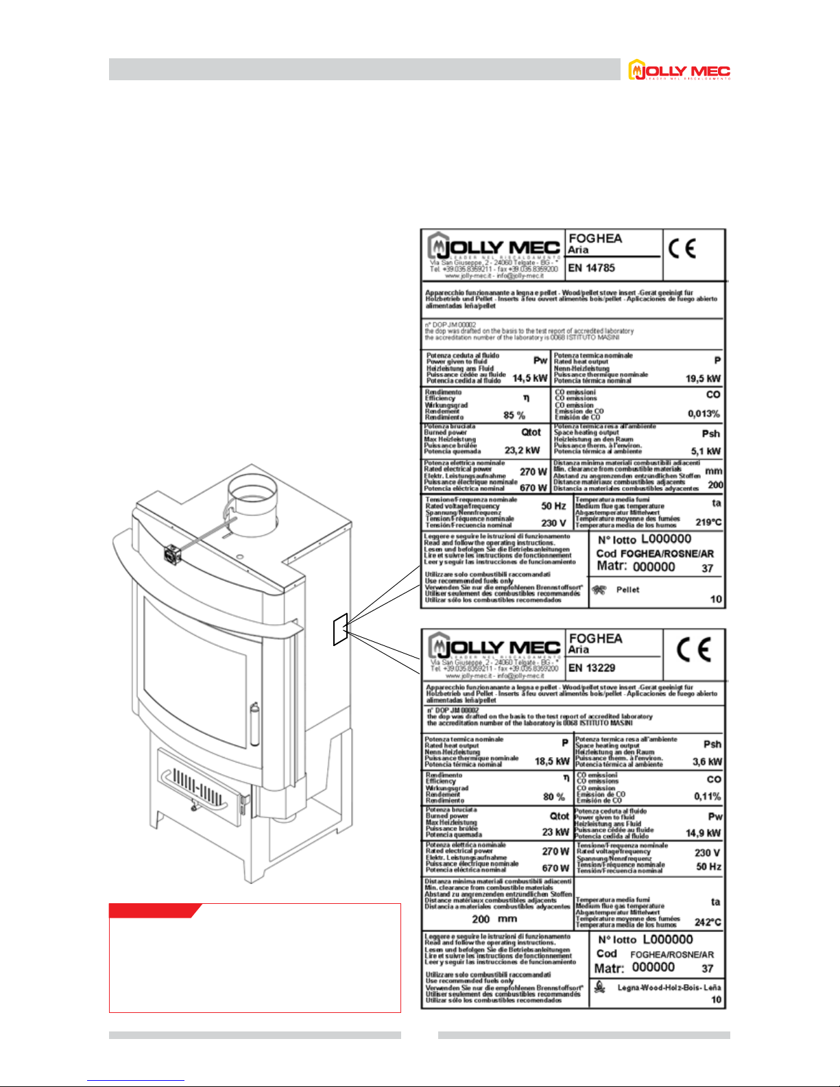
1.2 Stove identication
...............................................................................................................................................................................................................................................
5
1.3 Technical specications
.....................................................................................................................................................................................................................................
6
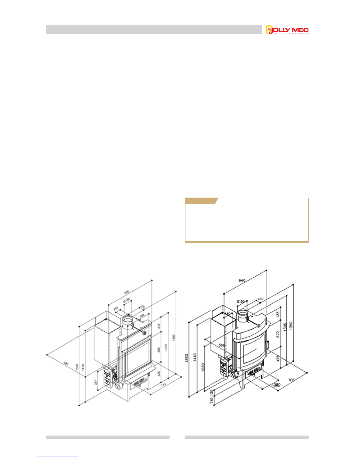
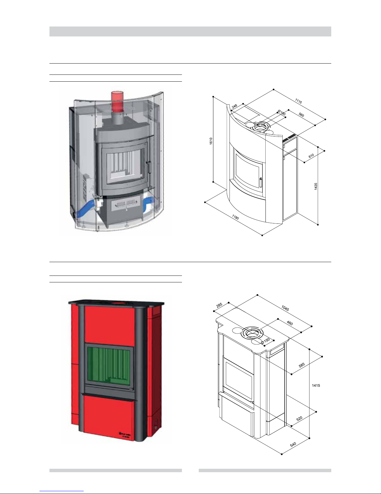
1.4 Dimensions and parts
.........................................................................................................................................................................................................................................
7
1.5 Examples of combined FOGO and FOGHEA with curved or straight front stove clad
.............................................................................................
8
1.6 Burner and pellet hopper parts
.....................................................................................................................................................................................................................
9
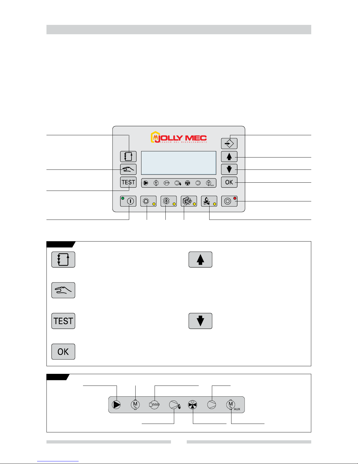
1.7 New-generation simplied electronic controller
...............................................................................................................................................................................
10
1.7.1 Description and use of simplied electronic controller for air heating
............................................................................................................
10
1.7.2 Setting the language
......................................................................................................................................................................................................................
11
1.7.3 Lighting in pellet mode, electronic controller
..................................................................................................................................................................
11
1.7.4 Quick menu
.........................................................................................................................................................................................................................................
13
1.7.5 Output setting for pellet mode
.................................................................................................................................................................................................
14
1.7.6 Room temperature setting for pellet mode
.......................................................................................................................................................................
14
1.7.7 Silencing an alarm
..........................................................................................................................................................................................................................
15
1.7.8 Summer ventilation
.........................................................................................................................................................................................................................
15
1.7.9 Humidier use
....................................................................................................................................................................................................................................
15
1.7.10 Eliminating problems regarding combustion
..................................................................................................................................................................
16
1.7.11 Electronic components test
.......................................................................................................................................................................................................
16
1.7.12 Chronothermostat
............................................................................................................................................................................................................................
17
1.7.13 Lighting in wood mode
.................................................................................................................................................................................................................
19
1.7.14 Service
....................................................................................................................................................................................................................................................
20
1.8 Optimising combustion and damper use
.............................................................................................................................................................................................
21
1.9 Advice and instructions
...................................................................................................................................................................................................................................
22
1.10 Cleaning the stove
.............................................................................................................................................................................................................................................
23
1.11 Parts that can be removed to clean the stove
.................................................................................................................................................................................
24
1.12 Fan removal
...........................................................................................................................................................................................................................................................
25
1.13 Troubleshooting
...................................................................................................................................................................................................................................................
26
1.14 Optionals
..................................................................................................................................................................................................................................................................
29
1.15 Supplementary larger capacity pellet hoppers
.................................................................................................................................................................................
30
1.16 Pellet quality
...........................................................................................................................................................................................................................................................
31
1.17 Use and keeping the installation and maintenance card
..........................................................................................................................................................
32
1.18 Ecological regulation
...............................................................................................................................................................................................................................
33
1.18.1 Waste materials and their disposal
..............................................................................................................................................................................
33
1.18.2 Disposal of the machine
......................................................................................................................................................................................................
33
ASSEMBLY INSTRUCTIONS FOR THE INSTALLER
2.1 Flue
.........................................................................................................................................................................................................................................................
34
2.2 Prearrangement for electrical connections, air intakes and positioning
..........................................................................................................................
35
2.3 Adjusting the feet
.................................................................................................................................................................................................................................................
36
2.4 Foghea air heating stove cladding assembly steps
.......................................................................................................................................................................
36
2.5 Fasi di montaggio rivestimento termostufa Fogo ad aria
..........................................................................................................................................................
38
2.6 Fitting the damper and regulating unit
.................................................................................................................................................................................................
40
2.7 Caldo control
.........................................................................................................................................................................................................................................................
41
2.8 Installing hot air ducting pipes
....................................................................................................................................................................................................................
42
2.9 Example of hot air ducting..........................................................................................................................................................................................................................................................................................43
2.10 Room recycling examples
.............................................................................................................................................................................................................................
44
2.11 Simplied electronic controller wiring diagram
.................................................................................................................................................................................
45