JSTRON A6 Plus User manual


Contents
1. Product description.........................................................................1
1.1 Product statement..........................................................................................1
1.2 Trademarks...................................................................................................1
1.3 Safety instructions.........................................................................................2
1.4 Product accessories......................................................................................3
2. Product overview.............................................................................4
2.1 Product profile..............................................................................................4
2.2 Product characteristics..................................................................................4
2.3 Product model...............................................................................................6
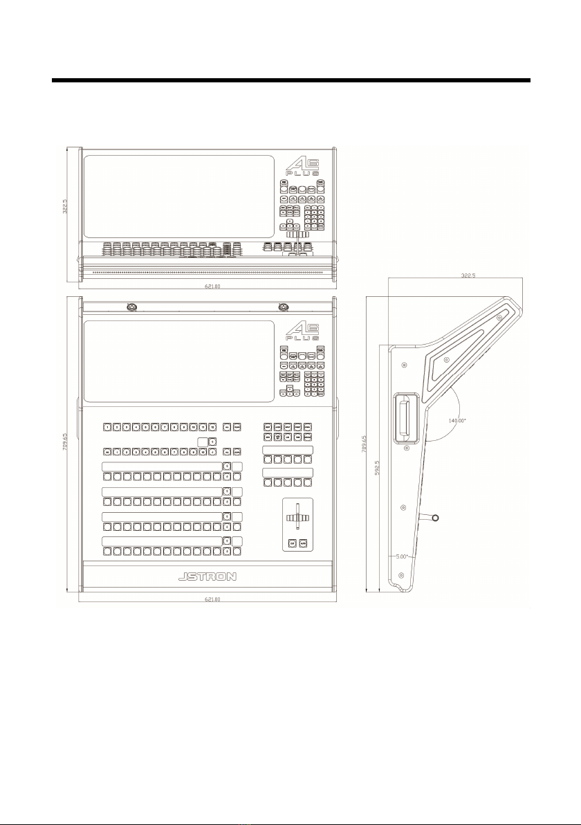
3. Appearance introduction................................................................7
3.1 Product size...................................................................................................7
3.2 Front panel....................................................................................................8
3.2.1 Console lighting.............................................................................8
3.2.2 Touchscreen.......................................................................................8
3.2.3 Destination selection...................................................................8
3.2.4 Layer selection................................................................................9
3.2.5 OLED screen........................................................................................9
3.2.6 User-specified area......................................................................10
3.2.7 Key function..................................................................................10
3.2.8 LED light strip..............................................................................11
3.2.9 Switching area...............................................................................11
3.2.10 Shortcut function area.............................................................12
3.2.11 Numeric keyboard area...............................................................16
3.3 Rear panel...................................................................................................17
3.4 Front panel of master..................................................................................18
3.5 Rear panel of master...................................................................................19
4. Application scenarios ...................................................................20
5. Equipment connection .................................................................21
5.1 Single-machine direct connection ......................................................... …21
5.2 Multi-machine cascading ...................................................................... …21
6. A6plus control software description ...........................................24
6.1 Menu navigation .................................................................................... …24
6.1.1 Master settings..............................................................................25
6.1.2 Input settings................................................................................25
6.1.3 Monitor panel settings................................................................27
6.1.4 Destination settings....................................................................28
6.2 Layer editing...............................................................................................29
6.2.1 Layer area description...............................................................29
6.2.2 Function adjustment......................................................................30
6.2.3 Key..............................................................................................31
6.2.4 Preset.......................................................................................... …33

Contents
6.2.5 Layer shortcut function ......................................................... …33
6.2.6 Switch........................................................................................... …35
6.3 System setting ....................................................................................... …35
6.3.1 Advanced setting ....................................................................... …37
6.3.2 Backup........................................................................................... …37
6.3.3 Hardware ....................................................................................... …37
6.3.4 Update........................................................................................... …38
6.3.5 EN/ Chinese. ................................................................................ …38
7. Case analysis .................................................................................39
8. Troubleshooting ...........................................................................42
9. Warranty .......................................................................................43

Page 1 of 43
Product description
1.1 Product statement
The manual shall not be copied, transcribed or translated in whole or part, or
disclosed commercially in any means (electronic, mechanical, photocopying, recording or
other possible means) or used for any commercial profit without prior written consent
of our company.
Please read this manual carefully before use. Any product specification and
information in the manual are only for reference and subject to improvement without
further notice. Unless otherwise specified, the manual herein is acted as directions to use
only and all statements, information and the like do not constitute the warranty of any kind.
1.2 Trademarks
VESA stands for the trademark of the Video Electronics Standards
Association.
HDMI mark and High-Definition Multimedia Interface are trademarks of HDMI
Licensing LLC.

Page 2 of 43
1.3 Safety instructions
The equipment must be connected with ground wires.
Voltage with rated power shall be employed by the equipment. and the input
voltage error shall be ±10%.
Do not connect AC power line with another AC power line that may cause excessive noise.
Please use the equipment in the environment where the temperature is -10℃ to
45℃ and the relative humidity is 90% or below.
Do not use the equipment in the special environment, such as near heat source
where the equipment may be overheated to damage. Please use the equipment
at the well-ventilated place and keep the air vent smooth.
Do not expose the equipment at the place where the equipment may be collided
accidentally or vibrated and reinforce the equipment in case of the vibration.
Do not put such foreign objects as water and metal objects into the equipment.
Otherwise, the equipment is damaged to cause a fire.
In case of any irregular or exceptional phenomenon, cut off the power supply
instantly, disconnect the AC power line and handle it subject to the
"troubleshooting".
Do not dismantle the equipment by yourself in case of any damage and contact
the designated maintenance center for repair.
The disconnecting device shall remain easily operable.
Pleas confirm that the equipment shall be free from water droplets or splashes
and shall not contain liquid-filled articles such as vases.

Page 3 of 43
1.4 Product accessories
*Above accessories may differ upon service condition of the user.
Project Name Quantity
A6 PLUS
1
Power line
1
Network cable
1
Canon lamp
2
VP(Video
Processor)
1
Power line
2
Manual
1
Conformity
certificate
1

Page 4 of 43
Product overview
2.1 Product profile
A6PLUS seamless switchboard, a video processing device developed for LED
large screen display systems, adopts the industry's top image processing chips and 12-
bit digital image processing to produce real and colorful images. It is mainly used in
the field of on-site stage performance control.
The switchboard is composed of VP (Video Processor) master and console, in
which VP master is responsible for image processing. The console, communicated
with the VP master, is mainly responsible for controlling the master and completing a
series of configurations.
2.2 Product characteristics
18.5-inch full HD (1920*1080) capacitive touchscreen
High precision T-Bar for finer switching
48 user-specified keys and OLED information screens (can be specified as input,
preset, and AUX)
10 shortcut keys and OLED information screen
Key, external mouse, keyboard and touch screen control modes
A single output port can open four screens, with up to 16 screens of image
display, and each screen can be arbitrarily adjusted across the output port,
adjust the size to support seamless switching
Support screen splicing across output ports. The screen is smooth and natural.
There is no tearing, framing or smearing. The splicing can reach
7680*1080/3840*2160 (4K*2K)/1920*4320 resolution output
Up to 24 channels of signal sources can be accessed and 4 channels of LOGO
can be stored
Up to 132 scene switches, supporting scene one-key calling

Page 5 of 43
Available with A8 and A6 400 masters
Pure hardware drive operation, dual power supply configuration, reliable and
stable operation of equipment

Page 6 of 43
2.3 Product model
A6PLUS console
Model
Configuration
A6PLUS Console A6PLUS console and accessories
A6 master
Model Configuration
A6 400-E
Input:
8DVI+2HDMI+2DP
output:
4DVI host +4DVI standby
A6 400-F
Input:
4DVI+2HDMI+2DP+2SDI+2VGA
output:
4DVI host +4DVI standby
A6 400-G
Input:
12DVI+2HDMI+2DP
output:
4DVI host +4DVI standby
A6 400-H
Input:
8DVI+4HDMI+4DP+4SDI+4VGA
output:
4DVI host +4DVI standby
A6 400-I
Input:
4DVI+4HDMI+4DP
output:
4DVI host +4DVI standby
A6 400-M
Input:
8DVI+2SDI+2VGA
output:
4DVI host +4DVI standby
A6 400-N
Input:
4DVI+4HDMI+4DP+2SDI+2VGA
output:
4DVI host +4DVI standby
A6 400-O
Input:
4DVI+6HDMI+6DP+4SDI+4VGA
output:
4DVI host +4DVI standby
A6 400-P
Input:
12DVI+4HDMI+4DP+2SDI+2VGA
output:
4DVI host +4DVI standby
A6 400-Q
Input:
4DVI+6HDMI+6DP+2SDI+2VGA
output:
4DVI host +4DVI standby
A6 master selection
Name Correspondence Instruction
Extended DVI input board
A6 400-DVI 3DVI input
Extended HDMI+DP input
board
A6 400-HDMI DP 2 HDMI+2DP input
Extended VGA+SDI input
board
A6 400-VGA SDI 2 VGA+2SDI input
Extended multi-screen
monitor panel
A6 400-MTB Multi-screen monitoring
process

Page 7 of 43
Appearance introduction
3.1 Product size
Unit: mm

Page 8 of 43
3.2 Front panel
3.2.1 Console lighting
The access to the Canon lights, which can be connected to 2 lights, is controlled by
the back switch of the console.
3.2.2 Touch screen
Single click to control can be carried out through the display screen in the way of
touch control, and reasonable adjustment of menu and parameters can be made at the
same time for real-time monitoring of the preview screen.
3.2.3 Destination selection
Numeric keys 1 to 12 respectively correspond to the destination of the master,
CLEAR: Clear the status of the currently selected destination, CLEAR+ALL:
Clear all destination states.
Key lights are displayed in three different colors. Three different colors also
represent three different states of our keys, black: non-activated, white:
activated, red: selected

Page 9 of 43
Note:
The next level of operation can only be performed when the destination is "red".
The "preview" switching "program" is switched according to the status of the
destination. Only the "activated" and "selected" status can be switched, and the
"inactivated" status cannot be switched.
3.2.4 Layer selection
The destination should be in the "selected" state when a layer is added
Black: no layer White: layer added Red: layer selected
Only the selected layer can be used for input source selection, window
adjustment, and so on
Numeric keys 1 to 10 respectively correspond to 1-10 layers of the master, and
more than 10 pages can be turned down for a total of 4 pages
CLEAR: clear the selected layer, CLEAR+ALL: clear all layers of the current
destination
3.2.5 OLED screen
The OLED screen displays the current key status in real time.

Page 10 of 43
3.2.6 User-specified area
display/function keys
3.2.7 Key function
Under ASSIGN1, four modes, INPUT, PRESET, AUX1 and AUX2 can be
switched, which can be switched by function keys
ASSIGN1, ASSIGN2, ASSIGN3, ASSIGN4, are all keys with different
functions and can be selected freely
The 1 to 12 of INPUT respectively correspond to the input of 1 to 12 ports of
the master, and can turn to the following page after exceeding the input, or can
realize one page displaying 48 input sources by adjusting the function keys
Layer selection is required to select an input source
INPUT key light definition:
The OLED screen does not have a serial number, and the key is black: Panel card
not inserted
The OLED screen has a serial number, and the key is black: current channel has
no input source
The key is white: current channel has input source access
The key is red: current layer is selected, and channel has input source access
The key is dark red: the current layer is selected, and channel has no input source
access

Page 11 of 43
Each of the 1 to 12 keys of PRESET corresponds to a preset, beyond which the
page can be turned down, or 48 presets for one page display can be realized by
adjusting the function keys, with a maximum of 132 presets supported
PRESET key light definition:
The key is black: current channel has no preset
The key is white: current channel already has presets
The key is green: preset templates for the current channel are displayed in
preview
The key is red: preset templates for the current channel are displayed in program
The key is orange: preset templates for the current channel are displayed in
preview and program
The 1 to 12 of AUX respectively correspond to the input of 1 to 12 ports of the
master, and can turn to the following page after exceeding the input, or can
realize one page displaying 48 input sources by adjusting the function keys
The AUX key light definition is the same as that of the INPUT
3.2.8 LED light strip
Concealed light strip can be controlled and adjusted through the system→
advanced setting→ front light
3.2.9 Switching area
Switch progress bar
T-bar: push rod, manually control
switching speed
CUT key: Fast switching
AUTO key: fade in and out. The
time can be set through the menu
switch area.

Page 12 of 43
3.2.10 Shortcut function area
LAYER: layer editing
Select the shortcut function area and then a submenu function
The following functions are for layer editing. Please confirm whether the layer is
selected before setting
D LAYER: with the destination selected, press shortcut to add a D layer
KEY: carry out matting on the selected layer. After pressing the key, the lower
left corner of the menu layer will have matting identification, indicating that
matting has been opened for debugging with the matting area of the menu layer.
Note: the matting can only be done on D layer
FREEZE: the screen is frozen. After pressing the key, there will be a freeze
identification in the lower left corner of the menu layer, indicating that the freeze
has been opened
CLONE: layer cloning
LOCK: layer lock
FULL H: horizontal and full screen of destination
FULL V: vertical and full screen of destination
FULL HV: horizontal and vertical full screen of destination
FULL PORT: output single port full screen
DEST: to be developed
LAYER: layer editing
INPUT: input function
PRSET: Preset function
SCREEN: menu navigation
MVR: monitoring function
USER KEY: to be developed
CUE: to be developed
TIME: to be developed
DEVICE: function debugging

Page 13 of 43
INPUT: input function
Examples of interceptions:
Window source interception is to intercept part of the input source area of the
current window and enlarge the selected area to show the whole window,
X=horizontal start, Y=vertical start, as shown in the following Figure: 8.2.1
As shown in the Figure: 8.2.1
X
HPOS: move to intercept
horizontal position
VPOS: move to intercept vertical
position
HSIZE: intercept screen with
horizontal size.
VSIZE: intercept screen with
vertical size
RESET: reset interception to
default
Example: press HPOS, type the
value through the numeric
keyboard, press Enter to apply,
and the others can be set in this
method
Y
Widt
Heig

Page 14 of 43
PRSET: Preset function
SCREEN: menu navigation
LOCK ALL: lock all presets
UNLOCK ALL: unlock all presets
LOCK UNLOCK: lock/unlock current preset
SAVE PVW: save preview template
SAVE PGM: save program template
OWEITE FROM PVW: preview template
overrides the currently selected preset
OWEITE FROM PGM: program template
overrides the currently selected preset
SAVE PVW TO…: press SAVE PVW
TO… and add the preset numbering key
to manually save the preview template.
If the current numbering template
already exists, it will be directly
overwritten and saved
SAVE PGM TO…: press SAVE PGM
TO… and add the preset numbering key
to manually save the program template.
If the current numbering template
already exists, it will be directly
overwritten and saved
You cannot delete, overwrite, or modify
a template after it has been locked
Control: quickly switch menu page
main menu
Config: quickly switch menu page
to editing page
Setting: quickly switch menu page
to setting page

Page 15 of 43
MVR: monitor calling
DEVICE: Function debugging
VP ID: correspond to the ID
name of the master, multi-
control by one machine, and
monitoring output can be
controlled by switching VP
MODE 4X1: adjust monitor
panel splicing mode to 4HX1V
MODE 2X2: adjust monitor
panel splicing mode to 2HX2V
PAGE1: monitor input page 1
PAGE2: monitor input page 2
PAGE3: monitor input page 3
PAGE4: monitor input page 4
PAGE5: monitor input page 5
The monitor input page can
display 6 input screens.
SAVE SYSTEM: save user
settings
TRANS TIME: reset switching
time to default

Page 16 of 43
3.2.11 Numeric keyboard area
MOD PGM: program output synchronous preview
screen
PANEL LOCK: one-key lock console
FREEZE PGM: this feature is used for A8 masters
BLACK: this feature is used for A8 masters
H&V: horizontal and vertical equal proportion
H POS: horizontal start V POS: vertical start
H SIZE: horizontal size V SIZE: vertical size
For example: the current horizontal window is
960. Press H SIZE after selecting the layer,
enter 1920 with the numeric keyboard, and
press ENTER. The setting is successful.
Numeric keyboard area
ESC COPY PG
FN THRU PG
Up and down, left and right key: HPOS, VPOS, HSIZE
and VSIZE key are cooperated for fine adjustment.
: this feature is used for
A8 masters

Page 17 of 43
3.3 Rear panel
1. Aviation connector network cable interface
LAN1: connect to console master
LAN2: function yet to be developed
2. USB interface
5V power supply, external equipment such as console can be upgraded with
mouse, keyboard and USB flash drive, and 4 ports can be plugged and played.
3. RS232 bus interface (DEBUG)
Equipment debugging interface
4. Power interface
Equipment supply
5. Console power supply switch (PWR)
6. Lamp switch (LAMP)
Table of contents