JUKA VD75G User manual


2
1. General Information . . . . . . . . . . . . . . . . . . . . . . . . . . . . 4
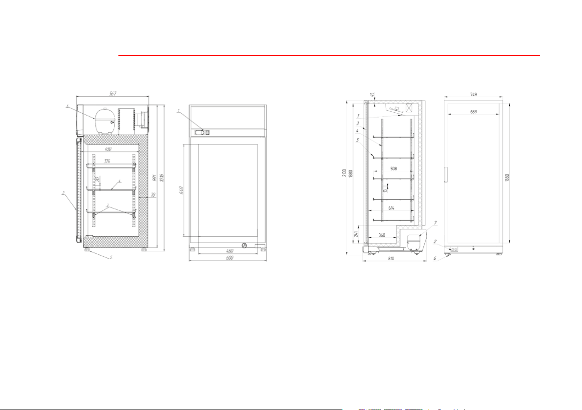
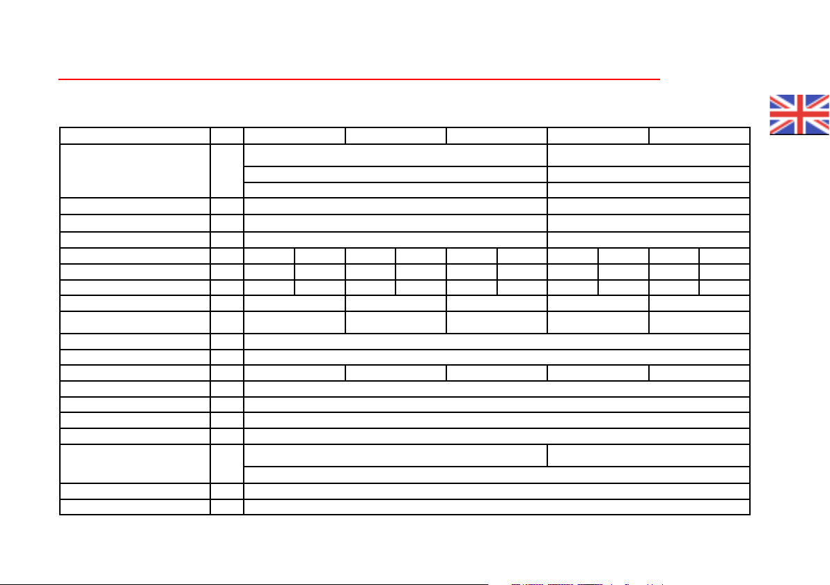
2. Technical Characteristics . . . . . . . . . . . . . . . . . . . . . . . . . .9
3. Transportation, Installation and Startup . . . . . . . . . . . . . . . . 12
3.1. Transportation. . . . . . . . . . . . . . . . . . . . . . . . . . . . . . 12
3.2. Storage of the Equipment. . . . . . . . . . . . . . . . . . . . . . . . 12
3.3. Requirements to the Place of Operation . . . . . . . . . . . . . . . 12
3.4. Installation . . . . . . . . . . . . . . . . . . . . . . . . . . . . . . . . 12
3.5. Connecting Electricity and Startup . . . . . . . . . . . . . . . . . . 13
4. Operation . . . . . . . . . . . . . . . . . . . . . . . . . . . . . . . . . 14
4.1. Operation Requirements . . . . . . . . . . . . . . . . . . . . . . . . 14
4.2. Temperature Settings . . . . . . . . . . . . . . . . . . . . . . . . . . 15
4.3. Electronic controller CAREL . . . . . . . . . . . . . . . . . . . . . 15
4.3.1. Light Signals on the Electronic Controller`s Display . . . . . . . 15
4.3.2. Setting of the Temperature . . . . . . . . . . . . . . . . . . . . . . 15
4.3.3. Additional Defrosting . . . . . . . . . . . . . . . . . . . . . . . . 15
4.3.4. Warning Signals . . . . . . . . . . . . . . . . . . . . . . . . . . . . 15
4.4. Electronic controller EVCO . . . . . . . . . . . . . . . . . . . . . . 16
4.4.1. Light Signals on the Electronic Controller`s Display . . . . . . . 16
4.4.2. Setting of the Temperature . . . . . . . . . . . . . . . . . . . . . . 16
4.4.3. Warning Signals . . . . . . . . . . . . . . . . . . . . . . . . . . . . 16
4.5. Electronic controller Dixell. . . . . . . . . . . . . . . . . . . . . . . 17
4.5.1. Display . . . . . . . . . . . . . . . . . . . . . . . . . . . . . . . . . 17
4.5.2. Checking the set temperature . . . . . . . . . . . . . . . . . . . . 17
4.5.3. Changing the temperature.. . . . . . . . . . . . . . . . . . . . . . 17
4.5.4. Manual defrost request . . . . . . . . . . . . . . . . . . . . . . . . 17
4.5.5. List of alarms . . . . . . . . . . . . . . . . . . . . . . . . . . . . . 17
5. Maintenance . . . . . . . . . . . . . . . . . . . . . . . . . . . . . . . . 18
5.1. Cleaning and Maintenance. . . . . . . . . . . . . . . . . . . . . . . 18
5.1.1. Cabinet Cleaning . . . . . . . . . . . . . . . . . . . . . . . . . . . 18
5.1.2. Defrosting of the Evaporator. . . . . . . . . . . . . . . . . . . . . 18
5.1.3. Condenser Maintenance . . . . . . . . . . . . . . . . . . . . . . . 18
5.1.4. Door Seal. . . . . . . . . . . . . . . . . . . . . . . . . . . . . . . . 19
5.1.5. Other Terms and Conditions . . . . . . . . . . . . . . . . . . . . 19
6. Fault Identication and Repair. . . . . . . . . . . . . . . . . . . . . . 19
7. Disposal of Equipment . . . . . . . . . . . . . . . . . . . . . . . . . . 20
COOLING AND FREEZING UPRIGHT CABINETS INSTRUCTION MANUAL
Dear customers! Please read this manual thoroughly before operating the equipment!
Following our instructions, you will ensure long and eective performance of the equipment.
Content

3
Dear customers! If you purchased our equipment on R290 refrigerant, please read carefully the instruction manual of the freezer.
Special precautionary instruction for equipment with refrigerant R290.
Fluorinated greenhouse gases are in a hermetically sealed system. Any kind of works connected with refrigeration or electric systems
shall be carried out by authorized service. ere is no warranty responsibility for the repair by unauthorized persons.
• is equipment contains ammable and explosive refrigerant propane R290!
• Be sure to maintain a minimum distance of 10 cm from the walls of the equipment to the walls and surrounding objects. Make sure to
provide proper air circulation for the equipment with combustible refrigerant!
• Do not close air inlets on the body frame of the equipment.
• Disconnect equipment from voltage before any maintenance operation.
• Any kind of works connected with refrigeration or electric systems shall be carried out by authorized service and personnel
• It is allowed to open refrigerant circulation circuit and pump it down only in well-ventilated areas or outside. Make sure that there are
no people or animals around.
• Correct disposal of refrigerant propane R290 is a must!
PRECAUTIONS
• Make sure not to damage the refrigerant circulation circuit!
• Do not use mechanical or other means to accelerate defrosting process other than those authorized by the manufacturer.
• It is prohibited to put heating appliances inside the freezer.
e manufacturer reserves the right to modify product design for its performance improvement without prior notication of the
customer. Product images are for illustrative purposes only and may dier from the actual product.

4
1. GENERAL INFORMATION
JUKA Upright Cabinets belong to professional cooling and freezing equipment and are designed for presentation, sales, and storage of
refrigerated or frozen foodstu in stores, supermarkets, pastries, cafes, and other catering establishments. Upright cabinets preserve the
quality, safety, and taste of food. Operation temperature ranges inside JUKA Upright Cabinets:
Cooling Upright Cabinets:
VD75G, VD70M +1ºC / +10ºC and SD70M +5ºC / -5ºC at ambient temperature +16ºC / +35ºC and relative humidity up to 75%;
VD75GA +1ºC / +10ºC at ambient temperature +16ºC / +30ºC and relative humidity up to 55%;
VG60G +2ºC / +10ºC and VD60G 0ºC / +8ºC at ambient temperature +16ºC / +25ºC and relative humidity up to 60%.
Freezing Upright Cabinets:
ND75G, ND70M -12ºC / -22ºC at ambient temperature +16ºC / +35ºC and relative humidity up to 75%.
NG60G -12ºC / -22ºC at ambient temperature +16ºC / +30ºC and relative humidity up to 55%.
ND60G -14ºC / -22ºC at ambient temperature +16ºC / +25ºC and relative humidity up to 60%.
Upright cabinets are equipped with a built-in compressor, which is located at the top (SD70M, VD70M, ND70M, NG60G) and in the
bottom (VD75G, ND75G, VD75GA, VD60G, VG60G, ND60G) part of a cabinet.
Cooling inside the cabinet is based on a system of dynamic airow (models SD70M, VD70M, ND70M, VD75G, ND75G, VD75GA,
VD60G, ND60G) or static cooling (NG60G, VG60G). Depending on the type of the upright cabinet, there are solid door and glass door
units.
Depending on the model, upright cabinets have 2, 3, 4, 5 or 10 adjustable grid shelves.
JUKA upright cabinets are manufactured following the latest technologies and comply with such standards as ІЕС 60335-2-89, IEC
60335-1, IEC 61000-6-3, IEC 61000-6-1.
Fluorinated greenhouse gases are in a hermetically sealed system.
Equipment can be lled with refrigerant R290 (GWP 3), R600a (GWP 3), R404a (GWP 3922) or R452a (GWP 2140). Molecular
formula of refrigerant R290 - C3H8. Molecular formula of refrigerant R600a - С4Н10. Molecular formula of refrigerant R404a - CHF2CF3.
Molecular formula of refrigerant R452a - CHF2CF3+CH2F2+C3H2F4.

5
Picture 2. Upright Cabinet SD70M, VD70M, ND70M
1. Electronic controller (temperature control).
2. Cabinet control panel (switches).
3. Cabinet door.
4. Shelf support.
5. Grid shelf
6. Levelling supports.
7. Compressor department.
Picture 1. Upright Cabinet VD75G, ND75G
1. Electronic controller (temperature control).
2. Cabinet control panel (switches).
3. Cabinet door.
4. Shelf support.
5. Grid shelf
6. Levelling supports.
7. Compressor department.
Elements of the Construction:

6
Picture 4. Upright Cabinet VD75GA
1. Electronic controller (temperature control).
2. Cabinet control panel (switches).
3. Cabinet door.
4. Shelf support.
5. Grid shelf
6. Levelling supports.
7. Compressor department.
Picture 3. Upright Cabinet NG60G
1. Cabinet control panel (temperature control/switches).
2. Cabinet door.
3. Shelf support.
4. Grid shelf
5. Levelling supports.
6. Compressor department.

7
Picture 6. Upright Cabinet VD60G
1. Electronic controller (temperature control).
2. Cabinet control panel (switches).
3. Cabinet door.
4. Shelf support.
5. Grid shelf
6. Levelling supports.
7. Compressor department.
Picture 5. Upright Cabinet VG60G
1. Electronic controller (temperature control).
2. Cabinet control panel (switches).
3. Cabinet door.
4. Shelf support.
5. Grid shelf
6. Levelling supports.
7. Compressor department.

8
Picture 7. Upright Cabinet ND60G
1. Cabinet control panel (switches).
2. Cabinet door.
3. Shelf support.
4. Grid shelf
5. Levelling supports.
6. Compressor department.
Picture 8. Upright Cabinet VD140M, ND140M
1. Cabinet control panel (switches).
2. Cabinet door.
3. Shelf support.
4. Grid shelf
5. Levelling supports.
6. Compressor department.

9
2. TECHNICAL CHARACTERISTICS
Technical parameters Unit. SD70M VD70M ND70M VD140M ND140M
Dimensions:
Height
mm
2075 2075
Width 700 1412
Depth 890 892
Gross volume dm3563 1284
Net volume dm3460 920
Upright cabinet net weight kg 121 180
Refrigerant type - R452a R404a R452a R404a R452a R404a R452a R404a R452a R404a
Refrigerant quantity kg 0,27 0,27 0,27 0,27 0,27 0,27 0,55 0,55 0,5 0,5
CO2 EQ t 0,58 1,06 0,58 1,06 0,58 1,06 1,18 2,16 1,07 1,96
Current consumption А 3,2 2,5 3,3 4,3 3,4
Electric power consumption kW\
24h 6,0 3,0 8,5 4,8 13,9
Climate class 7
Ambient temperature range °С +16 ÷ +35
Operating temperature range °С -5 ÷ +5 +1 ÷+10 -12 ÷ -22 +1 ÷ +10 -12 ÷ -22
Voltage and current frequency V/ Hz 220-240/50
Temperature controller - electronic controller
Type of air movement dynamic
Defrosting type automatic
Basic delivery set:
grid shelves pcs 5 10
lock +
ickness of isolation mm 70
Max. load on a grid shelf kg 30

10
Technical parameters Unit. VD75G ND75G VD75GA
Dimensions:
Height
mm
2035 2035 2100
Width 750 750 749
Depth 820 820 810
Gross volume dm3590 590 749
Net volume dm3490 490 700
Upright cabinet net weight kg 154 154 152
Refrigerant type - R452a R404a R452a R404a R290 R290
Refrigerant quantity kg 0,27 0,27 0,27 0,27 0,12 0,05
CO2 EQ t 0,58 1,06 0,58 1,06 0,00 0,00
Current consumption А 2,5 3,6 3,3 2,3
Electric power consumption kW\
24h 6,0 10,0 11,0 3,52
Climate class 7 4
Ambient temperature range °С +16 ÷ +35 +16 ÷ +30
Operating temperature range °С +1 ÷ +10 -12 ÷ -22 +1 ÷ +10
Voltage and current frequency V/ Hz 220-240/50
Temperature controller - electronic controller
Type of air movement dynamic
Defrosting type automatic
Basic delivery set:
grid shelves pcs 4 5
lock - +
ickness of isolation mm 60 45
Max. load on a grid shelf kg 25 57

11
Technical parameters Unit. VG60G VD60G ND60G NG60G
Dimensions:
Height mm
860 1016
Width 599 600
Depth 591 567
Gross volume dm3126 115
Net volume dm3102 99 105
Upright cabinet net weight kg 52 52
Refrigerant type - R600a R290 R452a R404a R290
Refrigerant quantity kg 0,037 0,043 0,043 0,15 0,15 0,065
CO2 EQ t 0,00 0,00 0,00 0,32 0,59 0,00
Current consumption А 0,7 0,8 1 1,94 1,94 1,6
Electric power consumption kW\24h 1,6 2,2 4,0 6,0 6,0 4,9
Climate class 3 4
Ambient temperature range °С +16 ÷ +25 +16 ÷ +30
Operating temperature range °С +2 ÷ +10 0 ÷ +8 -14 ÷ -22 -12 ÷ -22
Voltage and current frequency V/ Hz 220-240/50
Temperature controller - electromechanical electronic controller
Type of air movement gravitational dynamic gravitational
Defrosting type automatic manual
Basic delivery set:
grid shelves pcs 2 3
lock -
ickness of isolation mm 50 70
Max. load on a grid shelf kg 16 20

12
3. TRANSPORTATION, INSTALLATION AND STARTUP
3.1. Transportation
It is forbidden to transport the equipment in any position other than vertical. During transportation, the equipment must be properly
secured and packed to prevent any movement or impact inside the vehicle, protected from the weather (direct sunlight, rain, snow, etc.).
Manufacturer supplies upright cabinets protected by cardboard corners and lm.
ATTENTION! It is forbidden to connect upright cabinets to the power supply within at least 2 hours aer it has been transported
and installed.
3.2. Storage of the Equipment
Upright cabinets should be stored vertically. It is forbidden to store units under direct sunlight or inuence any other atmospheric
phenomena.
3.3. Requirements to the Place of Operation
It is necessary to install the upright cabinet in a dry, ventilated room at the distance no less than 10 cm away from the nearest wall. ere
should be good airow around the compressor unit. It is also necessary to install an upright cabinet away from any equipment source of heat
and conditioners/ventilators.
e upright cabinet should be installed away from direct sunlight or any other atmospheric phenomena. Make sure that voltage and
frequency in the electricity grid correspond to those recommended by the manufacturer.
3.4. Installation
• Unpack the unit, remove the protective lm and cardboard corners;
• Install the unit on a solid surface and adjust the horizontal position of the cabinet with the levelling supports.
ATTENTION! Make sure to install the upright cabinet with the inclination of min. 20° degrees to the rear side.
e cabinet is supplied to the buyer partially disassembled. Aer transportation and installation of the unit, please follow the next steps:
• I. Fix shelf holders in perforated rack straps.
• II. Place the grid shelves on the xed holders.
e rst cleaning of the unit should be done aer unpacking and/or its rst launching. For cleaning use only warm water (no more than
40°C) with neutral detergents. Do not use any cleaning agents that contain chlorine and sodium of dierent types as they can damage the
protective layer and components of the unit. Any residue of adhesive or silicone on metal elements of the equipment should be removed only
with extraction gasoline (it is not applied to plastic elements!). Do not use any other organic solvents!
ATTENTION! Upright cabinet shall not be cleaned with a water jet, use only a damp cloth. Aer transporting and installation
of the equipment, wait for about 2 hours before its launching.
ATTENTION! Make sure not to damage the refrigerant circulation circuit!

13
Picture 10. Cabinet control panel, Model VD75GA
1. Main switch (turns on / o the unit).
2. Lighting switch;
3. Electronic control panel (temperature control is
located on a top panel inside the cabinet).
Picture 11. Cabinet control panel, Models
NG60G, ND60G, VD60G
1. Electronic control panel (temperature
control);
2. Lighting switch;
3. Main switch (turns on/o the unit).
Picture 9. Cabinet control panel, Models
VD75G, ND75G
1. Electronic control panel
(temperature control);
2. Lighting switch ;
3. Main switch (turns on / o the unit).
3.5. Connecting Electricity and Startup
e device should be connected to a separate, properly mounted electrical circuit with a grounding socket.
e system of the power supply must be maintained with automatic circuit breakers.
ATTENTION! Strongly avoid connecting through extension cords!
• When the plug is connected directly into the socket, you have to:
• Turn on the main switch
• Set on the temperature on the electronic controller`s display (except for Model VD60G where the temperature is regulated by the
electromechanical thermostat)
• Turn on the lighting switch (if your model is equipped with internal lighting).

14
Picture 12. Cabinet control panel, Models
SD70M, VD70M, ND70M, VD140M,
ND140M
1. Electronic control panel (temperature
control);
2. Main switch (turns on / o the unit).
4. OPERATION
4.1. Operation Requirements
e temperature inside the refrigerated compartment of the cabinet and its operation cycles may vary due to dierent reasons (such as
the temperature of refrigerated foodstu, the ambient temperature in the premises, door opening frequency, etc.).
Upright cabinets are designed for operation only in the particular climate class! The manufacturer is not responsible for
the normal operation of the unit in the climate class, other than specified in the technical characteristics (indicated on the
data plate).
• To ensure proper and long-lasting operation of JUKA Upright Cabinets, please follow the recommendations indicated below:
• Aer transporting the equipment, wait for about 2 hours before its launching
• e counter should be installed away from direct sunlight
• Before stocking the unit with refrigerated products, wait until the desired temperature is reached
• Do not place warm or hot products inside the upright cabinet
• Do not store beverages in bottles and cans, especially carbonated beverages, in the freezer chamber. e cans and the bottles may
explode.
• Do not store explosive substances, such as ammable aerosol cans, inside the unit
• During the day it is not allowed to place more products in the chamber of the unit than its freezing capacity can handle
• To ensure proper storage conditions, please avoid full loading of the grid shelves
• To prevent the packaging from freezing, dry it thoroughly before placing it in the appliance.
• Do not block the ventilation openings inside the freezer as it may prevent your appliance from functioning properly.
• Keep the condenser clean. e buyer should periodically perform technical maintenance to avoid malfunctions and/or unsatisfying
operations of the cabinet.
• Aer closing the doors, do not try to use force to open them. e cooling of the gas causes a reduction in pressure inside the freezer, resulting
in a partial vacuum that makes the door more dicult to open. In 1 – 2 minutes pressure equalizes and the door becomes easier to open.
• Please avoid unnecessary openings of the door, as well as do not leave the door open for a long time.
Picture 13. Cabinet control panel,
Model VG60G
1. Lighting switch;
2. Main switch (turns on/o the unit).

15
4.2. Temperature Settings
Controller is a device used to set and maintain a desired temperature inside the upright cabinet. e manufacturer sets all necessary
settings of the electronic controller for the normal operation of the unit. Before start-up, the buyer should check and, if needed, set the
temperature on the electronic controller display. e display of the electronic controller shows the actual temperature inside the equipment.
ATTENTION! Do not interfere with the system parameters of the electronic controller as it may cause serious consequences and
can lead to failure of the equipment.
4.3. Electronic controller CAREL
4.3.1. Light signals on the electronic controller`s display:
Diode а - Compressor: e symbol is visible during operation of the compressor. It
is blinking when compressor start is delayed by security procedure.
Diode b - Fan:the symbol is visible when the fans are on. It is blinking when the fan
start is delayed by an external disengagement or when another procedure is in progress.
Diode c – Defrosting:the symbol is visible when the defrosting function is turned
on. It is blinking when defrosting start is delayed by external disengagement or
when another procedure is in progress.
Diode d – Alarm:the symbol is visible when the alarm is activated.
Diode e - the temperature inside the equipment is displayed.
4.3.2. Setting of the Temperature
To change the settings of the temperature you have to:
1. Push the button 2- the screen will show “SET”; hold for 1 second and blinking temperature value will be displayed;
2. Increase or decrease the temperature by pressing buttons 1 or 3;
3. Push the button 2again, to set a new temperature.
4.3.3. Additional Defrosting
e device operates in the mode of automatic defrosting in 5-6 hours interval. If you noticed incomplete defrosting, complete the manual
defrost. If you notice an incomplete defrost, then manual defrost must be performed, by pressing button 3and holding it for 3 seconds (a
defrost symbol will appear on the display). e system will automatically nish defrosting of the evaporator and continue its operation.
4.3.4. Warning Signals:
„E0” - malfunction of temperature sensor
„E1” - malfunction of defrost sensor
„cht”- warning signal indicating that condenser is dirt
„CHt”- alarm of a dirty condenser.
Picture 14. Electronic controller CAREL

16
4.4. Electronic controller EVCO
4.4.1. Light Signals on the Electronic Controller`s Display:
Diode а – Compressor: e symbol is visible during operation of
the compressor. It is blinking when modication process is ongoing or
in case when compressor operation is protected by security procedure.
Diode b – Defrosting: the symbol is visible when the defrosting
function is turned on. It is blinking when defrosting start is delayed
by external disengagement or when another procedure is in progress.
Diode c – Celsius temperature scale. e symbol is visible when
temperature is set in degrees Celsuis.
Diode d – Fahrenheit temperature scale. e symbol is visible when temperature is set in degrees Fahrenheit.
Diode f – temperature inside the cabinet.
During operation the display of the controller shows the actual temperature inside the equipment.
• Locking/unlocking of the controller keypad
e controller keypad is automatically locked in 30 seconds aer the last pressure of the button - the «Loc» code is displayed for 1
second. To unlock press any button while holding it for 4 seconds - «UnL» code will be displayed for 4 seconds.
• Turning on/o of the equipment
Ensure that the keypad is not locked, unlock if necessary. To turn the equipment on/o press the button and hold for 4 seconds -
the indicator will blink, aer this the equipment will be switched on / o.
When voltage is supplied, the red switch must light up (switch is equipped with light diodes, so when the voltage is supplied, it must light up).
4.4.2. Setting of the Temperature
• make sure the keypad is not locked, unlock if necessary
• briey press the button , indicator ( ) will start to blink;
• using the buttons and set the required tempera;
• briey press the button to conrm or do nothing within 15 seconds - the indicator ( ) will stop blinking, the controller
completes the setup process (all changes will be saved).
4.4.3. Warning Signals
„Pr1” - malfunction of temperature sensor
„Pr2” - malfunction of defrost sensor
„СOH”- warning signal indicating that condenser is dirt and overheated;
„dFd”- defrosting process is nished.
Picture 15. Electronic controller EVCO

17
4.5. Electronic controller Dixell
4.5.1. Display
1. Defrost;
2.Compressor operation;
3. Evaporator fan operation (in some models it signals condenser fan operation)
4. Temperature display.
e blinking indicator value indicates a program delay.
4.5.2. Checking the set temperature.
• Press the SET key (8) for a moment, then the set temperature will be shown on
the display;
• Press the SET key (8) briey, or wait 5 seconds to return to the normal display.
4.5.3. Changing the temperature. To change the set values:
• Press the SET key(8) for more than 2 seconds. e set temperature value will be displayed and the «°C» or «°F» indication will blink;
• To change the temperature, press the keys (5) and (6) for 10 seconds;
• To conrm the new value, press SET (8) or do not press the keys for 10 seconds.
4.5.4. Manual defrost request (if provided by the manufacturer).
• Press the key (7) for more than 3 seconds, then the defrost will start, which is signaled by the indication.
4.5.5. List of alarms.
dA - open doors alarm: When the door is opened, the controller starts counting down the time, blocking the operation of the air cooler
fan. Aer this time expires, the alarm is started and the «dA», signal is blinking on the display, during which the fan operation is restored.
e alarm is reset automatically, when the doors are closed.
P1 - chamber temperature sensor failure; P2 - evaporator temperature sensor failure;
HA - high temperature in the chamber: indicates too high temperature in the chamber and may indicate equipment malfunction. e
alarm turns o automatically, when it returns to normal operation.
LA - low temperature in the chamber: indicates too low temperature in the chamber and may indicate an equipment malfunction. e
alarm turns o automatically when returning to normal operation.
ATTENTION! Failure to comply with the recommendations regarding connection and operation of the equipment will void the
warranty.
e manufacturer reserves the right to modify product design for its performance improvement without prior notication of the
customer. Product images are for illustrative purposes only and may dier from the actual product.
Picture 16 Electronic controller Dixell electronic controller

18
5. MAINTENANCE
5.1. Cleaning and Maintenance
ATTENTION! All maintenance services should be carried out aer the device is disconnected from the voltage!
Make sure not to damage the temperature controller and other electric parts during the cleaning and maintenance of the unit.
It is recommended to switch o the unit at least once a month to conduct internal cleaning, condenser maintenance, defrosting
procedures and check the door seals.
5.1.1. Cabinet Cleaning
During the cleaning of the upright cabinet, please AVOID TO USE the following objects:
• any sharp objects for cleaning of the surfaces;
• any mechanical objects to speed up the process of defrosting;
• appliance shall not be cleaned with a water jet, use a damp cloth.
5.1.2. Defrosting of the Evaporator
e upright cabinet is equipped with a system of automatic defrosting of the evaporator -
with an interval of 8 hours. In the case of incomplete defrosting, this should be done manually.
5.1.3. Condenser Maintenance
e user should periodically check the condition of the condenser. e ingoing and outgoing
air openings of the condenser must not be blocked by objects. A dirty condenser leads to reduced
cooling capacity, overheating of the refrigeration unit and even damage to the compressor.
ATTENTION! e condenser needs to be cleaned at least once a month.
Clean the condenser ns with a so brush or paintbrush. To do that:
1) Disconnect the device from the power source;
2) Remove the protective grill covering the unit;
3) Using a so brush, clean the condenser from dust, remnants of the package, etc. (Pic. 16);
4) Aer cleaning, place the protective grill in reverse order.
In case of dirty condenser (dust between the condenser ns) it is recommended to use an air compressor or compressed nitrogen to
blow out the contaminants between the ns.
e compressor is equipped with an internal backup (thermal) switch, which protects the engine from accidental overloads. If you hear unnatural,
loud operation or the heavy start of the compressor, switch o the appliance, check the condition of the condenser (in case of pollution - clean it).
WARNING! Failure to perform this service can result in a complicated starting of the compressor, the operation of the unit, the
overheating of the compressor and, consequently, deterioration of the cooling eciency.
e manufacturer is not responsible for damage to the unit that arose as a result of noncompliance with the purity of the condenser!
Picture 17. Cleaning the condenser

19
5.1.4. Door Seal
e door seal should be cleaned regularly with clean water without detergents, and then wiped dry with a so cloth. Please make sure
that the cabinet door close properly aer cleaning. To check the state of the door seal place a sheet of paper between the seal and the cabinet
body and close the door. When you try to pull out the paper, you should feel moderate resistance.
5.1.5. Other Terms and Conditions
Metal parts of the equipment can corrode in case of improper use and maintenance. To prevent corrosion of the metal parts, please:
• Do not use any cleaning agents that contain chlorine and sodium of dierent types as they can damage the protective layer and parts of
the unit (including dierent types of stainless steel).
• During cleaning and maintenance of the equipment, please make sure not to damage the data plate of the unit. e data plate contains
useful product-specic data.
6. FAULT IDENTIFICATION AND REPAIR
In case of any problems during the startup of the equipment or its operation, it is necessary to return to those sections of the service
manual that explain their operations. is aims to ensure that the device is properly operated. If you still experience diculties, the following
hints will help you solve the problem.
e equipment does not work:
Make sure that:
• e device is connected to an electrical power supply
• Voltage and frequency in the network corresponds to those recommended by the manufacturer 220 V / 50 Hz
• e main switch is turned on
• e controller is switched on
Water leakage under the device or into the chamber:
Make sure that:
• Verify the correctness of device levelling
• Verify the patency of outlet hoses
• Empty the condensate tray or container
Damage to the power cord:
• In case of damage to the power cord in order to avoid danger its replacement must be carried out by a manufacturer, service department
or similarly qualied personnel. In case of power cord replacement by unauthorized persons WARRANTY CAN BE VOIDED!
e device is operating, the lighting is switched o...
Make sure that:

20
• e lighting switch is on
• Fluorescent lamp or the starter of the device are not burnt
Equipment does not reach the appropriate temperature, the lighting is on:
Make sure that:
• e main switch is turned on
• e temperature setting on the controller is set correctly
• e controller is operating properly
• e condenser is not lthy, and clean it when necessary
• e ambient temperature does not exceed 35 °
• Enough time has passed for products to be cooled
• e cabinet does not have too many products and does not exceed the maximum freezing capacity
• e door hardware closes correctly and the sealant is adjacent to the hardware case
• Check that the ventilation openings are not blocked
• Check whether the evaporator is not ooded. If necessary, complete preventive defrosting of equipment, pre-shiing the products to
another location with the appropriate mode.
e equipment is working too loud:
Make sure that:
• e device is standing stably and is properly levelled
• Furniture adjoining the device do not vibrate when the compressor is working
• Internal elements have been properly mounted
Dirty condenser alarms (cht, CHt):
cht - pre-alarm indicating that condenser is dirt. cht is shown on the display, alternating with the current temperature while cabinet
operates normally. e alarm will be reset when temperature is normalized.
CHt - dirty condenser alarm. Alarm indicates that condenser is dirty and the condenser temperature is high. CHt switch o the compressor
and switch on the alarm (to reset the alarm press «SET»). CHt is shown on the display, alternating with cht and the current temperature.
WARNING! e “CHt” alarm can only be reset manually by switching the unit o (on power-up, if the temperature is still above
the normal, the alarm will go on again).
dor - door alarm. When the door is opened, the controller will start counting the pre-alarm time and block operation of the ventilator.
When time is over, the alarm will be activated immediately and the display will show “dor” alternating with the temperature reading.
Ventilator resumes its operation. e alarm will be reset when the door is closed.
(«CAREL» controller only) Signs E0/E1/L0/HI/EE/Ed/DF on the electronic controller`s display:
This manual suits for next models
11
Table of contents