JUNO HF3434D User manual

SERVICE MANUAL
Model HF3434D

CONTENTS
SERVICE ACCESS
FACE PLATE UNIT ............................................................................................................1
BACK COVER UNIT ..........................................................................................................2
FRONT COVER UNIT .......................................................................................................3
SIDE COVER UNIT ...........................................................................................................4
MACHINE BASE ................................................................................................................5
MECHANICAL ADJUSTMENT
MACHINE SOCKET...........................................................................................................6
NEEDLE BAR HEIGHT......................................................................................................7
PRESSER BAR HEIGHT ...................................................................................................8
FEED DOG HEIGHT..........................................................................................................9
TIMING OF THE NEEDLE AND THE FEED DOG ............................................................10
TIMING OF THE NEEDLE AND THE UPPER KNIFE .......................................................11
HEIGHT OF THE LOWER LOOPER .................................................................................12
CLEARANCE BETWEEN THE NEEDLES AND THE LOWER LOOPER
/NEEDLE GUARDS ...................................................................................................13-15
CLEARANCE BETWEEN THE NEEDLES
AND THE FIXED NEEDLE GUARD .........................................................................16
POSITION OF THE CHAINING FINGER ..........................................................................17
POSITION OF THE UPPER LOOPER ..............................................................................18
TIMING OF THE NEEDLE AND THE LOWER LOOPER ..................................................19
TIMING OF THE UPPER AND LOWER LOOPERS ..........................................................20
CLEARANCE BETWEEN THE LOOPERS........................................................................21
CLEARANCE BETWEEN THE NEEDLE AND THE UPPER LOOPER.............................22
POSITION OF THE KNIVES .............................................................................................23
POSITION OF THE LOWER LOOPER THREAD GUIDE .................................................24
STITCH LENGTH ..............................................................................................................25
THREAD TENSION DIALS ................................................................................................26
PLAY OF MAIN SHAFT .....................................................................................................27
BELT TENSION .................................................................................................................28
OILING ........................................................................................................................... 29
GAUGES FOR SERVICING .......................................................................................... 30
PARTS LIST .................................................................................................................. 31-50

1
MODEL 3434D
FACE PLATE UNIT
To remove:
1. Loosen the set screw A and remove the face plate unit.
To attach:
2. Fit the U-groove of the face plate between the setscrew A and set plate, put the rib of face
plate into the front cover unit and back cover unit and tighten the setscrew.
Setscrew A
Face plate unit
U-groove
Set plate
Back cover unit
Rib
Front cover unit
SERVICE ACCESS

2
MODEL 3434D
BACK COVER UNIT
To remove:
1. Remove setscrews A and the spool stand.
2. Remove setscrews B,C and D.
3. Remove the back cover unit.
To attach:
4. Put the ribs of back cover into the front cover unit and tighten setscrews B, C and D.
5. Attach the spool stand with setscrew A.
Back cover unit
Setscrew B
Setscrew C
Setscrew A
Setscrew D
Rib
Rib
Spool stand
SERVICE ACCESS

3
MODEL 3434D
FRONT COVER UNIT
To remove:
1. Remove setscrews A and the looper cover unit.
2. Remove the face plate unit and the back cover unit.
3. Turn the hand wheel toward you with your hand, and set the upper looper at lowest position,
and remove setscrews B, C, D,E and the front cover unit.
To attach:
4. Attach the front cover unit with setscrews B, C, D and E.
5. Attach the looper cover unit with setscrew A.
6. Attach the back cover unit and face plate unit.
Setscrew C
Setscrew D
Upper looper should be set
at lowest position
Front cover unit
Looper cover unit
Setscrew A
Setscrew E
Setscrew B
SERVICE ACCESS

4
MODEL 3434D
SIDE COVER UNIT
To remove:
1. Open the side cover unit. Remove the snap ring E-3 and pull out the shaft.
To attach:
2. Attach the side cover unit and insert the shaft and attach the snap ring.
Side cover unit
Snap ring E-3
Shaft
SERVICE ACCESS

5
MODEL 3434D
MACHINE BASE
To remove:
1. Remove setscrews A, B, C, D and two hinge screws E, and remove two base cushions F
and washers.
2. Remove the machine base.
NOTE: Do not remove the remaining two base cushions.
To attach:
3. Attach the machine base unit, and tighten setscrews A, B, C and D.
4. Attach the two base cushions F, washers, and tighten hinge screws E.
Washer (thick)
Washer
Base
cushion F
Hinge screw E
Setscrew D
Setscrew C Setscrew B
Machine base
Setscrew A
Washer (thin)
SERVICE ACCESS

6
MODEL 3434D
MACHINE SOCKET
To remove:
1. Remove the back cover unit.
2. Remove the setscrews (A, B) and the machine socket unit from the motor fixing plate.
3. Remove the two setscrews C, and pull out the cord connectors.
To attach:
4. Insert the cord connectors as shown below.
5. Attach the machine socket, and tighten the two setscrews C.
6. Attach the machine socket unit on the motor fixing plate and tighten the setscrews (A, B).
7. Attach the back cover unit.
To motor
To lamp socket
Setscrews C
Machine socket
Lamp socket lead cord
Motor lead cord
Lamp socket lead cord
Setscrews B
Setscrews A
Motor fixing plate
MECHANICAL ADJUSTMENT

7
MODEL 3434D
NEEDLE BAR HEIGHT
Correct Setting:
The distance between the tip of needle on the right and the surface of needle plate should be 11.6 to
12.2 mm when the needle bar is at the highest position.
To adjust:
1. Remove the looper cover unit, face plate unit, back cover unit and front cover unit.
2. Turn the handwheel toward you with your hand, and set the needle bar at the highest position.
3. Loosen the set screw A to adjust the height, and tighten set screw A after the adjustment is done.
4. Turn the handwheel toward you one cycle, and recheck the needle bar height.
5. Attach the front cover unit, looper cover unit, back cover unit and face plate unit.
Setscrew A
Needle bar
Surface of needle plate
Needle #14
11.6 to 12.2 mm 11.6 mm
O.L G05
MECHANICAL ADJUSTMENT
8
MODEL 3434D
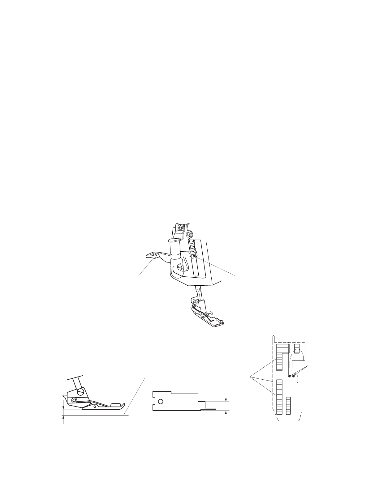
PRESSER BAR HEIGHT
Correct Setting:
The distance between the surface of needle plate and bottom of presser foot should be 4.7 to
5.3 mm when the presser bar lifter is raised.
To adjust:
1. Remove the looper cover unit, face plate unit, back cover unit and front cover unit.
2. Raise the presser bar lifter and loosen set screw A.
Then adjust the presser bar height (Use the service gauge O.L G05.). The presser foot
should be parallel with the slots of the needle plate.
3. Tighten the set screw A.
4. Attach the front cover unit, looper cover unit, back cover unit and face plate unit.
Top surface of needle plate
4.7 ~ 5.3 mm
5 mm
O. L G05
To be parallel
(Direction of presser foot)
Setscrew A
Presser bar lifter
Needle
MECHANICAL ADJUSTMENT
Table of contents


