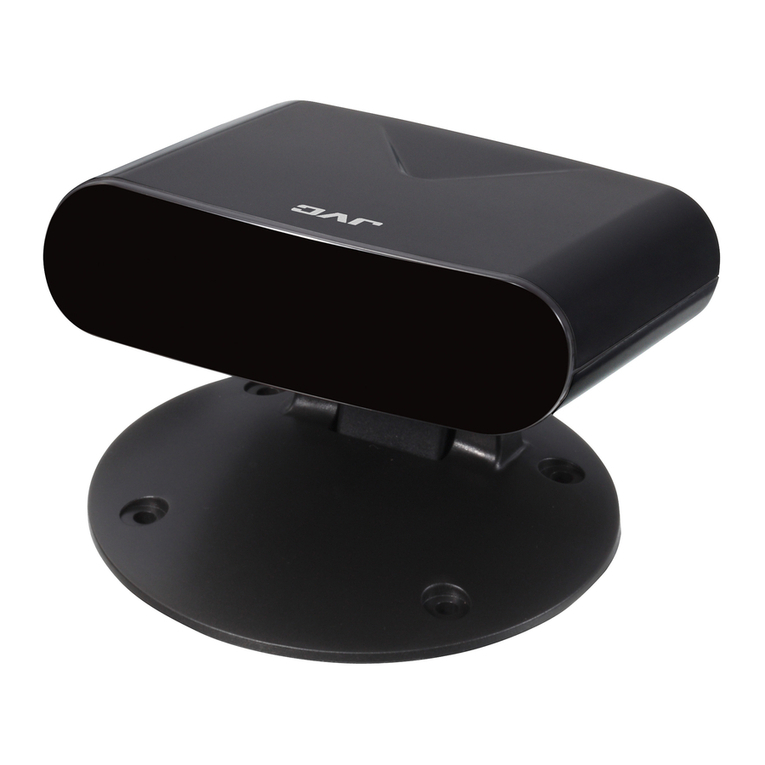
JVC PK-EXT40TG User manual

ネットワーク設定
Optical DVI Transmitter
INSTRUCTIONS/取扱説明書
PK-EXT40TG
PK-EXT40T
LCT2725-001A
Optical DVI Extender PK-EXT40T
Opt
1234
Sink
Source
Dual
お買い上げありがとうございます。
ご使用の前にこの「取扱説明書」をお読みのうえ、正しくお使
いください。また、「安全上のご注意」は必ずお読み頂き、安
全にお使いください。お読みになったあとは、大切に保管し、
必要なときお読みください。
設置工事は販売店へご依頼ください。
Thank you for purchasing this product.
Please read through this “INSTRUCTIONS” in advance to
ensure proper use of the product. Also, please make sure that
you read through the “Safety Precautions” to learn how to use
this product safely. After reading, keep this manual in a safe
place for future reference.
To request for installation, please contact our dealer. For Customer use :
Enter below the serial No. which is
located on the rear side of the
cabinet. Retain this information for
future reference.
Model No. PK-EXT40TG
Serial No.
PK-EXT40TG_EN.book Page 1 Tuesday, April 23, 2013 1:53 PM

2
Dear Customer,
This apparatus is in conformance with the valid
European directives and standards regarding
electromagnetic compatibility and electrical safety.
European representative of JVC KENWOOD
Corporation is:
JVC Technical Services Europe GmbH
Konrad-Adenauer-Allee 1-11
61118 Bad Vilbel
Germany
oStop using this product if any of the
abnormalities below is detected
Otherwise, it may cause fire or electric shock.
●When smoke, unusual odor, or other abnormal
symptoms are found.
●When the unit is not functioning properly, such as
when there is no image on the display or no sound.
●When water or other foreign object gets into the unit.
●When the cabinet is damaged from dropping.
●When the power cable is damaged. (Exposure or
breaking of the cable core, etc.)
If any of the above occurs, turn off the power
immediately, and unplug the power cable from the
outlet.
If smoke is detected, confirm that smoke has stopped
emitting before sending the product to the dealer for
repair.
You must not attempt to repair the product on your own.
Doing so may be dangerous.
oDo not block the ventilation holes
Blocking the ventilation holes may cause heat to trap
inside the unit and result in fire.
oDo not dismantle or modify the product
The product may malfunction or break down.
oDo not damage the power cable
Damaging the power cable may cause fire or electric
shock.
●Do not alter the power cable.
●Do not bend, twist, or pull the cable by force.
●Do not place equipment or other heavy objects on
the power cable.
●Do not place the power cable near a heating
equipment.
oDo not place the product on an unstable surface.
Do not place the product on an unstable platform or
inclined surface. The unit may fall off, causing it to
malfunction or break down.
oDo not place heavy objects on the product
If heavy objects or those with a bigger size than the unit
are placed on it, the product may lose its balance and
fall off, thus causing injuries.
oUnplug the power cable if the product is not to
be used for a long time
For reasons of safety and energy conservation, unplug
the power cable if you are not using it again soon.
oDo not pull the cord when unplugging the power
cable
Pulling the power cable at the cord may damage it,
causing fire or electric shock. To unplug, pull out by
holding the plug.
oDo not unplug power cable with wet hands
Doing so may cause electric shock.
oUnplug the power cable and disconnect all
cables before moving the unit
Moving the unit with the cables connected may
damage the cables, causing fire or electric shock.
Locations of Storage and Use
oDo not place this product at the following
locations.
Doing so may cause the product to malfunction or
break down.
●Hot or cold places beyond the allowable operating
temperature range (10 °C to 35 °C)
●Places that emit a strong magnetic field, such as
near transformers and motors
●Places near devices that emit radio waves, such as
transceivers and mobile phones
●Places with considerable dust and sand
●Places subject to strong vibrations
●Places where water droplets may be formed, such as
window sides
●Places that emit radiation, X-rays, and corrosive
gases
Handling Precautions
oDo not stack the devices on one another during
use.
Heat and noise from the other units may cause the
product to malfunction or break down, and result in fire.
oDo not block the ventilation holes
Doing so may cause heat to trap inside the unit and
result in fire. Do not use this product by laying it down
sideways, upside down, or at an angle.
oDo not insert objects into this unit.
Metallic or other flammable objects that get into this
unit, such as through the ventilation holes, may result
in fire or electric shock.
Maintenance
oTo clean this product, wipe it with a soft rag.
Wiping using thinner or benzene may cause the surface
to melt or fog. When the surface is extremely dirty, wipe
using a cloth that is dipped into a neutral detergent
diluted with water, followed by wiping with a dry cloth.
Energy Conservation
oFor reasons of safety and energy conservation,
unplug the power cable if you are not using the
product again soon.
Safety Precautions Precautions for Proper Use
PK-EXT40TG_EN.book Page 2 Tuesday, April 23, 2013 1:53 PM

3
PK-EXT40TG (Transmitter Unit)
A[Opt] Indicator
Lights up when an optical fiber cable is connected
between the optical transmitter and optical receiver units,
and appears blinking if cable is not connected.
B[Sink] Indicator
Lights up when a monitor display is connected. (Monitors
HPD)
C[Source] Indicator
Lights up when a video signal generator is connected.
(Monitors +5 V supply)
D[Dual] Indicator
Lights up when there is a dual-link signal input.
E[OPT] Optical Output Terminal
For connecting a 12-fiber MPO connector cable.
F[DVI-D] Input Terminals 1 to 4
These are video signal input terminals. Use them for
transmitting Type 1 to 4 dual-link DVI-D signals. (The
Status LED and channel number on the front panel are
linked.)
GPower Input Terminal
For connecting the supplied power cable.
Connect the cable to an AC 100 V - 240 V power supply.
oThis equipment is in conformity with the
provisions and protection requirements of the
corresponding European Directives.
This equipment is designed for professional
appliances in large scale fixed installations and
can be used in the following environments.
●Controlled EMC environment (for example purpose
built broadcasting or recording studio), and the rural
outdoors environment (far away from railways,
transmitters, overhead power lines, etc).
In order to keep the best performance and furthermore
for electromagnetic compatibility we recommend to use
the cables not exceeding the following length:
Cables Length
AC power cord Power supply cord 1.8 m
DVI cable Shielded cable 3.0 m
Optical cable Shielded cable 50 m
●The inrush current of this apparatus is 9.5 amperes.
Part Names and Functions
Front Panel
Optical DVI Extender PK-EXT40T
Opt
1234
Sink
Source
Dual
ABCD
Rear Panel
OPT
DVI-D
(Dual link)
100
l
240
VAC
1
3
2
4
EFG
EMC Supplement (Europe only)
WARNING
This is a Class A product. In a domestic environment
this product may cause radio interference in which case
the user may be required to take adequate measures.
In case where the strong electromagnetic waves or
magnetism are near the signal cable, the picture will
contain noise. In such cases, please keep the cable
away from the sources of the disturbance.
PK-EXT40TG_EN.book Page 3 Tuesday, April 23, 2013 1:53 PM

4
1Connect the video signal source to the
optical transmitter unit (PK-EXT40TG) using
the Dual-Link DVI cable
2Connect the projector to the Graphics
Interface (PK-VS4GD3G) using the Dual-Link
DVI cable
3Connect the optical transmitter unit
(PK-EXT40TG) to the Graphics Interface (PK-
VS4GD3G) using the optical fiber cable
●Align the orientation of the keyway for the optical
fiber cable’s plug with that for the connectors of the
optical transmitter and optical receiver units, and
insert it all the way in until a “click” sound is heard.
4Connect the supplied power cables to the
optical transmitter unit (PK-EXT40TG) and
Graphics Interface (PK-VS4GD3G), and
connect the other end of the cables to a
power supply.
Precautions when Connecting Optical Fibre Cable:
●Do not use cables that do not meet the allowable
bending radius. Refer to the instruction manual for the
“Optical Fiber Cable”.
●Lay the optical cable ensuring that no heavy objects
are placed on it, no one steps on it, and it is not caught
in the door.
●If a part of the optical cable is subject to stress, protect
the section such as by using a cover.
●After plugging the optical cable into the unit, make
sure that the base of the cable plug is not bent acutely.
1Perform installation according to [Installation
and Connection]
2Turn on the power for the optical transmitter
and optical receiver units
●After connection is established, the AOptBStatus
LED on the optical transmitter and optical receiver
units will light up.
Caution:
If AOptBdoes not light up, check for the following.
●Improper connection of the connectors
: Check the connection.
●Dirt on the connector terminal surface
: Clean the terminal surface.
●Broken optical fiber cable
: Check connection using a different cable.
3Turn on the power of the video signal source
●The ASourceBStatus LED on the optical transmitter
and optical receiver units light up.
4Turn on the power of the projector
●The ASinkBStatus LED on the optical transmitter
and optical receiver units light up.
●Image appears on the monitor display.
Notes:
●To enhance the service life of the product, prevent the
device temperature from rising too high such as by
adjusting the surrounding temperature or using a fan.
Installation and Connection
100
l
240
VAC
CONTROL
DC IN 12V
DVI 4 OUT
REMOTE EXT. CONTROL
DVI 3OUTDVI 2 OUTDVI 1 OUT
SYNC
IN
USB OPT
LAN
Dual-Link
DVI Cable (Sold Separately)
2 m or
shorter
Optical Fiber Cable
EF-FC1150G (Sold Separately) Dual-Link
DVI Cable (Sold Separately)
Projector
PK-VS4GD3G
Graphic Interface
(Sold Separately)
AC 100 V to 240 V
PK-EXT40TG
Tx Unit
Video Signal Source
AC 100 V to 240 V AC Adapter
Operation
PK-EXT40TG_EN.book Page 4 Tuesday, April 23, 2013 1:53 PM

5
PK-EXT40TG_EN.book Page 5 Tuesday, April 23, 2013 1:53 PM

6
PK-EXT40TG
Power Supply : AC 100 V to 240 V
Power Consumption : 20 W
Allowable Operating Temperature : 10 °C to 35 °C
Dimensions : 213 mm x 42 mm x 330 mm (W x H x D)
Mass : 2.06 kg (3.4 kg: with packaging and attachments included)
Terminal : DVI-D x 4, MPO x 1
Transfer rate : Up to 40 Gbps
Maximum resolution supported : 4096 x 2400
Attachments/Accessories : INSTRUCTIONS ..…...…1
Warranty Card ….........…1
Power cable (1.5 m) …….2 pcs
* The specifications and appearance of this unit may be modified for improvement without prior notice.
* PK-EXT40TG is intended for use in “large scale fixed installations”.
Specifications
PK-EXT40TG_EN.book Page 6 Tuesday, April 23, 2013 1:53 PM

ネットワーク設定
Optical DVI Transmitter
PK-EXT40T 取扱説明書
PK-EXT40T.book Page 1 Tuesday, April 23, 2013 1:43 PM

2
この取扱説明書と製品には、いろいろな絵表示が記載されています。これらは、製品を安全に正しくお使いいただ
き、お客様や他の人々への危害や財産の損害を未然に防止するための表示です。絵表示の意味をよく理解してから
本文をお読みください。
絵表示の説明
o万一、次のような異常が発生したときは、そのま
ま使用しない
火災や感電の原因となります。
●煙が出ている、へんなにおいがするな
どの異常のとき。
●画面が映らない、音が出ないなどの故
障のとき。
●内部に水や物が入ってしまったとき。
●落としたり、キャビネットが破損した
とき。
●電源コードが傷んだとき。(芯線の露
出、断線など)
このようなときは、すぐに電源を切り、電源
プラグをコンセントから抜いてください。
煙が出ているときは、止まったのを確かめて
から販売店に修理を依頼してください。
お客様ご自身が修理することは危険です。絶
対にやめてください。
o通風孔をふさがない
通風孔をふさぐと、内部に熱がこもり火災の
原因となります。
o分解・改造しない
破損や故障の原因となります。
o電源コードを傷つけない
電源コードを傷つけると、火災や感電の原因
となります。
●電源コードを加工しない。
●無理に曲げたり、ねじったり、引っ張っ
たりしない。
●電源コードの上に機器本体や重いもの
をのせない。
●電源コードを熱器具に近づけない。
安全上のご注意
絵表示について
この表示(文字含む)を無視して、誤った取り扱いをすると、人が死亡または重傷を負う可能
性が想定される内容を示しています
この表示(文字含む)を無視して、誤った取り扱いをすると、人が傷害を負ったり、物的損害
の発生が想定される内容を示しています
䢇注意(警告を含む)が必要な
ことを示す記号
䢇してはいけない行為(禁止行為)を
示す記号
䢇必ずしてほしい行為(強制・
指示行為)を示す記号
一般的注意 禁止 ぬれ手禁止 分解禁止 電源プラグを抜く
一般的注意
電源プラグ
を抜く
禁止
分解禁止
禁止
PK-EXT40T.book Page 2 Tuesday, April 23, 2013 1:43 PM

3
この装置は、クラス A 情報技術装置です。この装置を家庭環境で使用すると電波妨害を引き起こすことがあり
ます。この場合には使用者が適切な対策を講ずるよう要求されることがあります。
o不安定な場所に置かない
ぐらついている台の上や傾いた所に置かない
でください。落ちたりして機器の破損や故障
の原因となります。
oこの機器の上に重いものを置かない
重いものや本体からはみ出るような大きな物
を置くと、バランスがくずれて倒れたり落ち
たりして、けがの原因となることがあります。
o長期間使用しないときは、電源プラグ
を抜く
安全および節電のため、電源プラグを抜いて
ください。
o電源プラグはコードの部分を持って抜かない
電源コードを引っ張ると、コードに傷がつき、
火災・感電の原因となることがあります。プ
ラグの部分を持って抜いてください。
oぬれた手で電源プラグを抜き差ししない
感電の原因となることがあります。
o移動するときは、電源プラグや接続
コードを外す
接続したまま移動すると、コードに傷がつき、
火災や感電の原因となることがあります。
保管および使用場所
o次のような場所に置かない
誤動作や故障原因になります。
●許容動作温度(10 ℃〜 35 ℃)範囲外の暑いとこ
ろや寒いところ
●変圧器やモーターなど強い磁気を発生するところ
●トランシーバーや携帯電話など電波を発生する機
器の近く
●ほこりや砂の多いところ
●振動の激しいところ
●窓ぎわなど水滴の発生しやすいところ
●放射線やX線、および腐食性ガスの発生するとこ
ろ
取り扱いについて
o機器を重ねて使用しない
お互いの熱やノイズの影響で誤動作したり故障し
たり、火災の原因となることがあります。
o通風孔をふさがない
通風孔をふさぐと、内部の熱が逃げないので火災の
原因となります。本機を横倒し、逆さま、あお向け
の状態でご使用しないでください。
o内部に物を入れない
通風孔などから、金属類や燃えやすいものなどが入
れると火災や感電の原因となります。
お手入れについて
o本機はやわらかい布でふいてください。
シンナーやベンジンでふくと表面が溶けたり、く
もったりします。汚れがひどいときは、水でうすめ
た中性洗剤を布につけてふき、あとでからぶきして
ください。
省エネについて
o長時間使用しないときは、安全および節電のた
め、電源プラグを抜いてください
禁止
禁止
電源プラグ
を抜く
禁止
ぬれ手禁止
電源プラグ
を抜く
使用上のご注意
PK-EXT40T.book Page 3 Tuesday, April 23, 2013 1:43 PM

4
PK-EXT40T ( 送信ユニット )
A[Opt] インジケーター
光送信ユニット、光受信ユニット間にて光ファイバーが
接続されているときに点灯、接続されていないときに点
滅します。
B[Sink] インジケーター
映像表示器が接続されているときに点灯します。(HPD
をモニター )
C[Source] インジケーター
映像信号発生器が接続されているときに点灯します。
(+5V供給をモニター )
D[Dual] インジケーター
DualLinkの信号がある場合に点灯します。
E[OPT] 光出力端子
12 心の MPO コネクターケーブルを接続します。
F[DVI-D] 入力端子1 〜 4
映像信号の入力端子です。1 〜 4系統の Dual-Link
DVI-D信号を接続します。(フロントパネルの Status
LEDとチャンネル番号はリンクします。)
G電源入力端子
付属の電源コードを接続します。
AC100V に対応した電源を接続します。
各部の名称とはたらき
前面
Optical DVI Extender PK-EXT40T
Opt
1234
Sink
Source
Dual
ABCD
背面
OPT
DVI-D
(Dual link)
100
l
240
VAC
1
3
2
4
EFG
PK-EXT40T.book Page 4 Tuesday, April 23, 2013 1:43 PM

5
1映像信号源と光送信ユニット (PK-EXT40T)
を、Dual-LinkDVI ケーブルで接続する
2
プロジェクターと GraphicsInterface(PK-
VS4GD3) を、Dual-LinkDVI ケーブルで接続
する
3光送信ユニット (PK-EXT40T) と Graphics
Interface(PK-VS4GD3) を、光ファイバー
ケーブルで接続する
●光ファイバーケーブルのプラグのキー溝と、光送
信ユニットと光受信ユニットのコネクターのキー
溝の向きを合わせてカチッと音がするまで挿
入します。
4光送信ユニット (PK-EXT40T) と Graphics
Interface(PK-VS4GD3) に、付属の電源
コードを接続し AC 電源に接続する
光
ファイバーケーブル配線上のご注意:
●許容曲げ半径以下では使用しないでください。光
ファイバーケーブルの取扱説明書をご覧ください。
●光ケーブルの上に荷物や人が乗らない場所、ドアな
どではさまない場所に配置してください。
●光ケーブルに部分的に圧力のかかるところには、光
ケーブルをカバーなどで保護してください。
●ユニットへ光ケーブルのプラグを差し込んだ後に、
光ケーブルがプラグの根元で鋭く曲がらないように
注意してください。
1「設置・接続」に従って設置する
2光送信ユニットおよび光受信ユニットの電源を
入れる
●接続が確認されると光送信ユニットおよび光受信
ユニットの StatusLED の AOptBが点灯します。
ご注意:
AOptBが点灯しない場合は、下記の項目をご確認願いま
す。
●コネクター部の接続が不十分
:接続を確認してください。
●コネクター端子面へのゴミ付着
:端子面の清掃をしてください。
●光ファイバーケーブルの断線
:別のケーブルで確認してください。
3映像信号源の電源を入れる
●光送信ユニットおよび光受信ユニットの Status
LED の ASourceBが点灯します。
4プロジェクターの電源を入れる
●光送信ユニットおよび光受信ユニットの Status
LED の ASinkBが点灯します。
●モニターに表示されます。
メモ:
●環境温度、送風などにより機器の温度が著しく上昇
しないようにすることにより、本体機器の寿命を延
ばす効果があります。
設置・接続
100
l
240
VAC
CONTROL
DC IN 12V
DVI 4 O UT
REMOTE EXT. CONTROL
DVI 3 OUTDVI 2 OUTDVI 1 OUT
SYNC
IN
USB OPT
LAN
Dual-Link
DVI ケーブル(別売)
2m 以下
光ファイバーケーブル
EF-FC1150(別売) Dual-Link
DVI ケーブル(別売)
プロジェクター
PK-VS4GD3
GraphicInterface
(別売) AC100V
PK-EXT40T
Tx ユニット
映像信号源
AC アダプター
操作
AC100V
PK-EXT40T.book Page 5 Tuesday, April 23, 2013 1:43 PM

〒221-0022 神奈川県横浜市神奈川区守屋町三丁目12番地
ホームページhttp://www3.jvckenwood.com/
© 2013JVCKENWOOD Corporation LCT2725-001A
PK-EXT40TG
PK-EXT40T
Optical DVI Transmitter
PK-EXT40T
電源 :AC100V
消費電力 :20W
許容動作温度範囲 :10℃〜35℃
外形寸法 :213mmx42mmx330mm
(幅x高さx奥行き)
質量 :2.06kg (3.4kg:梱包・添付物含む)
端子 :DVI-Dx4、MPOx1
転送レート :最大 40Gbps
最大対応解像度 :4096x2400
添付物・付属品
:取扱説明書…………………1
保証書………………………1
電源コード(1.5m)……1 本
T本機の仕様および外観は、改善のため予告なく変更することがあります。
T本機は「JISC61000-3-2適合品」です。
仕様
PK-EXT40T.book Page 6 Tuesday, April 23, 2013 1:43 PM
This manual suits for next models
1
Table of contents
Other JVC Transmitter manuals
Popular Transmitter manuals by other brands

Sennheiser
Sennheiser SK 500 G3 Specifications

Elinchrom
Elinchrom El-Skyport user manual

Vaisala
Vaisala INTERCAP HMDW80 SERIES user guide

Primex
Primex XR 5 Watt Install & operation guide

Sentera Controls
Sentera Controls DSMFM-2R Mounting and operating instructions

Infineon
Infineon WLC MP-A2 50-W quick start guide