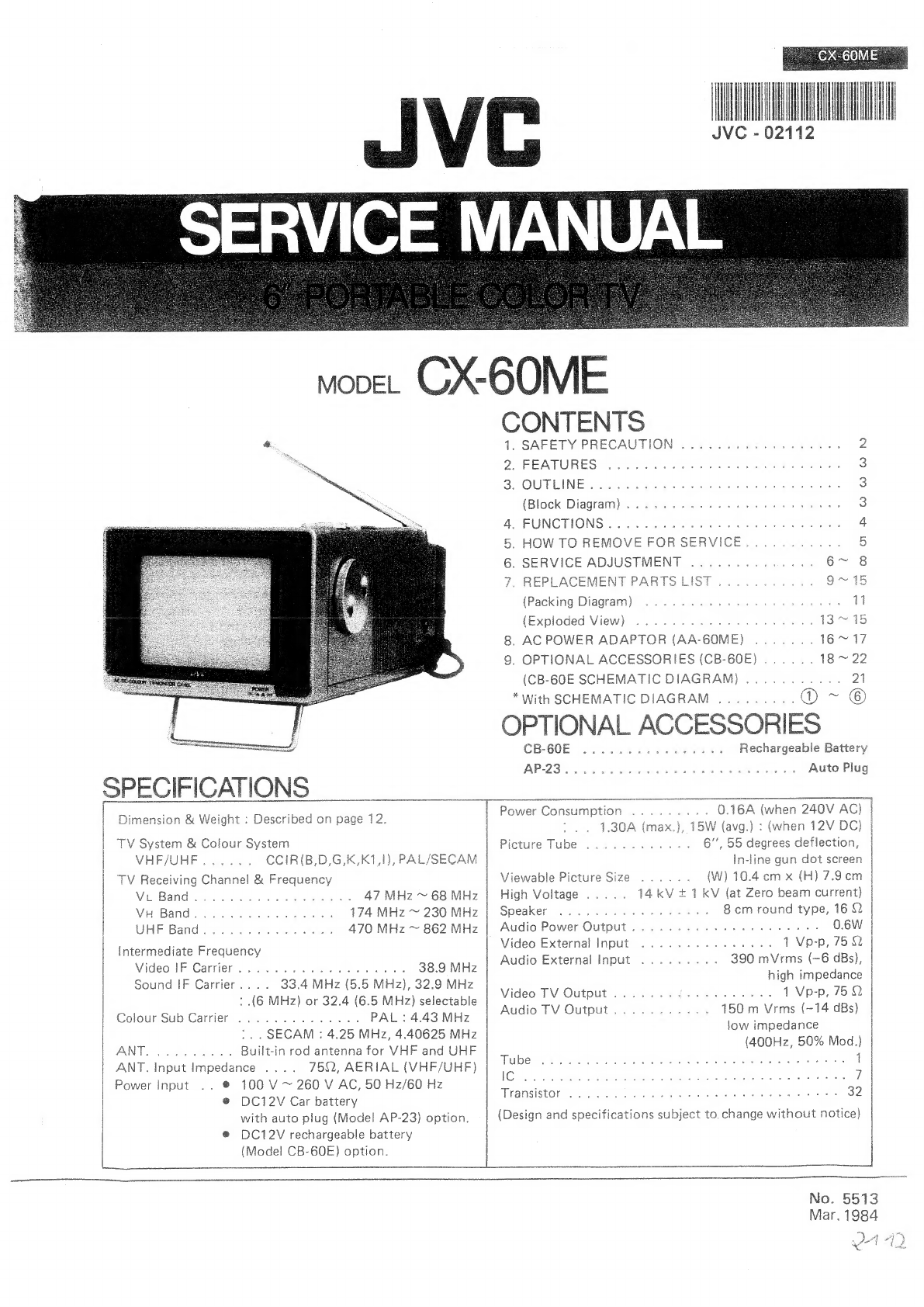
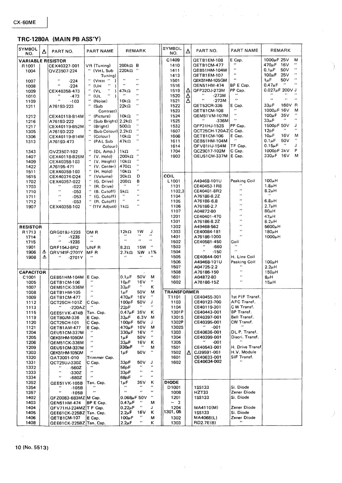
JVC CX-60ME User manual
Other JVC TV manuals

JVC
JVC AV-32Z25EUY User manual

JVC
JVC AV-29FH1BU Quick start guide
 User manual")
JVC
JVC AV-20N8(BK) User manual

JVC
JVC PD-42V31BJE User manual

JVC
JVC AV-21PS4N User manual

JVC
JVC LT-37DF7BC User manual

JVC
JVC 0305MKH-CR-MU User manual

JVC
JVC I Art AV-20F476 User manual

JVC
JVC AV-21F9 User manual

JVC
JVC AV-20NX3 User manual

JVC
JVC AV-21WH3 User manual

JVC
JVC AV-14FT15 User manual

JVC
JVC AV-21RT4SP User manual

JVC
JVC AV-28GT1BJF, AV-28GT1SJF User manual

JVC
JVC AV-20F703 User manual

JVC
JVC AV-29L6SU, AV-29L6BU User manual

JVC
JVC AV-32WFT1EPS User manual

JVC
JVC C-13310/S User manual

JVC
JVC AV-28T5BK/P User manual

JVC
JVC AV-27D303/S User manual