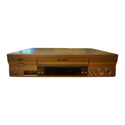
JVC HR-V200Ez User manual

COPYRIGHT © 2003 VICTOR COMPANY OF JAPAN, LTD
SERVICE MANUAL
g e n e r a l
Power: 200 V – 240 V, 50 Hz/60 Hz
Power consumption : Power on : Approx. 12 W : tandby mode:3.0 W
Video Head system : DA4 (Double Azimuth) head helical scan system
Tape speed
( P) : 23.39 mm/sec
(LP) : 11.69 mm/sec
Tape format : Tape width 1/2" (12.7 mm high density VH tape)
Maximum recording time
( P) : 240 min. with E-240 video cassette
(LP) : 480 min. with E-240 video cassette
Rewind time : Approx. 180 sec. with E-180 cassette
Dimensions (W x H x D) : 360 mm x 94.5 mm x 270 mm
Weight : 4.0 kg
Operating temperature : 5 °C to 35 °C
Operating humidity : Less than 80 %
Timer: 24 hours display type
vi eo
ignal system: PAL-type colour signal and CCIR monochrome signal, 625 lines 50 fields
Recording Format : PAL I
RF reception : PAL I
RF OUT : PAL I
RF modulator: UHF channels 22 – 68 (Adjustable)
Input level : VIDEO IN ( CART type) 1.0 Vp-p, 75 ohm, unbalanced
Output level : VIDEO OUT ( CART type) 1.0 Vp-p, 75 ohm, unbalanced
ignal-to-noise ratio : More than 43 dBm
au io
Input level : AUDIO IN ( CART type) –6.0 dBm, more than 10 kΩ
Output level : AUDIO OUT ( CART, RCA type) –6.0 dBm, less than 1 kΩ
Audio track : Mono track and Hi-Fi track
Audio frequency response
Normal audio : 100 Hz to 10,000 Hz (–6/+3 dBm)
Hi-Fi audio : 20 Hz to 20,000 Hz (–3/+3 dBm)
Audio signal to noise ratio
Hi-Fi audio : More than 70 dB (JI A filter)
Audio dynamic range
Hi-Fi audio : More than 85 dB (JI A filter)
accessories
Provided accessories : RF cable, Infrared remote control unit, “CR 2032” battery x 1
pecifications shown are for P mode unless otherwise specified.
E.& O.E. Design and specifications subject to change without notice.
No.82963
2003/05
HR-V200EZ, HR-V205EK,
HR-V500EZ, HR-V505EK, HR-V505EZ
HR-V200EZ, HR-V205EK, HR-V500EZ, HR-V505EK, HR-V505EZ, V16A0,A1,D0,D1-
VIDEO CASSETTE RECORDER
S PECIFICATIONS
(The specifications shown pertain specifically to the model HR-V505EK.)
PAL

1-5
In case that defective EEPROM of PAL models is replaced, to operate these sets from the initial state MP KEY
must be repaired as well before delivering to the customer.
If MP KEY isn’t repaired the setting of RF OUT channel or LANGUAGE might be different from that for cus-
tormer’s country.
•MP KEY : In case of PAL VCR if holding the REC button on the front panel and the CLEAR button on the
remote control handset for 5 ~ 7 seconds with power being switch all and no tapes,
OK is displayed at FLD for FLD models and LED becomes on for LED CLOCK models.
This is the state that initializing EEPROM is finished.
(In case of PAL VCP if holding the REC button on the front panel and the MENU button on the
remote control handset for 5 ~ 7 seconds with power being off and no tapes, All the LED DOTs
become on. This is the state that initializing EEPROM is finished.)
•MP KEY's function : MP KEY sets EEPROM's data up to the initial state.
SERVICE NOTICE ON REPLACING EEPROM
TIMER
AM
REC
VCR
OK
• FLD MODEL:
MP KEY “OK”
• LED CLOCK MODEL:
MP KEY Switch all on a Light
• LED DOT MODEL:
MP KEY Switch all on a Light

1-6
SERVICE INFORMATION FOR EEPROM IC SETTING
MODEL NAME HEX BINARY
HR-V200EX OPTION1 02 00000000
OPTION2 C0 00000000
OPTION3 87 00000000
OPTION4 B1 00000000
OPTION5 30 00000000
OPTION6 08 00000000
HR-V200EY OPTION1 02 00000000
OPTION2 C0 00000000
OPTION3 87 00000000
OPTION4 B1 00000000
OPTION5 B0 00000000
OPTION6 08 00000000
HR-V200EL OPTION1 02 00000000
OPTION2 C0 00000000
OPTION3 87 00000000
OPTION4 B1 00000000
OPTION5 A0 00000000
OPTION6 08 00000000
HR-V205EX OPTION1 E2 00000000
OPTION2 C1 00000000
OPTION3 8F 00000000
OPTION4 B1 00000000
OPTION5 30 00000000
OPTION6 68 00000000
HR-V205EY OPTION1 E2 00000000
OPTION2 C1 00000000
OPTION3 8F 00000000
OPTION4 B1 00000000
OPTION5 B0 00000000
OPTION6 68 00000000
HR-V205EL OPTION1 E2 00000000
OPTION2 C1 00000000
OPTION3 8F 00000000
OPTION4 B1 00000000
OPTION5 A0 00000000
OPTION6 68 00000000
HR-V206EX OPTION1 E2 00000000
OPTION2 C1 00000000
OPTION3 8F 00000000
OPTION4 B1 00000000
OPTION5 30 00000000
OPTION6 68 00000000
MODEL NAME HEX BINARY
HR-V206EY OPTION1 E2 00000000
OPTION2 C1 00000000
OPTION3 8F 00000000
OPTION4 B1 00000000
OPTION5 B0 00000000
OPTION6 68 00000000
HR-V206EL OPTION1 E2 00000000
OPTION2 C1 00000000
OPTION3 8F 00000000
OPTION4 B1 00000000
OPTION5 A0 00000000
OPTION6 68 00000000
HR-V500EX OPTION1 0C 00000000
OPTION2 C0 00000000
OPTION3 83 00000000
OPTION4 B1 00000000
OPTION5 30 00000000
OPTION6 08 00000000
HR-V500EY OPTION1 0C 00000000
OPTION2 C0 00000000
OPTION3 83 00000000
OPTION4 B1 00000000
OPTION5 B0 00000000
OPTION6 08 00000000
1. DETECT NEW EEPROM (OPTION EDIT SCREEN)
- Eeprom EDIT screen automatically appears if replacing Eeprom.
• Setup option data using the cursor Up/Down key of a remote
control.
(Setup upon BOM depending on OPT1~OPT6 model)
• Since an initial remote control is set to LG for LG model, appro-
priately set optional data using the cursor Up/Down key.
2. EEPROM WRITED COMPLETE SCREEN
- Writes data on EEPROM by using REMOCON "OK".
- If completing the option data screen with a menu key, Powering
Off is automatically done and the option edit screen is arranged.
3. PG ADJUST
a) Insert the PAL SP Test Tape and play.
Note - Adjust the distance of X, pressing the Tracking(+) or
Tracking(-) when the “ATR” is blink after the PAL SP Test
Tape is inserted.
b) Press the Auto PG KEY on JIG Remocon(1’st) or Press “REC”
key on set and “CLEAR” key on Remocon.(Then check the blink
“TRK OK” on CLK/LED-TRK is a Initial)
c) Press the Auto PG Key on JIG Remocon again (2’nd) or press
“REC” key on set and “CLEAR” key on Remocon again.(Then
check the blink “PG NG > PG OK” on CLK/LED.)
4. EEPROM INITIAL
- SETUP is displayed in the field if pressing the FRONT REC KEY
with the remocon number "CLEAR" key pressed in the status of
powering Off.
- AUTO SEARCH is done since the initial screen of ACMS is ser-
viced if powering On.
- Check basic operation (PLAY/RECORD...)
EEPROM option code No. setting EEPROM option code No. setting procedure
NAME HEX BINARY
OPT1 00 00000000
OPT2 00 00000000
OPT3 00 00000000
OPT4 00 00000000
OPT5 00 00000000
OPT6 00 00000000
WR : OK I : EXIT MOVE : 8t
EDIT : 67E
MASKROM : R00
EEPROM : R00 LG CODE

1-7
MODEL NAME HEX BINARY
HR-V500EL OPTION1 0C 00000000
OPTION2 C0 00000000
OPTION3 83 00000000
OPTION4 B1 00000000
OPTION5 A0 00000000
OPTION6 08 00000000
HR-V505EX OPTION1 EC 00000000
OPTION2 C1 00000000
OPTION3 8B 00000000
OPTION4 B1 00000000
OPTION5 30 00000000
OPTION6 08 00000000
HR-V505EY OPTION1 EC 00000000
OPTION2 C1 00000000
OPTION3 8B 00000000
OPTION4 B1 00000000
OPTION5 B0 00000000
OPTION6 08 00000000
HR-V505EL OPTION1 EC 00000000
OPTION2 C1 00000000
OPTION3 8B 00000000
OPTION4 B1 00000000
OPTION5 A0 00000000
OPTION6 08 00000000
HR-V506EX OPTION1 EC 00000000
OPTION2 C1 00000000
OPTION3 8B 00000000
OPTION4 B1 00000000
OPTION5 30 00000000
OPTION6 08 00000000
HR-V506EY OPTION1 EC 00000000
OPTION2 C1 00000000
OPTION3 8B 00000000
OPTION4 B1 00000000
OPTION5 B0 00000000
OPTION6 08 00000000
HR-V506EL OPTION1 EC 00000000
OPTION2 C1 00000000
OPTION3 8B 00000000
OPTION4 B1 00000000
OPTION5 A0 00000000
OPTION6 08 00000000
HR-V507EX OPTION1 EC 00000000
OPTION2 C1 00000000
OPTION3 8B 00000000
OPTION4 B1 00000000
OPTION5 30 00000000
OPTION6 08 00000000
HR-V507EY OPTION1 EC 00000000
OPTION2 C1 00000000
OPTION3 8B 00000000
OPTION4 B1 00000000
OPTION5 B0 00000000
OPTION6 08 00000000
MODEL NAME HEX BINARY
HR-V507EL OPTION1 EC 00000000
OPTION2 C1 00000000
OPTION3 8B 00000000
OPTION4 B1 00000000
OPTION5 A0 00000000
OPTION6 08 00000000
HR-V200EZ OPTION1 02 00000000
OPTION2 C8 00000000
OPTION3 87 00000000
OPTION4 B7 00000000
OPTION5 00 00000000
OPTION6 30 00000000
HR-V500EZ OPTION1 0C 00000000
OPTION2 C8 00000000
OPTION3 83 00000000
OPTION4 B7 00000000
OPTION5 00 00000000
OPTION6 10 00000000
HR-V505EZ OPTION1 0C 00000000
OPTION2 C8 00000000
OPTION3 8B 00000000
OPTION4 B7 00000000
OPTION5 00 00000000
OPTION6 10 00000000
HR-V205EK OPTION1 02 00000000
OPTION2 C0 00000000
OPTION3 8B 00000000
OPTION4 A4 00000000
OPTION5 00 00000000
OPTION6 03 00000000
HR-V505EK OPTION1 2C 00000000
OPTION2 C0 00000000
OPTION3 8B 00000000
OPTION4 A4 00000000
OPTION5 00 00000000
OPTION6 03 00000000
HR-V205EF OPTION1 62 00000000
OPTION2 C0 00000000
OPTION3 0F 00000000
OPTION4 B0 00000000
OPTION5 62 00000000
OPTION6 00 00000000
HR-V505EF OPTION1 6C 00000000
OPTION2 C0 00000000
OPTION3 0B 00000000
OPTION4 B0 00000000
OPTION5 62 00000000
OPTION6 00 00000000
WR : OK I : EXIT MOVE :
EDIT : 67E
EEPROM option code No. setting EEPROM option code No. setting
8t

3-1
NICAM
(COMPONENT SIDE)
SCART JACK
Hi-Fi
SYSTEM
AVCP
Micom
T
U
N
E
R
Speak-ez SW/IC
SECAM
VPS
EEPROM
CLK IC
W501 H.S/W
E2PROM
C
+
S
M
P
S
A/V
W502
DISPLAY(DOT,CLK)
: Measurement point
: Adjustment point
SECTION 3 ELECTRICAL
ELECTRICAL ADJUSTMENT POINTS ARRANGEMENT

3-2
ELECTRICAL ADJUSTMENT PROCEDURES
1. Servo Adjustment
1) PG Adjustment
• Test Equipment
• Adjustment And Specification
a) OSCILLOSCOPE
b) PAL TEST TAPE (VHS SP)
c) JIG REMOCON (AUTO PG SETTING)
MODE
PLAY
• Adjustment Procedure
a) Insert the PAL SP Test Tape and play.
Note - Adjust the distance of X, pressing theTracking(+) or Tracking(-) when the “ATR” is blink after the
PAL SP Test Tape is inserted.
b) Press the Auto PG KEY on JIG Remocon(1’st) or Press “REC” key on set and “CLEAR” key on
Remocon.(Then check the blink “TRK OK” on CLK/LED-TRK is a Initial)
c) Press the Auto PG Key on JIG Remocon again (2’nd) or press “REC” key on set and “CLEAR” key on
Remocon again.(Then check the blink “PG NG > PG OK” on CLK/LED.)
• Check the PG
a) Connect the CH1 of the oscilloscope to the H/SW and CH2 to the Video out for the VCR.
b) Trigger the mixed Video Signal of CH2 to the CH1 H/SW(W501, W502), and then check the distance
(time difference), which is from the selected A(B) Head point of the H/SW(W501, W502) signal to the
starting point of the vertical synchronized signal, to 6.5H ±0.5H (416µs, 1H=64.0µs).
• CONNECTION
V.Out
H/SW(W501, W502) 6.5 ±0.5H
MEASUREMENT POINT ADJUSTMENT POINT SPECIFICATION
V.Out
H/SW(W501,W502)
OSCILLOSCOPE
CH1 CH2
V.out
H/SW
(W501, W502)

3-3
ELECTRICAL ADJUSTMENT PROCEDURES
• WAVEFORM
• Attension and Reference
a) The PG checking must do when RF Level is Maximum and SERVO system is Locking (MTR MODE)
b) V.H/SW Level is 2Vpp.
H/SW
Composite
VIDEO
6.5H(416us)

3-4
ELECTRICAL TROUBLESHOOTING GUIDE
1. Power Circuit(SMPS)
(1) No 5.3VA.
No 5.3VA.
Is the F101 normal?
Is the BD101 normal?
Is the R101 normal?
Does the oscillation waveform appear at
the IC101 Pin 7?
Is there DC voltage at the IC101 Pin 4?
Is there about 2.5V at the IC103 Vref ?
Is the D106 normal?
Check the Main PCB 5.3VA Line short?
Replace the F101
(Use the same Fuse).
Replace the BD101.
Replace the R101.
Is Vcc(about 13~15V) permittable at the
IC101 Pin 3?
Check or Replace the D103.
Replace the IC102.
Replace the IC103.
Replace the D106.
NO
YES
YES
YES
YES
YES
YES
YES
YES
NO
NO
NO
NO
NO
NO
NO

3-5
Is the D109 normal? Replace the D109.
Check 12VA Line of the Main PCB short.
YES
YES
No 12VA.
Does 5.3VA work normally? Check whether 5.3VA is out of order.
YES
NO
NO
7. Power Circuit(SMPS)
(2) No 12VA.(Capstan)
(3) No 12VA (CANAL, Buffer)
Is Voltage(about 12V) put into the
Q155(C)?
Check or Replace the Q155.
YES
YES
No 12VA.
Is Vcc(about 13VA) put into the Q155(E)? Replace the Peripheral Circuitry of D160.
YES
NO

7. Power Circuit(SMPS)
(4) No 5VT(5V)
Is about 4.7V put into the
Q152(Q151) Base? Check the Q163(Q162)
whether it works normally.
Check or Replace the Q152(Q151).
YES
YES
No 5VT.(5V)
Is the Q163(Q162) Base “H”?
Is 5.3VA put into the Q152(Q151)
collector?
Check the µ-com Control.
YES
YES
NO
NO
3-6

3-7
2. Servo Circuit
Unstable Video in PB
Mode.
Does the on screen noise
level change periodically?
Do CTL pulses appear at
IC501 pin 8?
Does the CFG divide
waveform appear at IC501
pin 9?
Do the CTL pulses move
when TRK is operated?
Replace IC501.
Does the Video Envelope
waveform appear at IC501
Pin 24?
NO
YES
YES
YES
YES
YES
A.
Is the height of the CTL
Head adjusted correctly?
NO
Replace IC501.
NO
Check AVCP IC.
NO
Adjust the CTL Head.

Drum Motor stopped.
Does 12V appear at PMC01 Pin 8?
Does 2.8V appear at PMD01 Pin 12?
Check Connector and Drum Motor Ass’y.
Check the Components and foil Pattern
between IC501 Pin 26 and PMC01
Pin 12 for shorts.
Does the Drum PWM waveform
appear at IC501 Pin 107?
Check the Components and foil Pattern
Connected to IC501 Pin 107 PMC01
Pin 12 for shorts.
Do DFG Pulses appear at IC501 Pin 104?
B.
NO
NO
NO
NO
Check Power.
Does Drum PWM appear at IC501 Pin
107?
Do DFG Pulses appear at PMD01 Pin 3?
Check Drum Monitor Ass’y.
Check the Components and foil pattern
between PMC01 Pin 11 and IC501
Pin 104 for shorts.
Replace IC501.
YES
YES
YES
YES
YES
NO
NO
3-8

3-9
Capstan Motor Stopped.
Check Power.
Does PWM wave appear at IC501
Pin 108?
Does the CFG signal appear at PMC01
Pin 1?
Check Capstan Motor Ass’y.
Check Components and foil patterns
between PMC01 Pin 7 and IC501
Pin 9 for shorts.
Replace IC501.
Does 13VA appear at PMC01 Pin 2?
Does 2.8V appear at PMC01 Pin 9?
Check Connector and Capstan
Motor Ass’y.
Check the Components and foil Patterns
Connected between IC501 Pin 108 and
PMC01 Pin 9 for shorts.
Does the CFG signal appear at IC501
Pin 9?
Does Capstan PWM appear at IC501
Pin 108?
Check the components and foil pattern
connected between IC501 Pin 108 and
PMC01 Pin 9 for shorts
C.
NO
NO
NO
NO
NO
YES
YES
YES
YES
YES
YES
NO

YES
YES
YES
Does 5.3V appear at
RS501.
Check the Power.
Check the Drum Motor
Signal.
Do Take-up reel pulses
appear at the base of
Q514?
Replace the Take-Up Reel
Photocoupler in the
Deck(RS501).
Auto stop.
Does SW30 waveform
appear at IC501 Pin 105?
Do Take-up reel pulses
appear at IC501 Pin 49?
Change IC501.
A.
NO
NO
NO
NO
YES
3. System & Front Panel Circuit
3-10

3-11
YES
YES
Cassette tape loading is unstable.
Is REG 14VA applied to PMC01 Pin 8?
Is High signal applied to IC501 Pin 30
when inserting the CST?
Does Low signal occur form PMC01
Pin 10 when inserting the CST?
Check the Deck Mechanism.
NOTE : Auto stop may also be caused by lack of lubrication,due to dried grease or oil.
Is 5.4VA applied to R544?
Check the power.
Check IC501 Pins 68, 69, 70, 71.
Check the CST SW and
peripheral circuitry. Check the power.
B.
NO
NO
NO
YES
NO
YES
Non working finction buttons.
Is the voltage of IC501 Pin 36, 5V?
Does(LED Ass’y) display change
when a function button is pressed?
Replace IC501.
Replace the defective switch.
Check the power.
Check IC506 Pins 6~14, 17, Pins 20~23
pulse output.
Replace IC506.
C.
YES
YES NO
NO

4. Y/C CIRCUIT
(1) No Video in EE Mode,
No Video in EE Mode
Check the Video Input
Jack.
(Line In Jack)
Does the Video signal
appear at the IC301 Pin 48?
Is 5V applied to the IC301
Pins 18, 24, 42, 55, 72, 91?
Does the Video signal
appear at the IC301 Pin 65?
Does the Video signal
appear at the IC501 Pin 19?
Does the Video signal
appear at the Emitter termi-
nal of the Q307, Q308?
Check the 5.2VT, 5.4VA
Line. (Power Circuit)
Is I
2
C BUS signal applied to
the IC301 Pins 68, 69?
Check C316. (AGC)
Chck the path of the signal
between the IC301 Pin 5
and IC501 Pin 17.
Replace the IC301.
Does the 12VT, 5.4VA
appear at the Emitter termi-
nal of the Q307, Q308.
Replace the Q307, Q308. Check the 12VT, 5.4VA
Line. (Power Circuit)
Check the System Circuit.
(Refer to ‘SYSTEM I
2
C BUS
CHECK Trouble Shooting’)
YES
YES
YES
YES
YES
YES
YES
NO
NO
NO NO
NO
NO
NO
3-12

3-13
3. Y/C CIRCUIT
(2) When the Y(Luminance) signal doesn’t appear on the screen in PB Mode,
Is 5.2VT, 5.4VA applied to the
IC301 Pins 24, 42, 55, 72, 91?
Is the I
2
C Bus siganl applied
to the IC301 Pins 68, 69 ?
Does the normal RF signal
appear at the IC301 Pin 78?
Check the line of the 5.2V
Line. (Power Circuit)
Check the System Circuit.
(IC501 Pin 105)
Check the V.H.S/W level.
(Check R303, R304)
Replace the IC301.
Refer to ‘SYSTEM I
2
C BUS
CHECK Trouble Shooting’.
Is the V.H.S/W signal
applied to the IC301 Pin 70?
Is V.H.S/W “H” about 3.4V
at the IC301 Pin 70?
Clean the Drum.
Check the path of the
Y(Luminance) RF signal.
(Check C327)
Check the path of the
Y(Luminance) RF signal.
(Check the C312)
Does the Y(Luminance) RF
signal appear at the IC301
Pin 76?
Is the Y(Luminance) Video
waveform showed up at
theIC301 Pin 43?
Replace the IC301.
NO
YES
YES
YES
YES
YES
YES
YES
YES
YES
NO
NO
NO
NO
NO
NO
NO

3. Y/C CIRCUIT
(3) When the C(Color) signal doesn’t appear on the screen in PB Mode,
Is 5.2VT/5.4VA applied to the
IC301 Pins 24, 42, 55, 72, 91.
Is the Color Rotary signal
applied to the IC301
Pin 70?
Does the Color signal
appear at the IC301
Pin 25 ?
Check the line of the 5.2VT/
5.4VA Line. (Power Circuit)
Replace the X301.
Check the Color Pass.
Check the Color Rotary
Circuit. (IC501 pin 99 )
Check the Color Rotary
level. (Check the R303)
Does the X301(4.43MHZ)
oscillate?
Replace the IC301.
Does the Color signal
appear at the IC301 Pin 21?
Is Color Rotary “H”
about 3.4V?
Replace the IC301.
NO
YES
YES
YES
YES
NO
NO
NO NO
NO
YES
3-14

3-15
3. Y/C CIRCUIT
(4) When the Video signal doesn’t appear on the screen in REC Mode,
Is the EE signal normal?
Is 5.2VT/5.4VA applied to the
IC301 Pins 24,42,55,72,91?
Does the RF signal appear
at the IC301 Pin 78?
Check EE Mode.
Check the System of REC
‘H’. (the IC501 Pin 47
/ the D301)
Replace the IC301.
Check the line of the 5.2VT/
5.4VA Line.(Power Circuit)
Check PB Mode.
Is the REC ‘H’ signal
(about 4V) applied to the
IC301 Pin 80?
Check the circuit of the
IC301 Pins 85, 86.
Check REC Luminance
Pass & Color Pass.
Does PB Mdoe operate
normally?
Does the REC RF signal
appear at the IC301
Pins 88,89,94,95?
Check the Drum &
Drum Connector
YES
YES
YES
YES
YES
NO
NO
NO
NO
NO
NO
YES
YES
YES

5. Tuner/IF circuit
(1) No picture on the TV screen
No picture on the
TV screen
Does the Video signal at
the TU701 Pin24? Check 33VT line.
Check 5VT line.
Check the liC Clock
signal of µ-com Pin 59.
Is +30VT applied to
TU701 Pin 16?
Is +5VT applied to
TU701 Pin 13?
Does the Clock signal
appear at TU701 Pin 11?
Does the data signal
appear at TU701 Pin 12?
Replace Tuner
Check the signal flow
from TU701 Pin 24 to
IC301 Pin 67.
Does Sync appear at
IC501 Pin111?
Check the signal flow from
IC501 Pin19 to JK901
Pin19.
YES
YES
YES
YES
YES
YES
YES
NO
NO
NO
NO
NO
Check the liC Data signal
of µ-com Pin 60.
NO
3-16
This manual suits for next models
4
Table of contents
Other JVC VCR System manuals