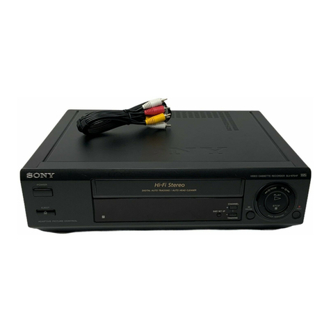
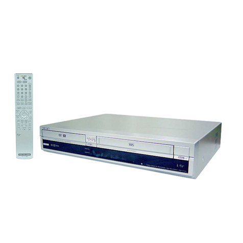
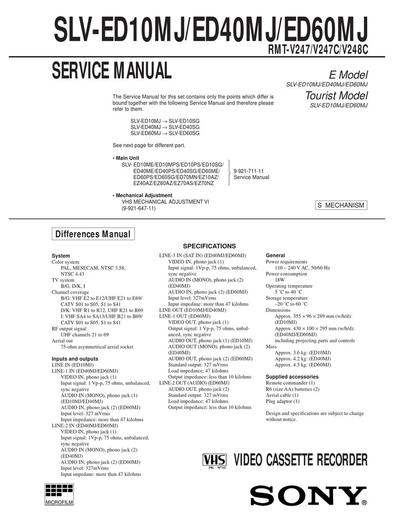
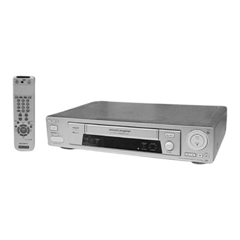
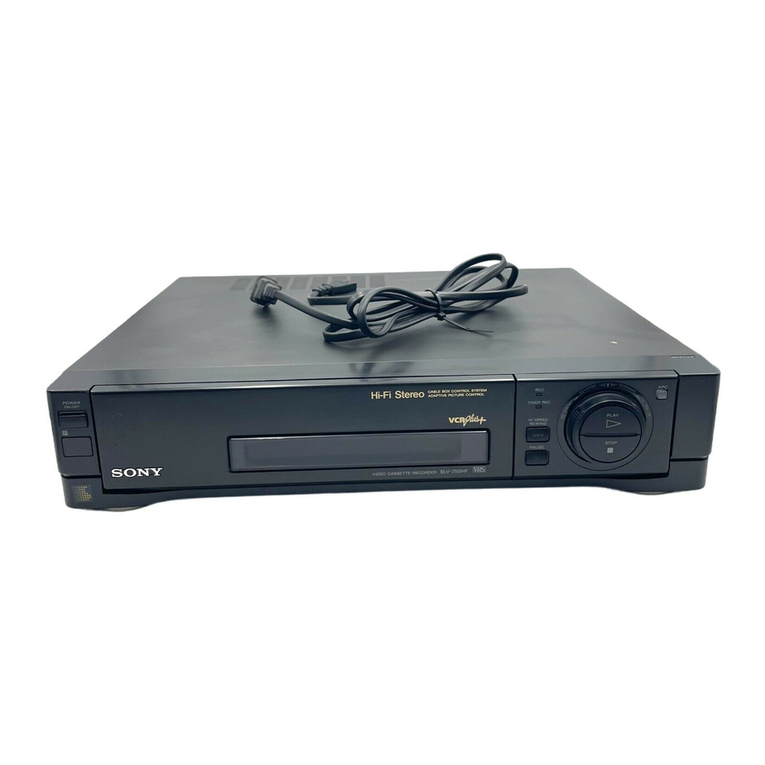
Sony SLV-798HF User manual

SLV-798HF/998HF
RMT-V229/V232C
US Model
SLV-798HF/998HF
Canadian Model
SLV-798HF/998HF
Chilean Model
Mexican Model
PX Model
SLV-998HF
SERVICE MANUAL
VIDEO CASSETTE RECORDER
MICROFILM
S MECHANISM
• Refer to the SERVICE MANUAL of VHS MECHANICAL
ADJUSTMENT for MECHANICAL ADJUSTMENTS.
(9-921-647-11)
G
jPhoto : SLV-998HF
SPECIFICATIONS

SLV-798HF/998HF
4-5
MA-318 (REC/PB AMP) SCHEMATIC DIAGRAM
— Ref. No.: MA-318 Board; 1,000 Series —
4-6 4-7
MA-318
REC/PB AMP, VIDEO, AUDIO,
SERVO/SYSTEM CONTROL,
TUNER
FR-130
(MODE CONTROL)
DM-74
(OPERATION SWITCHES)
POWER BLOC
K
JK-159
(LINE-2 IN)
MA-318
BOARD
1
IC260 4REC
2
IC260 #º REC
CN261 1REC
3
IC260 @• REC
20mV/Div
0.1µsec/div
0.5V/Div
0.1µsec/div
1V/Div
0.1µsec/div
4
IC260 @™ PB
200mV/Div
0.1µsec/div
5
IC260 !• REC/PB
2.3Vp-p
H
6
IC260 !¶ REC/PB
CN261 3REC/PB
5Vp-p
30Hz
MA-318 BOARD
CJ570 A-3
CN101 C-7
CN102 E-2
CN103 I-4
CN162 J-12
CN163 I-12
CN260 B-9
CN261 B-7
CN301 B-4
CN302 B-5
CN341 B-10
CN423 C-12
CN602 F-1
CN603 H-1
CN931 D-10
CNJ980 A-2
CNJ981 A-1
D103 F-6
D107 G-8
D109 F-4
D161 J-8
D370 C-10
D379 A-11
D502 C-1
D503 C-2
D504 C-2
D560 B-3
D561 A-10
D611 J-3
D612 J-3
D614 J-3
D702 F-12
D801 D-9
D802 D-9
D980 A-2
D981 A-2
D982 B-1
D983 A-1
D984 A-1
IC100 G-6
IC101 I-3
IC140 H-11
IC141 A-5
IC161 I-9
IC201 D-5
IC202 E-5
IC260 B-8
IC301 B-5
IC340 B-10
IC360 B-11
IC500 C-1
IC501 D-1
IC601 E-12
IC733 H-13
IC871 I-6
IC980 B-1
PH101 H-8
PH102 H-4
Q101 F-1
Q102 F-10
Q103 F-5
Q140 H-10
Q201 C-3
Q205 C-3
Q208 D-4
Q209 E-4
Q210 E-5
Q211 D-6
Q260 B-7
Q301 C-5
Q331 C-6
Q379 A-11
Q386 A-11
Q387 A-11
Q502 B-2
Q503 B-2
Q505 D-1
Q560 B-3
Q603 J-2
Q604 J-3
Q605 J-4
Q606 J-2
Q731 H-13
Q801 B-8
Q802 E-10
Q803 D-9
Q804 E-9
Q805 E-9
Q806 E-8
Q807 E-8
Q808 E-8
Q809 D-8
Q810 E-8
Q830 C-9
Q831 C-9
Q832 D-10
Q833 C-10
Q834 C-9
Q851 C-8
Q852 C-8
Q853 D-8
Q854 D-8
Q855 D-8
Q856 D-8
Q857 D-8
Q871 I-5
Q872 I-5
Q873 I-5
Q874 I-5
Q875 H-5
Q931 D-11
Q932 D-10
• For printed wiring boards.
•b: Pattern from the side which enables seeing.
Caution :
Pattern face side: Parts on the pattern face side
(Conductor Side) seen from the pattern face are
indicated.
Pattern face side: parts on the parts face side seen
(Component Side) from the parts face are indicated.
• For schematic diagrams.
• Caution when replacing chip parts.
New parts must be attached after removal of chip.
Be careful not to heat the minus side of tantalum
capacitor, because it is damaged by the heat.
• All resistor are in ohms, 1/4W unless otherwise noted.
Chip resistor are 1/10W unless otherwise noted.
kΩ:1000Ω, MΩ, : 1000kΩ.
• All capacitors are in µF unless otherwise noted. pF : µ
µF. 50V or less are not indicated except for electrolytics
and tantalums.
•C: panel designation.
• : internal component.
•A: B+ Line. *
•B: B– Line. *
•J : IN/OUT direction of (+,–) B LINE. *
• Circled numbers refer to waveforms. *
• Readings are taken with a color-bar signal input.
• Voltage are dc between ground and measurement
points.*
• Readingsare takenwith a digital multimeter (DC10MΩ).*
• Voltage variations maybenoted dueto normal production
tolerances.*
When indicating parts by reference number, please
include the board name.
• *: indicated by the color red.
THIS NOTE IS COMMON FOR PRINTEDWIRING
BOARDS AND SCHEMATIC DIAGRAMS.
(In addition to this, the necessary note is
printed in each block.)
REC/PB AMP
MA-318 (1/10)
SLV-798HF/998HF
MA-318 (VIDEO, NORMAL AUDIO) SCHEMATIC DIAGRAM
— Ref. No.: MA-318 Board; 1,000 Series —
• See page 4-3 for MA-318 BOARD printed wiring board.
MA-318
BOARD
7
IC201 !∞ PB
CN261 2PB
8
IC201 @º PB
9
IC201 @∞ REC
0.1V/div
0.1µsec/div
200mV/Div 0.1µsec/div
!£
IC201 #• REC/ PB
!∞
IC201 %§ REC
3.579545MHz
550mVp-p
0.5Vp-p
H
!º
IC201 @• REC
1Vp-p
H
!¡
IC201 #∞ REC
1Vp-p
H
!™
IC201 #¶ REC/PB
4Vp-p
H
2Vp-p
H
!∞
IC201 %§ PB
3.579545MHz
500mVp-p
!§
IC201 $• REC
IC201 %º REC
0.23Vp-p
H
!§
IC201 $• PB
IC201 %º PB
340mVp-p
H
!¢
IC201 $∞ PB
500mVp-p
H
4-8 4-9 4-10
VIDEO, NORMAL AUDIO
MA-318 (2/10)

SLV-798HF/998HF
MA-318 (SERVO/SYSTEM CONTROL) SCHEMATIC DIAGRAM
— Ref. No.: MA-318 Board; 1,000 Series — • See page 4-3 for MA-318 BOARD printed wiring board.
MA-318
BOARD
!¶
IC161 1REC/PB
!•
IC161
!ª
IC161 $£ REC/PB
3Vp-p
16MHz
5Vp-p
30Hz
@º
IC161 &º REC/ PB
@£
IC161 ^• REC/PB
@¢
IC161 ^ª REC/PB
@¡
IC161 &£ REC/PB
@™
IC161 &¢ REC/PB
@∞
IC161 7REC
@§
IC161 ^¶ REC
5Vp-p
360Hz
5Vp-p
360Hz
5Vp-p
1.078kHz
5Vp-p
30Hz
5Vp-p 360Hz
4Vp-p 30Hz
5Vp-p
30Hz
100
4-11 4-12 4-13
SERVO/SYSTEM CONTROL
MA-318 (3/10)

SLV-798HF/998HF
MA-318 (ON SCREEN DISPLAY) SCHEMATIC DIAGRAM
— Ref. No.: MA-318 Board; 1,000 Series — • See page 4-3 for MA-318 BOARD printed wiring board.
SLV-798HF/998HF
MA-318
BOARD
@¶
IC501 !º REC/PB
@ª
IC500 3, @∞ REC/PB
2Vp-p
H
@•
IC500 9REC/PB
503.5kHz
0.65Vp-p 5Vp-p
14.31818MHz
4-15 4-16
ON SCREEN DISPLAY
MA-318 (4/10)

SLV-798HF/998HF
4-17 4-18
MA-318 (DSF) SCHEMATIC DIAGRAM
— Ref. No.: MA-318 Board; 1,000 Series — • See page 4-3 for MA-318 BOARD printed wiring board.
#º Q802 #¡ Q810 EPB
0.1V/div
0.1µsec/div
0.2V/div
0.1µsec/div
MA-318
BOARD
BPB
DSF
MA-318 (5/10)

SLV-798HF/998HF
MA-318 (V-SET) SCHEMATIC DIAGRAM
— Ref. No.: MA-318 Board; 1,000 Series — • See page 4-3 for MA-318 BOARD printed wiring board.
4-19 4-20
#™
IC871 #º REC/PB
4.8Vp-p
8MHz
MA-318
BOARD
V-SET
MA-318 (6/10)

SLV-798HF/998HF
MA-318 (AFM AUDIO) SCHEMATIC DIAGRAM
— Ref. No.: MA-318 Board; 1,000 Series — • See page 4-3 for MA-318 BOARD printed wiring board.
4-21 4-22
AFM AUDIO
MA-318 (7/10)

SLV-798HF/998HF
MA-318 (TUNER) SCHEMATIC DIAGRAM
— Ref. No.: MA-318 Board; 1,000 Series — • See page 4-3 for MA-318 BOARD printed wiring board.
4-23 4-24
TUNER
MA-318 (8/10)

SLV-798HF/998HF
MA-318 (POWER SUPPLY, AV-BUS) SCHEMATIC DIAGRAM
— Ref. No.: MA-318 Board; 1,000 Series — • See page 4-3 for MA-318 BOARD printed wiring board.
4-25 4-26
POWER SUPPLY, AV-BUS
MA-318 (9/10) (10/10)

SLV-798HF/998HF
FR-130 (MODE CONTROL) SCHEMATIC DIAGRAM
— Ref. No.: FR-130 Board; 2,000 Series —
4-29 4-30
MODE CONTROL
FR-130

SLV-798HF/998HF
DM-74 (OPERATION SWITCHES) PRINTED WIRING BOARD AND SCHEMATIC DIAGRAM
— Ref. No.: DM-74 Board; 2,000 Series — There are few cases that the part printed on this diagram isn’t mounted in this model.
4-31 4-32
MA-318
REC/PB AMP,VIDEO, AUDIO,
SERVO/SYSTEM CONTROL,
TUNER
FR-130
(MODE CONTROL)
DM-74
(OPERATION SWITCHES)
POWER BLOC
K
JK-159
(LINE-2 IN)
OPERATION SWITCHES
DM-74

SLV-798HF/998HF
JK-159 (LINE-2 IN) PRINTEDWIRING BOARD AND SCHEMATIC DIAGRAM
— Ref. No.: JK-159 Board; 2,000 Series —
There are few cases that the part printed on this diagram isn’t mounted in this model.
4-33
LINE-2 IN
JK-159
SLV-798HF/998HF
MA-318
REC/PB AMP,VIDEO, AUDIO,
SERVO/SYSTEM CONTROL,
TUNER
FR-130
(MODE CONTROL)
DM-74
(OPERATION SWITCHES)
POWER BLOCK
JK-159
(LINE-2 IN)

SLV-798HF/998HF
POWER BLOCK SR801 (SWITCHING REGULATOR) PRINTEDWIRING BOARD AND SCHEMATIC DIAGRAM
— Ref. No.: SR801 Board; 8,000 Series — There are few cases that the part printed on this diagram isn’t mounted in this model.
MA-318
REC/PB AMP,VIDEO, AUDIO,
SERVO/SYSTEM CONTROL,
TUNER
FR-130
(MODE CONTROL)
DM-74
(OPERATION SWITCHES)
POWER BLOC
K
JK-159
(LINE-2 IN)
4-35 4-36
SWITCHING REGULATOR
POWER BLOCK SR801
L
F101
2A 125V
C101
0.1/250
L101 D107-110 + +
+
+
+
GND
C105
1500P
125
Q102
C112
0.0047
C111
0.047
PC101
*R109 D104
*R107
C110
0.047
D103
R104
10K
R102
100K
C107
4.7/50
R103
100K
C106
120/200
D106 C109
0.033
400
FB1
D102
R106
33K/3
T101 POWER TRANSFORMER D201
D202
D204
C202
1000/16 D205
C201
47/50 L202
20uH
C203
220/16
C205
470/10
L203
20uH
C206
47/50
*R207
R206
1.8K
PC101
D206
C208
1/50
+
IC201
SHUNT REG.
Q101,102
SWITCHING
1N4005
EG01
ERA15-02
MA165
RD3.0ES PR1003
RD51F
PR1003
S3L20U
D3S4M
2SC4040
ON3131
1N4005
Ref. No min typ max
ON3131
C204
1000/10
AN1431T TO
MA-318 BOARD
CN603
120VAC
11
10
9
8
7
6
5
4
+38
+13
+13
GND
GND
GND
+6V
+6V
POWER BLOCK (SR801)
(EXCEPT Chilean, PX MODEL)
C104
470P
125
R101
6.8M
1/2
AC IN
D109
D110
D107
D108
D108
Q101
2SC4054
C102
0.1/250
C103
0.1/125
H
CN101
R108
22
3
2
1
-30V
-F(0V)
+F(4.5V)
+
C207
470/10
C209
0.01
R208
10
1/2
R201
10 1/2
+
D207
PR1003
R204
0.47 R209
2.7
R205
47
1/2
VR201
500
CN201
(SEE PAGE 4-25)
P1
P2
B1
B2
S5
S4
S3
S1
S6
S8
S7
R107
R109
R207
100/1 120/1 120/1
560 620 680
1.2k 1.5k 2.2k
12345678910
11 12
A
B
C
D
E
F
16
Note :
The components identified by
mark !or dotted line with mark
!are critical for safety.
Replace only with part number
specified.
Note :
Les composants identifiés par
une marque !sont critiques
pour la sécurité.
Ne les remplacer que par une
pièceportant lenumérospécifié.

SLV-798HF/998HF
POWER BLOCK SR709 (SWITCHING REGULATOR) PRINTEDWIRING BOARD AND SCHEMATIC DIAGRAM
— Ref. No.: SR709 Board; 9,000 Series — There are few cases that the part printed on this diagram isn’t mounted in this model.
4-37 4-38E
MA-318
REC/PB AMP,VIDEO, AUDIO,
SERVO/SYSTEM CONTROL,
TUNER
FR-130
(MODE CONTROL)
DM-74
(OPERATION SWITCHES)
POWER BLOCK
JK-159
(LINE-2 IN)
SWITCHING REGULATOR
POWER BLOCK SR709
L
F101
T2AL 250V
C101
0.1/250
L101
+ +
+
+
GND
T101 POWER TRANSFORMER D201
D202
D203
C202
1000/16 D204
C201
47/63 L202
10uH
C203
220/16
C205
470/10
L203
10uH
C206
47/50
*R204
PC101
D205
C208
0.1
+
IC201
SHUNT REG.
PR1003
RD56FB
EG01C
S3L20U
D3S6M
1N4005
Ref. No min typ max
PC123
C204
1000/16
AN1431T TO
MA-318 BOARD
CN602
110-240VAC
1
2
3
4
5
6
7
8
+38
+13
+13
GND
GND
GND
+6V
+6V
POWER BLOCK (SR709)
(Chilean, PX MODEL)
C104
R101
1M
1/2W
AC IN
C102
0.1/250
H
CN101
9-27V
-F(0V)
+F(4.6V)
+
C207
470/10
C209
0.047
R201
4.7 1/2
+
D206
PR1003
R206
0.47 R207
2.7
*R202
VR201
5k
CN201
(SEE PAGE 4-25)
P1
P2
V1
V2
R103
R104
R207
0 6.8 100
10k 10k 15k
100k 120k 220k
L102 D101 - 104
D102
D103 D104
D101
1000p
250
C103
1000p
250
C107
1000p
250
C108
1000p
250
+
R107
6.8
C114
0.1
*R106
R105
3.3k
C115
0.1
*R104
*R103
C111
47
35
C112
0.1
C116
47p
1k
R108
47
1
R102
47k
3
C110
0.01
400
IC101
123 4 5D105
EG01C
C109
180
400
D107
PR1003
D108
PR1003
PC101
PC123
MIP184
C113
0.01
R209
10 C210
1000p
1k
*R205
R203
18k
*R208
10
11
R106
R202
R205
R208
47 470 470
1k 10k 47k
0 2.7 4.7
10 47
12345678910
11 12
A
B
C
D
E
F
16
13
Note :
The components identified by
mark !or dotted line with mark
!are critical for safety.
Replace only with part number
specified.
Note :
Les composants identifiés par
une marque !sont critiques
pour la sécurité.
Ne les remplacer que par une
pièceportant le numérospécifié.
Other manuals for SLV-798HF
5
This manual suits for next models
1
Table of contents
Other Sony VCR System manuals

Sony
Sony Video Walkman GV-D800 User manual

Sony
Sony 85P User manual

Sony
Sony SLV-SE85 User manual

Sony
Sony 2-678-737-13(1) User manual

Sony
Sony SLV-ED1PL User manual

Sony
Sony SRW-5000 User manual

Sony
Sony SLV-K877MN/PS User manual

Sony
Sony XDCAM PDW-1500 User manual

Sony
Sony SLV-X847ML User manual

Sony
Sony SVO-1620 User manual

Sony
Sony BETACAM SX User manual

Sony
Sony SL-2500 User manual

Sony
Sony SLV-900HF User manual

Sony
Sony SLV-SE610A User manual

Sony
Sony MSW-A2000 User manual

Sony
Sony HDW-500 User manual

Sony
Sony DVCAM DSR-70A User manual

Sony
Sony SLV-SE610K User manual

Sony
Sony PVW-2800 User manual

Sony
Sony SVT-S3050P User manual