KAIREN Lubic-BASIC NE User manual

1
General Assembly Instruction Manual
“Lubic-BASIC NE”
Assembly Handbook Ver1.00
【Introduction】
.
It would be our great pleasure if this product could stimulate ideas of the users, provide opportunities for challenging PC-DIY with
free-minded ideas and build a convenient PC life based on the concept of “Fins a new enjoyment with customizing your own PC
We appreciate for purchasing our product of “Lubic-BASIC NE”. This product is an “Assembly kit for building an idealized external
case”of Lubic series that enables to customize freely by combining aluminum frame case”.
□Expansion and remodeling applicable to the used environment is enabled by combining this product with option parts that are
separately sold. Or this can be recreated as other purposes besides PC cases.
□We are transmitting topics or information related to this product across the official website of Lubic“www.lubic.jp ”. It provides a
lot of fulfilled contents such as opportunities for exchanging views lively among the users or announcement for completed
products.
Inquiries related to this product:
HOEI BLDG. 5F, 11-1, Miyuki-cho, Tokorozawa-shi, Saitama Zip 359-1115
KAIREN CORP. “Support Desk”
TEL:81-4-2928-6836FAX:81-4-2929-6297
e-mail :support@lubic.jp

2
【Major Specification】
Lubic-BASIC NE Simplified PC Case/ PC Inspection Board
Outer Dimension 288mm (D) / 384mm (W) / 224mm (H) (For assembly example case)
<Disclaimer>
Although this product is created with close attention, an unnoticeable scratch may be found only occasionally.
We do NOT warranty for the scratches unless it degrades the functionality.
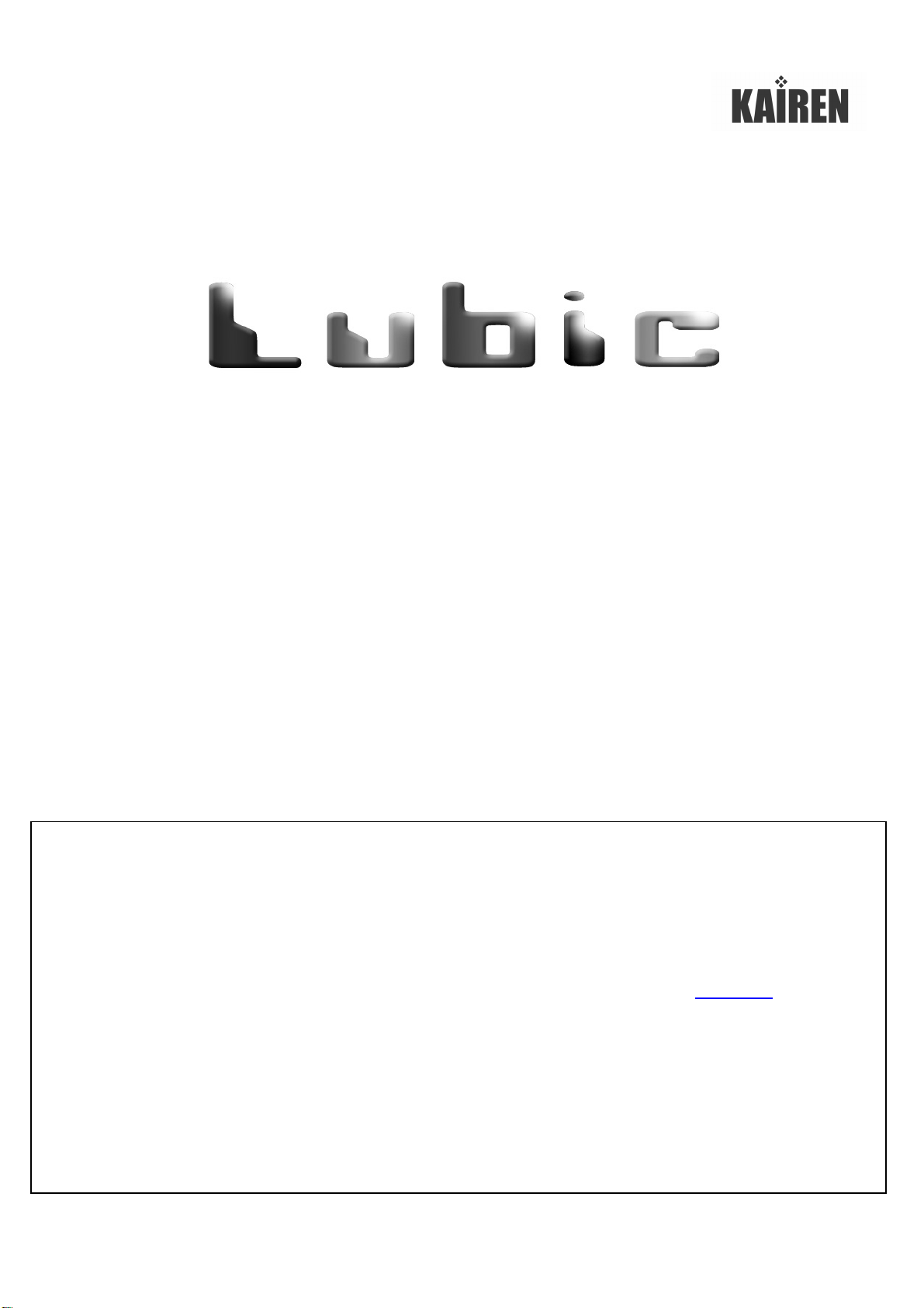
[Notes in advance to assembly work]
●Please read this manual carefully before starting an assembly work.
●Please check that all contents are all lined up. * Refer to the “Package Content List”.
If anything is missing, please contact to the support desk described on the cover page.
●Pleasemount the fixing brackets on the acrylic panels before use. Otherwise, the panels may be damaged if the brackets were
mounted after assembly.
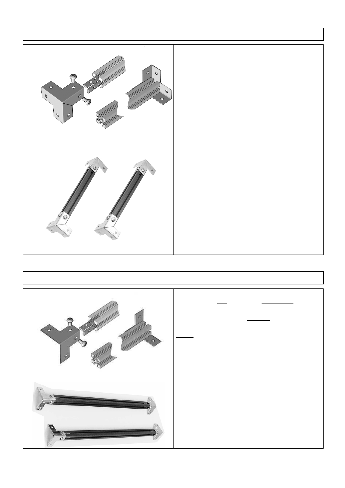
[Notes during assembly work]
●Please work at horizontal and well-balanced place.
●Please wear the attached cotton gloves while working to prevent yourself from being hurt or prevent acrylic panel from being dirty.
●Please conduct work with following the work procedures. Incorrect process may lead to the potential cause of damages or
accidents.
●Please be careful not to scratch any surrounding furniture with frames or metallic material.
●Preparation of cross slot screwdriver and 6mm angle nut spinner is required for assembling the LUBIC BASIC kit.
●All accessories attached to this product are processed into the size that fits to the finished product created by following the work
procedures described in the instruction manual.
Please be careful with the size when assembling in the different work procedure, extension and remodeling.
●Protection film is coated on the metal fittings or acrylic panels. Please remove the film upon use.
●Please be very careful with the direct contact between frames or metal fittings and acrylic panels. It may lead to the potential
cause of damages or corruptions.
●Please keep the used tools or unused parts out of the reach of children after work.
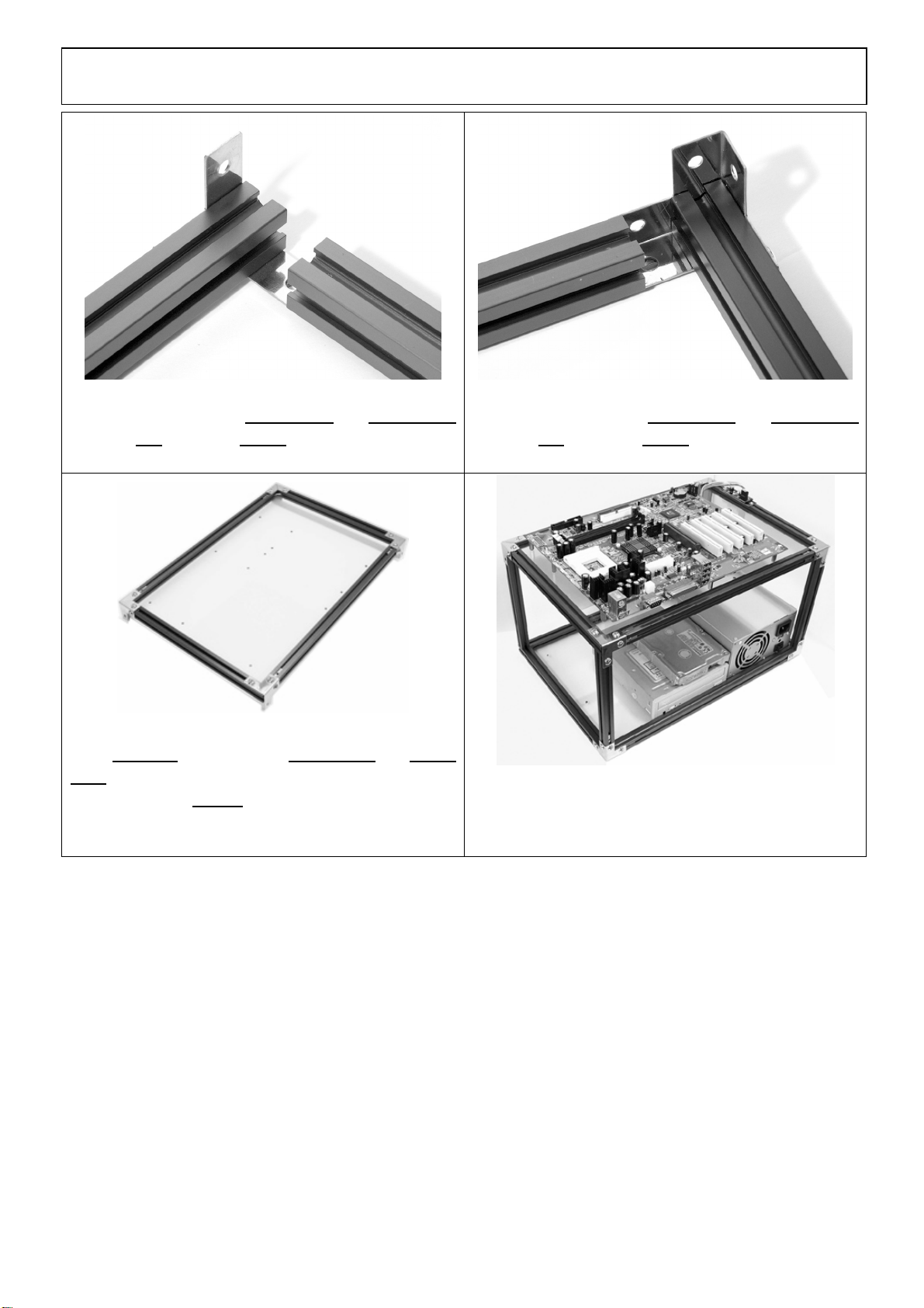
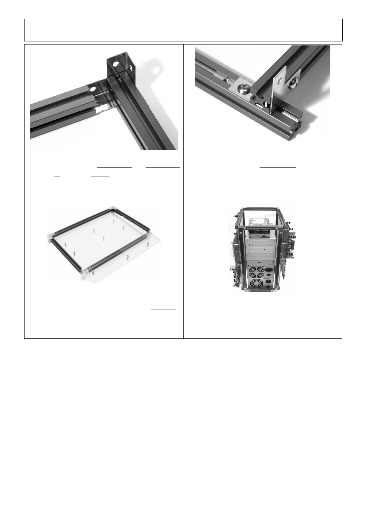
[Installation Part]
Mounting screws on ACMB-AO.
ACMB-AO is an acrylic panel compatible with ATX, Micro-ATX, FLEX-ATX, Mini-ITX.
As spacer screws are not mounted on this panel upon product purchase, spacer screw mounting work is required.
Please use enclosed “nut spinner”for mounting spacer screws.

3
[Notice]
* Protection film is coated on the acrylic panels. Please remove the film upon use.
* If mounted on the incorrect screw holes, it may lead to the cause of short-circuit on the motherboard.
* Please mount after placing motherboard on the acrylic panels and checking the position of screw holes.
* When Dual Motherboard is not used, please mount the spacer screws only on a single plane.
* Once the fixed spacer screws are removed, reinstallation is disabled. Please pay the closest attention upon fixing them.
[Basic Assembly Process]
Insert necessary number of 3S into the frame
grooves.Fix CAPs with SC6M4.
The required tools refers to the ones with “”(underline).
Refer to [Package Content List] for details.
I/O Panel Side

4
- Fabrication Manual -
A Type: Acrylic Panel Fixing Type B Type: Acrylic Panel Sliding Type
By creating planes in either Aor B type, 3 patterns of simple case creation described below are enabled.
“Standard Type”“Removable Motherboard Type”“Dual Motherboard Type”
A+A A+B B+B
This is created with combining A+A
type. 4 sides of the acrylic panel are
created by fixing panels around.
This type is recommended for the
users who wish to conduct no
replacements.
By combining A +B type, plug in and out of
themotherboard is enabled. This is the most
popular creation pattern for Basic series. As
the replacement of motherboard is enabled
easily, this is recommended for the users
who wish to put emphasis on the
maintenance.
This is a double-sided motherboard for
power users, created by combining
B+B type. This perfectly suits to the
narrow places with using 2 units of
PCs.
*When using 2 units of motherboards,
“LUBIC-SWR2”switch is required
separately.
[Work Procedure Overview]
1.As a preparation for plane creation, mount CAP, CAP-EX on 384mm frame.
2.Connect CAP mounted 384mm frame created in 1. above, CAP-EX mounted 384mm frame and 256mm frame together.
3.Complete plane creation.
4.Build a cubic with connecting the created planes.

5
[Step1-1 Work Descriptions: Mount CAP on 384mm frame]
[Step1-1]
Insert “3S”into 384mm frame as shown on the left diagram.
Apply 384mm frame deeply into the “CAP”and fix it with
“SC6M4 Screws”.
* Fix screws so as to face the slit part of the CAP in the same
planes. It will be faced at the top plane in the latter work.
(Refer to the left diagram).
Mount “CAP”on both sides of 384mm frame.
Create 2 pairs of the same parts.
[Step1-2 Work Descriptions: Mount CAP-EX on 384mm frame]
[Step1-2]
Insert 2 pieces of “3S”into the rail of 384mm frame.
Decide the place for mounting “CAP-EX”.
Adjust the end of frame andthe end of CAP-EX, and fix it with
SC6M4.
Mount it without “3S”being protruded from the frame.
Mount “CAP-EX”on both sides of 384mm frame similarly.
Create 2 pairs of the same parts.
【Parts Used】384mm frame x 2 pieces, CAP-EX x 4 pieces, 3S x 8 pieces, SC6M4 x 8 pieces
【Parts Used】384mm frame x 2 pieces, CAP x 4 pieces, 3Sx 8 pieces, SC6M4 x 8 pieces

6
[Step2 Work Descriptions: Create planes preventing acrylic from sliding-【A Type】Creation-]
[Step2-1]
Connect CAP-EX attached 384mm frame and 256mm frame
with using “3S”and fix with SC6M4.
Create other one similarly.
[Step2-2]
Connect CAP-EX attached 384mm frame and 256mm frame
with using “3S”and fix with SC6M4.
Create other one similarly.
[Completion]
Set in ACMB-AO in the groove of 384mm frame and 256mm
frame, and then fix 4 corners.
Now the plane with ACP-A3 completely fixed is created.
The created plane is hereafter called 【A Type】in the following
description.
[Supplementation]
By creating 2 sheets of 【A Type】, “Standard Type”is now
completed described in the 【Completion Examples】at the
end of this document.
【Parts Used】CAP-EX mounted 384mm frame x 1 piece, CAP mounted 384mm frame x 1 piece, 256mm frame x 2 pieces,
ACMB-AO x 1 piece, 3S x6 pieces, SC6M4 x6 pieces
256mm frame
↓384mm frame
←
256mm frame
↓
384mm frame

7
[Step3 Work Descriptions: Create planes preventing acrylic from sliding-【B Type】Creation-]
[Step3-1]
Connect CAP-EX attached 384mm frame and 256mm frame
with using 3S and fix with SC6M4.
Create other one similarly.
[Step3-2]
Connect CAP-EX attached 384mm frame with the parts
created in [Step3-1]. At this time, connect them with proving a
height difference. Leave a space for placing a single frame
as shown in the picture above.
Create other one similarly.
[Completion]
Although all 4 corners are fixed, plug in and out of ACMV-AO
is enabled as there is a height difference.
The created plane is hereafter called 【B Type】in the
following description.
[Supplementation]
By creating 2 sheets of 【B Type】, “Dual Motherboard Type”
is now completed described in the 【Completion Examples】at
the end of this document.
【Parts Used】CAP-EX mounted 384mm frame x 1 piece, CAP mounted 384mm frame x 1 piece, 256mm frame x 2 pieces,
ACMB-AO x 1 piece, 3S x6 pieces, SC6M4 x6 pieces
256mm frame
↓384mm frame
←
384mm frame
→
↑
256mm frame

8
[Step4 Work Descriptions: Create height by using 4 pieces of 192mm frames]
[Step4-1]
(Picture above refers to Atype, but the same as B type)
Place one plane created, either A or B type, as bottom plane
and fix 192mm frame on CAP and CAP-EX at 4 corners.
[Completion]
Fix 192mm frame on 4 corners for completion.
【Parts Used】Aor B type x 1 plane, 192mm frame x 4 sheets, 3S x 6 pieces, SC6M4 x 6 pieces

9
[Step5 Work Descriptions: Create a cubic and complete]
[Completion]
Cover the rest of the planes on top of the plane created previously at[Work Descriptions: Create height by using 4 pieces of
192mm frames]
Mount switches at random places and fix 4 corners with 3S and SC6M4 for completion.
By combiningA + B type as shown in the above picture, “Removable Motherboard Type”is now completed described in the
【Completion Examples】at the end of this document.
【Parts Used】Aor B type x 1 plane, plane with height created by using 192mm frames, SWR2 x 1 piece, 3S x8 pieces,
SC6M4
x
6
pieces
・
SC6M3
x
2
pieces

10
【Completion Examples 】
“Removable Motherboard Type”
By combining A+B type, plug in and out of
motherboard is enabled. This is the most
popular fabrication pattern of Basic series.
As the replacement of motherboard is enabled
easily, this is recommended for the users who
wish to put emphasis on the maintenance.
“Standard Type”
This is created with combining A+A type. 4
sides of the acrylic panel are created by fixing
panels around.
This type is recommended for the users who
wish to conduct no replacements.
“Dual Motherboard Type”
This is a double-sided motherboard for power
users, fabricated by combining B+B type. This
perfectly suits to the narrow places with using 2
units of PCs.
*When activating 2 units of motherboards at the
same time, “LUBIC-SWR2”switch is required
separately.

11