Kamesan KS-6002 User manual

KS-6002
EQ / Compressor
Operating manual
EQ
POWER
EQ4EQ3EQ2
EQ1
ON
COMP
ON
ON
ON
COMP
ON
L
K
N
I
L
K
N
I
+12
-12
200 15K12K3.2K
+12
-12
EQ
ON
+12
-12
200 15K12K3.2K
+12
-12
EQ
ON
+12
-12
200 15K12K3.2K
+12
-12
EQ
ON
+12
-12
200 15K12K3.2K
+12
-12


3
KS-6002 EQ Compressor
Thank you for your purchase of the Kamesan KS -6002 integrat-
ed 4-channel EQ unit and compressor, which integrates with
Kamesan mixer units such as the KS-342 and extends their
capabilities.
The key features of this unit include switchable 2-band EQ on
each channel, as well as switchable compression on each chan-
nel, which can be linked between adjacent channels for stereo
operations.
No external power supply is needed for the unit—power is
drawn through the integrated connector when it is mounted on
the Kamesan mixer.
NOTE
This unit cannot be used in standalone operations. It is only
suitable for use with other Kamesan products, such as the KS-
342 or KS-6001 mixers. Use or attempted use with any other
unit will invalidate the warranty.
Notes and warnings
Follow the common-sense precautions below:
Do not allow liquids to come into contact with the unit
or be spilled inside. Should this occur, re, damage or
malfunction may result.
Make sure that no metal objects or easily inammable
substances inadvertently get inside the unit through holes
or slots. Should this occur, re, the unit may become
damaged or start to behave erratically.
Do not attempt to disassemble the unit, as damage or
malfunction may result.
Notes on the Operating Environment
Avoid using this unit in places with high heat or high humid-
ity as damage or malfunction may result. When using in an
exceptionally cold environment, battery service life may be
shortened, and there may be a drop in performance. If at all
possible, use this unit in the temperature range as indicated in
the specications.
When connecting this unit to external devices, be sure to read
all related operation manuals and connect the devices correctly
to each other. If there are mistakes in the connections, it is pos-

4
KS-6002 EQ Compressor
sible that either the KS-6002 or the other unit(s) will be dam-
aged.
In the event that smoke or odors come from the unit, turn off
the power and remove all batteries and external power supply
sources at once. Contact your dealer or service representative.
In the event of damage or injury caused by accidents, improper
operation or functioning, the proper course of action shall be
determined according to our service regulations. Please note
that we cannot be responsible in any way for any loss of pre-re-
corded material.
Side view
+
-
+
-
+
-
+
-
Unit release
lever THRESHOLD
LEVEL controls
The KS-6002 unit has the following features when viewed from
the left side:
Unit release lever: There is a corresponding lever on the right
side of the unit. Slide these levers to the RELE. position when
attaching and detaching the KS -6002 to and from another unit
mounted above the KS-6002 (e.g. a KS -6001 sub-mixer). Leave
this lever in the LOCK position when the KS-6002 is attached to
the KS-6001 or the other unit.
When using the KS-6002 with the KS -342 or another unit at-
tached below the KS-6002 using the bottom connectors, use
the unit release levers of the other unit, not those of the KS -
6002, to attach and detach the KS-6002.
NOTE
The KS-6002 always should be placed above at least one other
Kamesan unit when tted in a stack of such units. Although
some such units have retractable connectors, the KS-6002 lower
connector cannot retract, and there is therefore a danger of
damage if it is left protruding below the unit. You should also note
that there is also a plate on the top surface of the KS-6002 which
can be removed and used to connect the KS-6002 to other

5
KS-6002 EQ Compressor
equipment (in which case, the KS-6002 becomes the “jam in the
sandwich” between the KS-342 and another unit such as the KS-
6001 sub-mixer).
THRESHOLD LEVEL: Use these controls to set the individual
threshold levels of the four compressor units for each channel
of the mixer connected to the KS -6002.
Since optimum setting levels will vary according to the nature
of the material, there is no standard setting of the threshold lev-
el. Accordingly, you should nd the optimum setting point while
auditioning the signal you will be recording or broadcasting).
Note that the compression takes place post-EQ, so you should
probably make the EQ settings before adjusting the threshold
of the compressors.
Basically, you should make the setting when a slightly higher
than normal level is encountered, and when the compression
indicator of the channel (on the front panel) starts to turn or-
ange. When the knob is in the 12 o’clock position, the threshold
level is 8 dB higher than the standard 0 dB level.
The threshold can be set between 0 dB and +12 dB. The attack
time is xed at 3 ms, and the release time at 300 ms. Neither of
these values can be altered.
Front Panel Features
The front panel is where most of the action on the KS - 6002
takes place.
EQ
POWER
EQ4EQ3EQ2
EQ1
ON
COMP
ON
ON
ON
COMP
ON
L
K
N
I
L
K
N
I
+12
-12
200 15K12K3.2K
+12
-12
EQ
ON
+12
-12
200 15K12K3.2K
+12
-12
EQ
ON
+12
-12
200 15K12K3.2K
+12
-12
EQ
ON
+12
-12
200 15K12K3.2K
+12
-12
Equalizer level controls
(x 4)
Equalizer band
frequency controls
(x 4)
EQ ON
switch (x 4)
Compressor ON
switch (x 4)
Compressor
indicator (x 4)
Compressor link
switch (x 2)
Power indicator
(x 1)
Equalizer level controls (per channel) Each channel has two
equalizer level controls, which allow signals in the selected fre-

6
KS-6002 EQ Compressor
quencies to be cut or boosted by up to 12 dB. These controls
are center-detented, with a “click”, so that it is easy for you to
tell, even without looking, when a band is attened.
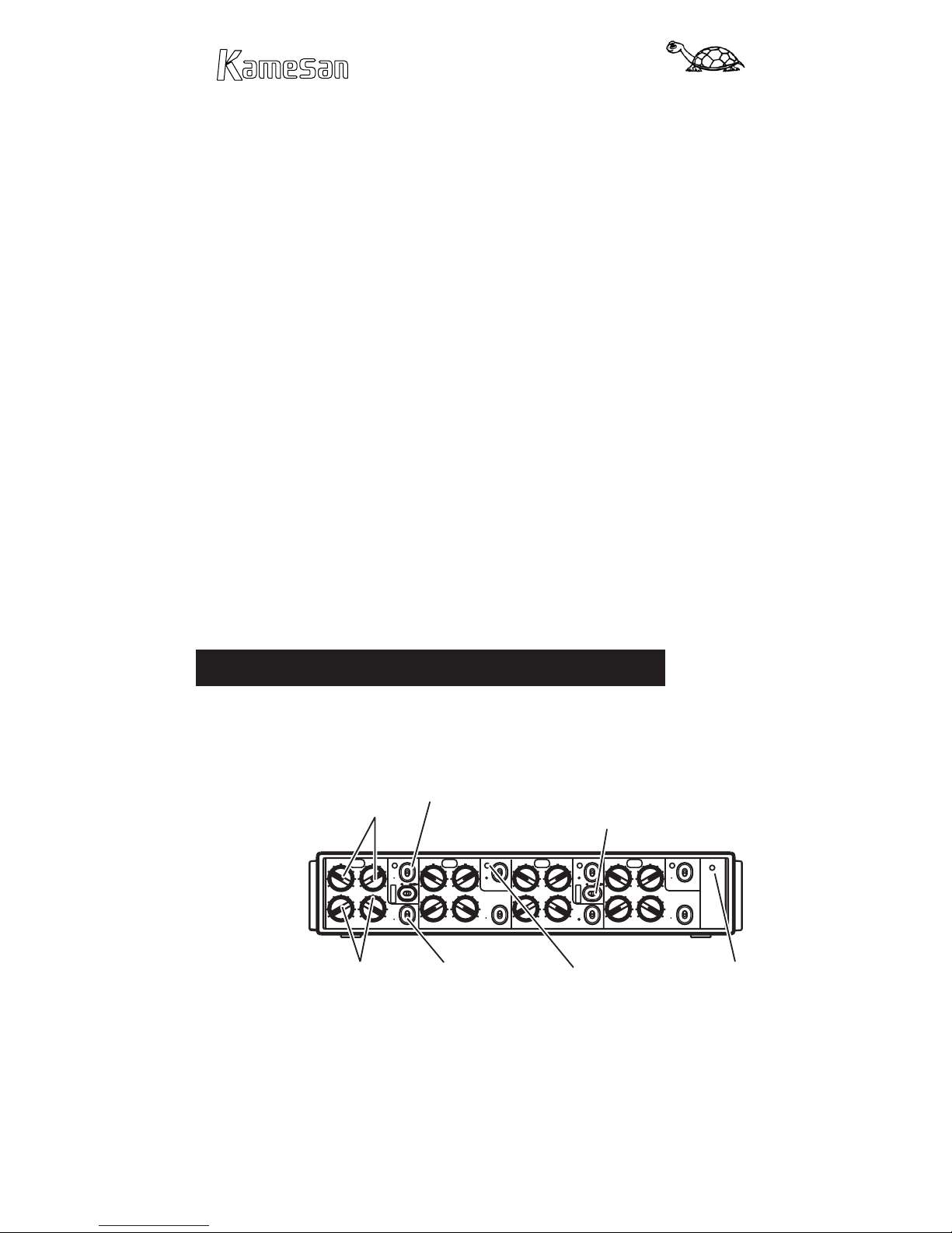
Equalizer band frequency select controls (per channel)
Each channel has two controls allowing you to set the center
frequency of each band. The low center frequency can be set
between 200 Hz and 3.2 kHz. The high center frequency can be
set between 1.2 kHz and 15 kHz.
EQ ON switch (per channel) Each channel’s EQ circuit can
be switched into (switch is up) and out of (switch is down) the
signal path using this switch.
Compressor ON switch (per channel) Each channel’s com-
pressor can be switched into (switch is up) or out of (switch is
down) of the signal path using this switch.
Compressor indicator (per channel) These indicators light
when the compressor is switched into the signal path and the
input signal exceed the threshold (that is, the compressor is in
operation).
Compressor LINK switch (per channel pair) Links odd- and
even-numbered channels’ compressors (1-2, and 3-4), so that
when a signal is received at either channel of the pair that goes
above the threshold for that channel, both channels’ compres-
sors are triggered together.
Power indicator (only one) Shows that the equipment pow-
ering the KS-6002 is switched on and supplying power to the
KS-6002.
Note that the KS-6002 does not have its own power switch.
Power is supplied only through the connector linking the KS-
6002 to the other unit.
Also note that when a signal is passed through the KS - 6002
with both EQ and compression active, battery consumption on
the “host” unit is about 1.5 times that when no signal is being
passed through. Equalization does not use battery power to a
signicant degree, but if you wish to extend the battery life of
the “host” unit, turn the compression off for all channels where
it is not needed.

7
KS-6002 EQ Compressor
Specications, etc.
Compression performance
The graph below shows the output level relative to various input
levels with the compressor enabled, and the threshold set to
different values.
Output level
(relative to nominal)
Input level
(relative to nominal)
Threshold
level
+
Nominal
level
Signal ow within a channel with the KS-342

8
KS-6002 EQ Compressor
Specications
Equalizer
Equalizer type 2-band, peaking type, sweepable fre-
quency
Center frequency ranges LOW 200 Hz to 3.2 kHz,
HIGH 1.2 kHz to 15 kHz
Cut and boost ±12 dB
Compressor
Threshold level Settable from 0 dB through +12 dB
Attack time (xed) 3 ms
Release time (xed) 300 ms
Ratio (xed) 2:1
Audio performance gures (when used with KS-342)
Frequency response 50 Hz to 15 kHz (< ±1.0 dB)
Signal-to-noise ratio (equalizer and
compressor both ON)
MIC –70 > 55 dB (30 kHz LPF/RMS)
LINE +4 > 66 dB (30 kHz LPF/RMS)
Total Harmonic Distortion LINE < 0.5% (50 Hz to 15 kHz, nominal lev-
el, compressor off)
MONI < 0.5% (50 Hz to 15 kHz, nominal
level)
Physical, etc. specications (when used with KS -342)
Power consumption 140 mA (with EQ and compressor
both ON)
Battery life when used with KS-342 > 2 hours (manganese)
> 3 hours (alkaline)
> 6 hours (with NP-1 pack)
Dimensions (w x d x h) 215 x 170 x 40 (mm)
8.5 x 6.7 x 1.6 (in)
Weight 800 g (1.8 lbs)

9
KS-6002 EQ Compressor
Block diagram
EXT I/O TALLY (MIX)
EXT I/O TALLY (INS)
ch 2 SWEEP EQ
ch 3 SWEEP EQ
ch 4 SWEEP EQ
ch 1 SWEEP EQ
FROM CH1 INS OUT
FROM CH2 INS OUT
FROM CH3 INS OUT
FROM CH4 INS OUT
TX25-40P-6ST-H1
TO CH1 INS IN
TO CH2 INS IN
TO CH3 INS IN
TO CH4 INS IN
CH1 INS.OUT
CH2 INS.OUT
CH3 INS.OUT
CH4 INS.OUT
(to SS342)
POWER IND
PFL TALLY
1-2 LINK
3-4 LINK
EXT.I/O
INS I/O
MONI OUT
COMP TH
COMP TH
COMP TH
COMP TH
EXT.I/O
EXT I/O
MIX OUT
MIX IN
AUX IN
PFL IN
E Q
E Q
E Q
E Q
POWER
P-48V
PASS
HIGH
PASS
HIGH
PASS
HIGH
PASS
HIGH
CONT
PASS
CONT
PASS
CONT
PASS
CONT
PASS
LOW
LOW
LOW
LOW
REG
VCA
VCA
VCA
VCA
ON
ON
ON
ON
+B
VC
GR
BA
ON
GR
BA
ON
GR
BA
ON
GR
BA
ON
( 200 3.2KHz ) ( 1.2 15KHz )
( 12dB )
( 12dB )
( 12dB )
( 12dB )

10
KS-6002 EQ Compressor
About Kamesan
Sigma Systems Engineering was started in 1972 to develop and design
professional mixers for studio and remote broadcast applications.
Today, following the “slow and steady” principle of the tortoise, we
have built up our sales and our reputation to the extent that we now
enjoy 95% of the Japanese portable mixer market.
We have concentrated on two or three main areas in our design philos-
ophy: compactness, in an industry which was traditionally dominated
by large, heavy equipment; ease of use, since time is always of the es-
sence in the environments where our products are used; and quality,
to match the needs that today’s broadcasters require.
Our head ofce is in Shinjuku, Tokyo, and as a small company, we are
happy to listen to the ideas for product improvement suggested by you,
the customers and users of our equipment.
Making steady progress (like a tortoise, but maybe a little faster!), we
hope to meet your requirements, now and in the future.
Visit both of our Web sites at http://www.kamesan.co.jp and
http://www.kamesan.info in order to nd out more about what we’re
doing, and to let us know what you are doing with Kamesan prod-
ucts.


Sigma Systems Engineering Co. Ltd.
3-5-2 Okubo
Shinjuku-ku
Tokyo 169-0072
JAPAN
Tel: +81 3 3204 2611
Fax: +81 3 3204 2250
e-mail: sales@kamesan.co.jp
Table of contents
Popular Stereo Equalizer manuals by other brands

Lindell Audio
Lindell Audio TE-100 user manual

SPL
SPL Parametric Equalizer owner's manual

Rane
Rane MPE 14 Operating and service manual

Accuphase
Accuphase AD-2800 instruction manual

Behringer
Behringer FEEDBACK DESTROYER FBQ1000 quick start guide

MCLaren Sound Systems
MCLaren Sound Systems MLQ-750 Owner's manual and installation guide