manuals.online logo
Brands
  1. Home
  2. •
  3. Brands
  4. •
  5. Technics
  6. •
  7. Stereo Equalizer
  8. •
  9. Technics SH-8066 User manual

Technics SH-8066 User manual

Technics
Stereo Graphic Equalizer
SH-8066
OPERATING INSTRUCTIONS
Before o pera
tin
g
thi
s
unit
, pl ease read
th
ese inst
ruc
ti
ons
co
mpl
etely.
Technics. The science of sound. Our name repre-
sents over 100 high quality audio products,
in
every
price range.
From our revolutionary direct-drive turntables to our
highly acclaimed linear-phase speakers, Technics
quality and value have become almost legendary
among audio enthusiasts.
Our truly complete selection of turntables (including
belt-drive, direct-drive, and quartz-locked models
with varying degrees of automation) now includes
an
exciting line of linear tracking turntables with
zero tracking error. Another innovation, direct-drive
cassette decks, is available
in
both slim and micro
formats.
In
fact, with Technics micro series, you can
assemble
an
entire system of the highest quality
!cONTENTS
•ACCESSORIES . . . . . . . . . . . . . . . . . . . . . . . . . . . . . . 2
•PRODUCT SERVICE . . . . . . . . . . . . . . . . . . . . . . . . . . 2
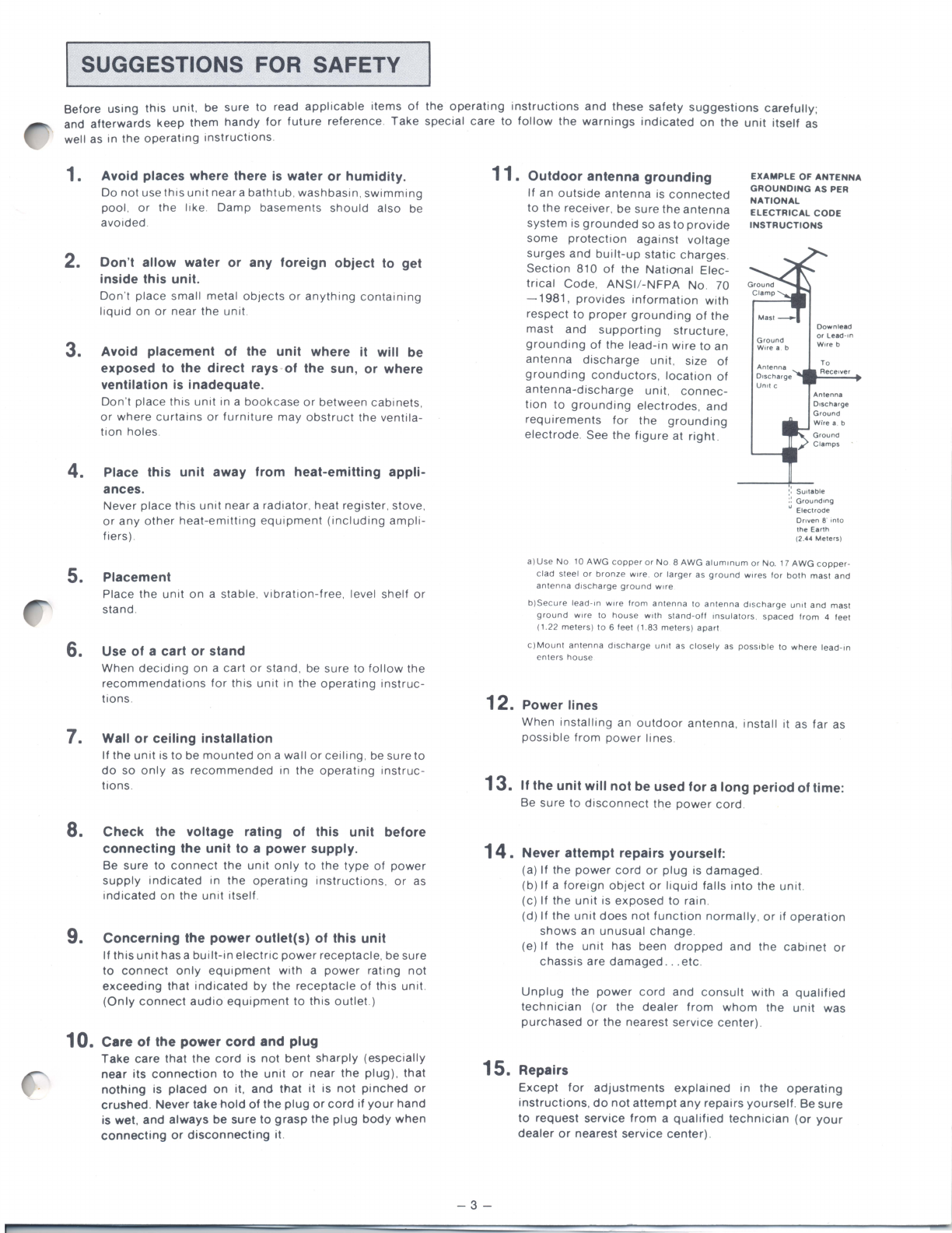
•SUGGESTIONS FOR SAFETY . . . . . . . . . . . . . . . . 3
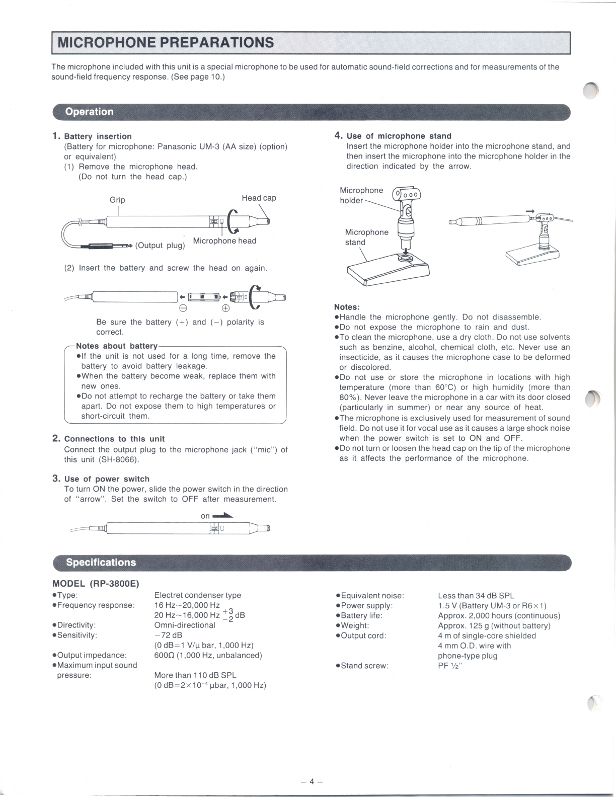
•MICROPHONE PREPARATIONS . . . . . . . . . . . . . . 4
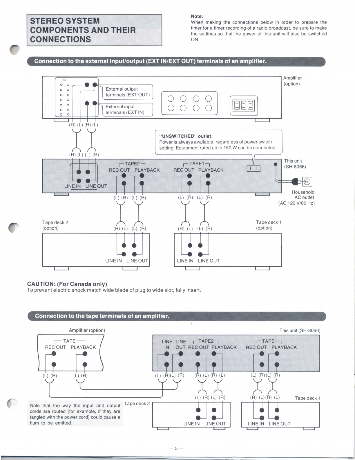
•STEREO SYSTEM COMPONENTS AND THEIR
CONNECTIONS . . . . . . . . . . . . . . . . . . . . . . . . . . . . . . 5
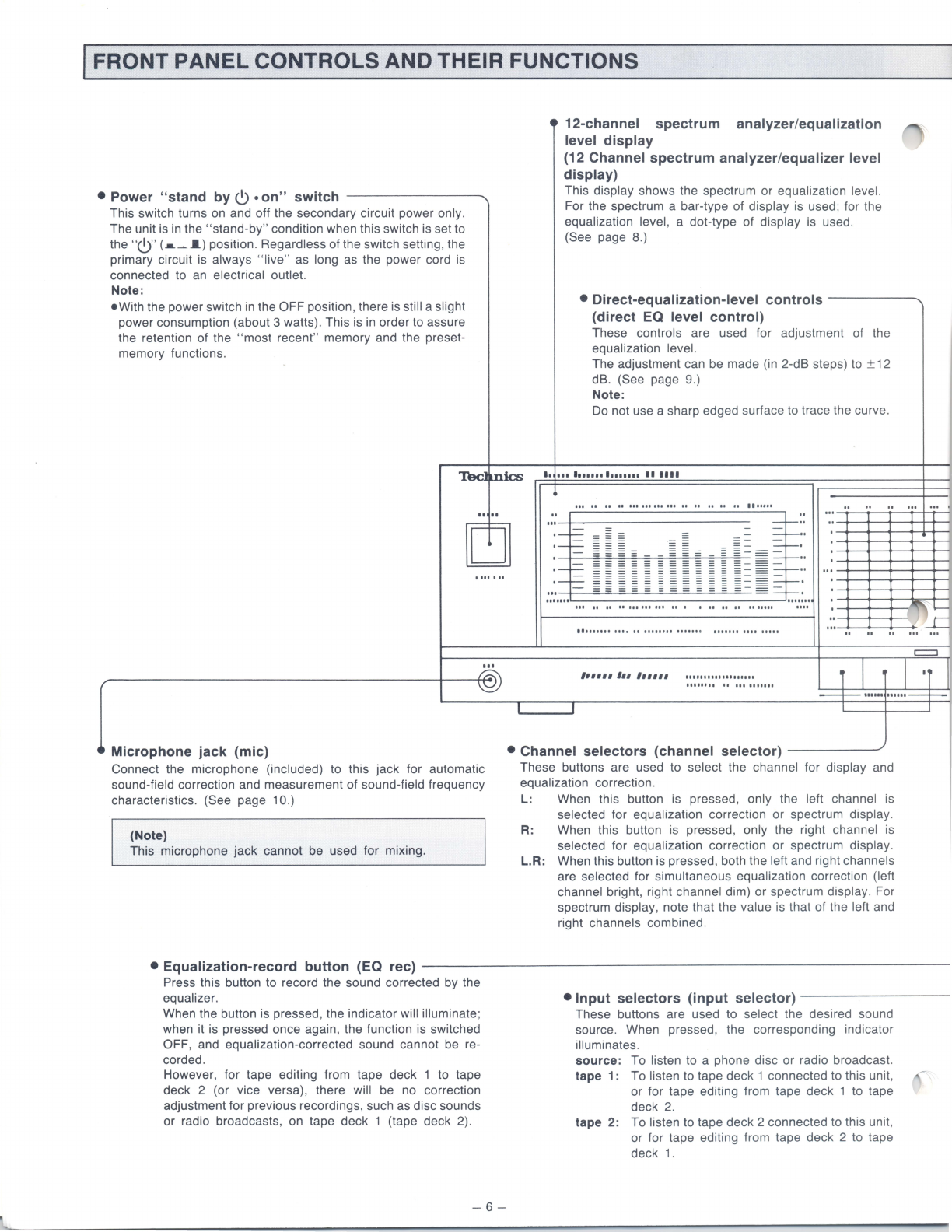
•FRONT PANEL CONTROLS AND THEIR
FUNCTIONS . . . . . . . . . . . . . . . . . . . . . . . . . . . . . . . . 6
•DISPLAY
. . . . . . . . . . . . . . . . . . . . . . . . . . . . . . . . . . . . 8
•OPERATION.......
.
.. ..
...
.
...
..........
.
....
9
•ACTUAL
APPLICATION TO MUSICAL
PERFORMANCE . . . . . . . . . . . . . . . . . . . . . . . . . . . . 14
•EXAMPLES
OF
APPLICATIONS UTILIZING
THE SH-8066 FUNCTIONS . . . . . . . . . . . . . . . . . . . . 15
•TROUBLESHOOTING GUIDE . . . . . . . . . . . . . . . . . .
C2
•TECHNICAL SPECIFICATIONS . . . . . . . . . . . . . . . .
C2
•MAINTENANCE OF EXTERNAL SURFACES . . . .
C2
with truly compact dimensions. And our receivers,
which combine new class-A amplification with
quartz-synthesizer tuning, have created tremen-
dous excitement among reviewers and customers
alike.
Amplifiers, tuners, headphones, microphones, car-
tridges, open reel decks, sound
processors-we
are
proud of all our high quality equipment, and
we
are
constantly seeking to improve our products
in
terms
of performance and handling ease.
In
addition , our
confidence in the reliability of our merchandise
(demonstrated by our warranties) and the reasons
for our enormous and rapid growth become obvious.
A
ACCESSORIES
Stereo connection cables 2
Microphone .
...............
.
..
. .
...
....
......
.
..
.
.....
.
Microphone holder
....
. . . .
...
.
..
. . .
...
..
. .
...........
. . .
Microphone stand
...
.
........
.
.....
.
..................
.
PRODUCT SERVICE
•
Warning
concerning
removal
of
covers
This unit should be serviced by qualified te chnicians only. No
service information
is
provided for customers.
Should your "Technic
s"
product ever require servicing , refer to
the Directory of Authorized Service Centers or your franchised
"Technics" dealer for detailed instructions.
•
Location
of
serial
number
You will find the serial number located at the back of the un it.
AA
r---------------------------------------~
CAUTION
The lightning flash with arrowhead symbol ,
within
an
equilateral triangle,
is
intended to alert
the user to the presence of uninsulated
"dangerous voltage" within the product's encl o-
sure that may be of sufficient magnitude to
constitute a risk of electric shock to persons.
CAUTION: TO REDUCE THE RISK OF
ELECTRIC SHOCK, DO NOT
REMOVE SCREWS.
NO USER-SERVICEABLE
PARTS INSIDE.
REFER SERVICING TO QUALIFIED
SERVICE PERSONNEL.
The exclamation point within
an
equilateral
triangle
is
intended to alert the user to the
presence of important operating and main-
tenance (servicing) instructions
in
the literature
accompanying the appliance.
The model number of this product may be found on the back of the unit; and the serial number on the labe l affixed to th e
back of the unit.
You should note the model and serial numbers of this unit in the space provided , and retain this booklet as a permanent
record of your purchase to aid in identification in the event of theft.
MODEL NUMBER: SH-8066 SERIAL NUMBER
:.
__
____
______
__________
_
WARNING:
TO PREVENT FIRE
OR
SHOCK HAZARD,
DO
NOT EXPOSE THIS PRODUCT TO RAIN
OR
MOISTURE.
-2-
SUGGESTIONS FOR SAFETY
Before
using
this
unit,
be
sure
to
read
applicable
items
of
the
operating
instructions
and
these
safety
suggestions
carefully
;
and
afterwards
keep
them
handy
for
future
reference
.
Take
special care
to
follow
the
warnings
indicated
on
the
unit
itself
as
well as
in
the
operating
instructions.
1.
2.
Avoid
places
where
there
is
water
or
humidity.
Do
not
use
this
unit
near a
bathtub
.
washbasin
.
swimming
pool
.
or
the
l1ke.
Damp
basements
should
also
be
avoided
.
Don't
allow
water
or
any
foreign
object
to
get
inside
this
unit.
Don't
place
small
metal
objects
or
anything
containi
ng
liquid
on
or
near
the
unit.
3.
Avoid
placement
of
the
unit
where
it
will
be
exposed
to
the
direct
rays
of
the
sun,
or
where
ventilation
is
inadequate.
Don't
place
this
unit
in
a
bookcase
or
between
cabine
ts,
or
wh
ere
curtains
or
furniture
may
o
bstru
ct
the
ventila-
tion holes.
4. Place
this
unit
away
from
heat-emitting
appli-
ances.
Never
place
this
unit
near
a
radiator
. heat
register
. stove,
or
any
other
heat-emitting
equipment
(including
ampli-
fiers) .
5.
Placement
Place
the
unit
on
a stable.
vibration-free.
level
shelf
or
stand.
6. Use
of
a
cart
or
stand
7.
8.
When
deciding
on
a
cart
or
stand,
be sure
to
follow
the
recommendations
for
this
unit
in
the
operating
instruc-
tions
.
Wall
or
ceiling
installation
If
the
unit
is
to
be
mounted
on
a
wall
or
ceiling
, be
sure
to
do
so
only
as
recommended
in
the
operating
instruc-
tions
.
Check
the
voltage
rating
of
this
unit
before
connecting
the
unit
to
a
power
supply.
Be
sure
to
connect
the
unit
only
to
the
type
of
power
supply
indicated
in
the
operating
instructions
.
or
as
indicated
on
the
unit
itself
.
9.
Concerning
the
power
outlet(s)
of
this
unit
If
this
unit
has
a
built-in
electric
powe
r receptacle,
be
sure
to
connect
only
equipment
with
a
power
rating
not
exceeding
that
indicated
by
the
receptacle
of
this
unit.
(Only
connect
audio
equipment
to
this
outlet.)
10.
Care
of
the
power
cord
and
plug
Take
care
that
the
cord
is
not
bent
sharply
(especially
near
its
connection
to
th
e
unit
or
near
the
plug).
that
nothing
is
placed
on
it,
and
that
it
is
not
pinched
or
crushed
.
Never
take
hold
of
the
plug
or
cord
if
your
hand
is
wet
,
and
always
be
sure
to
grasp
the
plug
body
when
connecting
or
disconnecting
it
.
11.
Outdoor
antenna
grounding
If
an
outside
antenna
is
connected
to
the
receiver
,
be
sure
the
antenna
system
is
grounded
so
as
to
provide
some
protection
against
voltage
surges
and
built-up
static
charges.
Section
810
of
the
National
Elec-
trical
Code
,
ANSI
/-
NFPA
No
. 70
-
1981,
provides
information
with
respect
to
proper
grounding
of
the
mast
and
supporting
structure
,
grounding
of
the
lead-in
wire
to
an
antenna
discharge
unit
. size
of
grounding
conductors,
location
of
antenna-discharge
unit,
co
nnec
-
tion
to
grounding
electrodes,
and
requirements
for
the
grounding
electrode.
See
the
figure
at
right
.
EXAMPLE
OF
ANTENNA
GROUNDING
AS
PER
NATIONAL
ELECTRICAL
CODE
INSTRUCTIONS
::
Su
1
table
~
Ground
1
ng
Elecl
r
ode
Onven a·
1n1o
the
Earth
(2.
44
Meters)
a)
Use
No
10
AWG
copp
er
or
No
8AWG
alumtnum
o r
No
. 17
AWG
c
opper
-
clad
steel
or
bronze
wtre
.
or
larger
as
ground
wtres
lor
both
mas
t
and
antenna
dtscharge
ground
w tre
b )
Sec
u
re
lead
-tn
wtre
from
antenna
to
antenna
dt
s
charge
un
tt
and
mast
ground
wtre
to
house
wtth
stand-off
tnsulators
.
spaced
from
4
feet
(1.22
meters)
to
6
feet
(1
.
83
mete
rs )
apart
c )
Mo
un
t
antenna
dts
charge
un
1t as
closely
as
po
ss tble
to
where
tead
-m
e
nters
hous
e
12.
Power
lines
When
installing
an
outdoor
antenna,
install
it
as
far
as
possible
from
power
lines
.
13.
If
the
unit
will
not
be
used
for
a
long
period
of
time:
Be
sure
to
di
sconnect
the
power
cord.
14.
Never
attempt
repairs
yourself:
(a)
If
the
power
cord
or
plug
is
damaged
.
(b)
If
a
foreign
object
or
liquid
falls
into
the
unit
.
(c)
If
the
unit
is
exposed
to
rain.
(d)
If
the
unit
do
es
not
function
normally,
or
if
opera
tion
shows
an
unusual
c
hang
e.
(e)
If
the
unit
ha
s been
dropped
and
the
cabine
t
or
chassis
are
damaged
...
etc
.
Unplug
the
power
cord
and
co
nsult
with
a
qualified
technician
(or
the
dealer
from
wh
om
the
unit
was
purchased
or
the
neare
st serv
ice
cen
ter).
15.
Repairs
- 3 -
Except
for
adjustments
explained
in
the
operating
instructions,
do
not
attempt
any
repairs
yourself.
Be
sure
to
request
service
from
a
qualified
technician
(or
your
dealer
or
nearest
service
center)
.
MICROPHONE PREPARATIONS
The microphone included with this unit
is
a special microphone to be used for automatic sound-field corrections and for measurements of the
sound-field frequency response. (See page 1 0.)
Operation
1.
Battery insertion
(Battery for microphone: Panasonic UM-3 (AA size) (option)
or equivalent)
(1) Remove the microphone head.
(Do not turn the head cap .)
Grip
Headcap
~~'---'
-----'t*l...L..Lf-~
!·
~
~
..
(Output plug) Microphone head
(2) Insert the battery and screw the head
on
again .
~
.. ro:::JP
..
~~
8
EB
b
Be
sure the battery ( + ) and (- ) polarity
is
correct.
Notes about battery
---
--
-----
--
,
•If
the unit
is
not used for a long time, remove the
battery to avoid battery leakage.
•When
the battery become weak , replace them with
new ones.
•Do
not attempt to recharge the battery or take them
apart. Do not expose them to high temperatures or
short-circuit them .
2. Connections to this unit
Connect the output plug to the microphone jack (" mic" ) of
this unit (SH -8066) .
3. Use of power switch
To turn ON the power, slide the power switch in the direction
of "arrow". Set the switch to OFF after measurement.
Specifications
MODEL (RP-3800E)
•Type
:
•Frequency
response:
• Directivity:
•Sensitivity:
•Output
impedance:
•Maximum
input sound
pressure:
on
...a...
Electret condenser type
16 Hz -20,000 Hz
20 Hz -16,000
Hz
~
~
dB
Omni-directional
-
72dB
(0 dB = 1 V/
11
bar, 1,000 Hz)
6000
(1
,000 Hz , unbalanced)
More than
11
0 dB SPL
(0 dB = 2 x 10⁻⁴
1J.bar
, 1,000 Hz)
-
4-
4. Use of microphone stand
Insert the microphone holder into the microphone stand, and
then insert the microphone into the microphone holder
in
the
direction indicated by the arrow.
Microphone
stand
0
Not
es:
•Handle the microphone gently.
Do
not disassemble.
•
Do
not expose the microphone to
ra
in and dust.
•To clean the microphone, use a dry cloth. Do not use solvents
such as benzine, alcohol , chemical cloth , etc. Never use
an
insecticide, as it causes the microphone case to be deformed
or discolored .
•Do
not use or store the microphone in locations with high
temperature (more than 60°
C)
or high humidity (more than
80%). Never leave the microphone
in
a car with its door closed
(particularly
in
summer) or near any source of heat.
•The microphone is exclusively used for measurement of sound
field.
Do
not use it for vocal use as it causes a large shock noise
when the power switch is set to ON and OFF.
•
Do
not turn or loosen the head cap on the tip of the microphone
as it affects the performance of the microphone.
•Equivalent noise:
•Power supply:
•Battery life:
•Weight:
•Output
cord :
•Stand screw :
Less than 34 dB SPL
1.5 V (Battery UM-3 or
R6
x 1)
Approx. 2,000 hours (continuous)
Approx. 125 g (without battery)
4 m of single-core shielded
4 mm O.
D.
wire with
phone-type plug
PF
'12"
STEREO SYSTEM
COMPONENTS AND THEIR
CONNECTIONS
Note:
When making the connections below in
order
to
prepare the
timer for a timer recording of a radio broadcast,
be
sure
to
make
the settings so that the power
of
this unit will also
be
switched
ON.
Connection
to
the external input/output
(EXT
IN/EXT OUT) terminals
of
an amplifier.
0 -
0 0
0 0
~
n External output J
0 0 terminals
(EXT
OUT)
0 0 0
0 0 nExternal input
0 0 terminals
(EXT
IN)
0 0
L---..J
(R) (L) (R) (L)
XX
(R) (L) (L) (R)
, LINE IN LINE
OUT
Tape
deck
2
(option)
(L) (R) (L) (R)
XX
(R) (L) (L) (R)
LINE IN LINE
OUT
CAUTION~
(For Canada only)
J [ 0 0 0 0
0 0 0 0
"UNSWITCHED" outlet:
l
[1~]
L--..J
Amplifier
(option)
Power is always available, regardless
of
power switch
setting. Equipment rated up to 150 W can be connected.
(L) (R) (L) (R)
X X
(R) (L) (L)
(R
)
LINE IN LINE
OUT
Household
ACoutlet
(AC120V
/
60Hz)
Tape
deck
1
(option)
To prevent electric shock match wide blade of plug to wide slot, fully insert.
Connection
to
the tape terminals of an amplifier.
Amplifier (option) This unit (SH-8066)
r--
TAPE
---,
REC
OUT
PLAYBACK
LINE LINE
rT
APE2-,
rTAPE1-,
IN
OUT
REC
OUT
PLAYBACK
REC
OUT
PLAYBACK
(L) (R) (L) (R) (L) (R)(L) (R) (R) (L) (R) (L)
l._____Y
_
__
-...Jr
y
Note that
the
way
the
input
and
output
Tape
deck
2
cords are routed (for example,
if
they
are
tangled with
the
power
cord) could
cause
a
hum to
be
emitted.
- 5 -
XX
(L) (R) (L) (R)
LINE IN LINE
OUT
(L)
(R)(L)
(R)
XX
(R) (L)(R) (L)
Tape
deck
1
LINE IN LINE
OUT
FRONT PANEL CONTROLS AND THEIR FUNCTIONS
• Power "stand
by
C)
•
on"
switch
---------....
This switch turns on and off the secondary circuit power only.
The unit is in the
"stand-by"
condition when this switch is set to
the
"C)"
(•~
I)
position. Regardless of the switch setting, the
primary circuit is always
"live"
as long as the power cord is
connected to an electrical outlet.
Note:
•With
the power switch in the OFF position, there is still a slight
power consumption (about 3 watts). This is in order to assure
the retention of the
"most
recent" memory and the preset-
memory functions.
12-channel spectrum analyzer/equalization
level display
(12 Channel spectrum analyzer/equalizer level
display)
This display shows the spectrum
or
equalization level.
For the spectrum a bar-type
of
display is used; for the
equalization level, a dot-type of display is used.
(See page 8.)
• Direct-equalization-level controls
--
---
-...
(direct EQ level control)
These controls are used for adjustment of the
equalization level.
The adjustment can be made (in 2-dB steps) to ± 12
dB. (See page 9.)
Note:
Do not use a sharp edged surface to trace the curve.
~mics
•·
..................
••••••
Microphone jack (mic)
Connect the microphone (included) to this jack for automatic
sound-field correction and measurement of sound-field frequency
characteristics. (See page 1 0.)
(Note)
This microphone
jack
cannot be used for mixing.
Ill
U U
II
ltiiiiiiiiU
If
II II
U
II
lltUit
" " "
...
...
.
...
"
...
j~
"
:
!
~
...
" " "
...
1 =
-
-~
::
.~
~~=
=~
=
=
=
.
: - =
:::
= : =
~
~ ~
~ ~
~
~
= =
::
..
:--=-
~
~
~
~
~
~
~
~
~
~
~
~=
~-
:
.......
Ul
II
II
llllltiiUI
II
I
II
U
II
1111111
IIU
lltUII
II
lllo
II
tttnttl
111111
1
11111111111
IIIII
=
,,,,,, ,,, ,,,,,,
..................
. i I I
·r
---+-
······
······--+--
I
• Channel selectors (channel selector) -
----"'
These buttons are used to select the channel for display and
equalization correction.
L:
When this button is pressed, only th e left channel is
selected for equalization correction or spectrum display.
R. When
th1s
button
1s
pressed, only the right channel
is
selected for equalization correction or spectrum display.
L.R:
When this button is pressed, both the left and right channels
are selected for simultaneous equalization correction (left
channel bright, right channel dim)
or
spectrum display. For
spectrum display, note that the value
is
that of the left and
right channels combined.
• Equalization-record button (EQ rec)
--------------
--
-----
-----
----
-
Press this button to record the sound corrected by the
equalizer.
When the button is pressed, the indicator will illuminate;
when it is pressed once again, the function is switched
OFF, and equalization-corrected sound cannot be re-
corded.
However, for tape editing from tape deck 1 to tape
deck 2 (or vice versa), there will be no correction
adjustment for previous recordings, such as disc sounds
or radio broadcasts, on tape deck 1 (tape deck 2).
-6-
• Input selectors (input selector)
------
--
-
These buttons are used to select the desired sound
source. When pressed, the corresponding indicator
illuminates.
source: To listen to a phone disc
or
radio broadcast.
tape 1: To listen to tape deck 1 connected to this unit,
or
for tape editing from tape deck 1 to tape
deck
2.
tape 2: To listen to tape deck 2 connected to this unit,
or
for tape editing from tape deck 2 to tape
deck
1.
Automatic-equalization button (auto EQ)
Press this button for automatic correction of the sound-field . When this
button is pressed , the indicator will illuminate; when the function
is
completed , illumination will stop . If a microphone is not connected , this
button will not function. (See page 1 0
.)
t Lock button (lock)
This button
is
used to lock the direct-equalization level-control function .
When this button
is
pressed, the indicator will illuminate; when it
is
pressed once again, the lock is released .
Preset-memory buttons (preset memory)
These buttons are used to preset the equalization curves into
the memory. After curves have been preset into the memory, it
is
then possible to quickly and easily select the desired curve
by simply pressing the corresponding button.
There are eight memory areas: three are for fixed-equalization-
level memory, and five are for use by the user. (See page 12.)
--+-"""'""""---
=
II II
II
II
111-IIIUIIIUI
I·
--+--+--+-+-+-
~ ·
[!]
-+--+~t-+--+-..
=
=:
("
1:-1
_
......
--=-
.....
-
......
--'
..
--4-
...
-
...
~
=
. I I
.....
II
II
"'f'
I I
I'
= I
=
<c.,-t--+-------e
Equalization button (EQ)
II
lllilll
II
............
.
.........
cu~p
This button
is
used to switch the equalization correction
function
ON
and OFF.
When this button
is
pressed, the indicator will illuminate; when
it
is
pressed once again, the function is switched OFF, and the
equalization function is not applied .
'---_~_
__________
Display mode buttons (display mode)
These buttons are used to select either the display of the
spectrum or of the equalization level.
EQ
level : When this button
is
pressed , the
equalization level is shown
on
the dis-
play.
Equalization-add button
(EQ plus)
spectrum analyzer: When this button
is
pressed , the spec-
trum
is
shown on the display.
Press this button to combine
two or more equalization
curves. (See page 13
.)
Memory button (memory)
To enter
an
equalization curve into the memory,
first press this button, and then, while the indica-
tor
is
flashing (about 4 seconds), press one of the
preset-memory buttons to complete the memori-
zation of the equalization curve. (See page 12.)
Pink-noise button (pink noise
This button can be used to switch
ON
and OFF the
"pink" noise used when measuring the sound-field
frequency response or correcting the sound-field.
If a microphone is not connected, this button will not
function . (See page 1 0.)
-7-
Pink noise
•Pink
noise is used for measurement and
correction of the sound field frequency re-
sponse because it
is
mostly within the audi-
ble range, its energy distribution is uniform ,
and it has a wide frequency band.
•Because
pink noise has large instantaneous
level fluctuations, the display may fluctuate .
DISPLAY
The display can be used to display the spectrum
or
the equalization level.
• For
spectrum
display
(L), (R)
or
(L.R)
OB
+12 - · - ·
*The
"full
range" area on the right side
displays the combined level of all of the
frequency bands.
* If there is no input signal to this unit. The 1st
row (0 dB) of all frequency bands is
displayed.
OB
-30
[spectrum 1
analyzer
• For equalization-level
display
(l)
or
(R)
OB
.,
_
~-~------
--
--
4
-=
=: : : :== -
o--
---
=---=-
-
-=
---
-
a-
..
..
.. .. ..
OB
-
30
-
25
-20
-"
----:-:-c
c:--
:::-=--c:::-~--=---::----=
---:,----,:--
=-:
-0
25 40
63
100 160 250 5
00
l k
2k
4k
8k
16
k
lull
range
rl
EQievel
J
•
For
equalization-level
display
(L.R)
--
-
~~
+
~
:-
_
-
:
_
:_
:--
:
-=-
·
=-
=- -=
-=-=-=-
~
-
OB
_: _: =: =· _
..
: : == =:=:=:= -
-2
0
o- -
--
- -
=-
--
-
05
Left and right
channels
displayed
brightly at the
same position.
- 5
·
1=
1:
:·
::1::·::
1
·""
""
"j
"""
C:
'
p
"
~
12
25
\ 40
63
1
00
16
0
250
500
'x
k 2 k
4
~
8k 16k lui r
ange
-0
Right channel
(dim)"----
Left channel (bright)
AUTOMATIC LEVEL FUNCTION
This unit incorporates a function for automatic adjustment of over-indication
or
under-indication of the spectrum (caused
by
hi
gh
or low
input signal levels), so that the displayed spectrum is always at the central part of the display for easy visibility.
• When
input
level
is
high
OB
.,
OB
-
30
a
~
-
~
=
~
=
~
-
~
=
~
=
~
=
~
::
=
~
=
~
-
~
_ =
:=
~
25
~When
the average value of
•
-::
~
:
~
:
~
:
~
:
~
:
~
:
~
:
~
:
~
:
~
:
~
:
~
=
::-
" the spectrum exceeds this
o _
~
-
;;;. ;;;. ;;;.
;;;
.
;;;
.
;;;
. ;;;. ;;;. ;;;.
;;;
. ;;; ..:
::-
05
level, the overall spectrum is
·
-::
~
:
~
:
~
:
~
:
~
:
~
:
~
:
~
:
~
:
~
:
~
:
~
=
::-
" suppressed by 10 dB.
a
-::
~
:
~
:
~
:
~
:
~
:
~
:
~
:
~
:
~
:
~
:
~
:
~
=
::-
s
~~~~~
~
~~-=~~~=-=-
==
-
o
25 40 6 3 1
00
160 2
50
5
00
lk 2k 4k
Bk
16k
tu
l r
ange
• When
input
level
is
low
OB
+
"
-~-----
-
------
dB
- 30
-==--'
-
=-c
-
=-=---=-·
~
==-
·
~=
=·
--=
=
,__·
~=
,..·
-=-
~-=
~
= -0
25
40
~
1
00
~
2
50
~
lk
~
4k
6k
-
·~~~
When the average value of
the spectrum is less than this
level, the overall spectrum is
raised by 1
0 dB.
~8
~
dB
., _
__
-
dB
-
30
8 - =
=-
25
4 - • - - =
=-2
0
-=
---;;;---;;-
~
-=-=
--
- - - -
05
:
~
~
~
~
~
~
~
~
~
~
~
~
~
~
~
~
~
~
~
~
~
~
~
~
~
~:
-=· =· = · =· = · =-=-= · = · =- = · = -
.::_o
25
40
63
100
160 250 5
00
lk
2k
4k
8k
16 k
tuM
range
*The actual input level is shown
b
y~
the "full range" display at the far
right.
dB
+
"
---------
-
-~-
-
4
~
~
=
~
=
~
:
. :
~
=
~
=
~
=
~
=
~
=
~
=
=-
dB
- 30
-25
-05
e
-
~
-
~
-
~
-
~
-
~
-
~
-
~
-
~-
~
-
~
-
~
-
~
-
_ - 5
- = - =·
=·
= · = - =· =· =· =·
=·
= · = - -
=-
o
25 40
63
1
00
1
60
250
500
1k
2k 4k 8k
16k
tuM
ran{Jf!
I OPERATION
MANUAL CONTROL OF THE EQUALIZATION LEVEL
1 .
Select
the channel(s) to be adjusted.
L:
To adjust the left channel
R:
To adjust the right channel
L.R:
To adjust the left and right channels
2.
"off"------------
Co
(
The stroke of this button has been increased
in
J
order to prevent mis-operation, so they must be
pressed firmly.
"Iechnics
looooo
louooolouuoo
II
1111
...
..
..
..................
..
..
..
..
.....
..
...
............... .
...
..
D "t
~"
...
i
---
•
~··-
...................... "
..
"
.......
,,,,,,,,,,,,,,,
............
.....
..
5.
For
adjustment of the equalization
level.---,.,
Adjustment to ± 12 dB (in 2-dB steps)
is
possible by
pressing the point of intersection of the level and the
frequency where adjustment is desired or by tracing with
a finger.
(If a finger is used, move it slowly, allow
for)
proper operat1on.
nvenient Functions
:-[~~
:
..
ra~
. L:J
__
...
[]
• (Lock button)
----------------------"
"on" Equalization curves can
be
protected.
(
When this button
is
pressed to
("on")
, the direct-equalization-level J
controls will not function, thus protecting
an
equalization curve(s) which
has been set. The pressed position will be illuminated
on
the display,
and
the desired frequency and level value can be easily found .
"off" Frequencies can
be
easily detected and changed.
(
When the lock button is pressed to "off" while the direct-equalization- )
level control
is
being pressed, the level of a frequency can be easily
changed.
-9-
I'
I'
3.
"EQ
level"
I
I
4. "on"
Press the "spectrum analyzer"
button to aurally adjust while
watching the spectrum display.
I OPERATION
BEFORE MEMORIZATION OF EQUALIZATION CURVES
This unit has eight memory areas; five of these are available to
the user, and can be changed ; the other three are preset (fixed)
music curves and cannot be changed.
• Memory areas for the user
•As
many as five pairs (left/right channels) of equalization
curves can be entered into memory areas 1 through
5.
•When
an automatic sound-field correction is made, the
equalization curve is automatically entered in memory area
5.
• Fixed-equalization-level memory areas
Equalization curves which are appropriate to the following
three types of music have already oeen preset to memory
areas 6 through 8, thus making it possible to enjoy music
listening at a touch of a button . (Other equalization curves
cannot be entered into these memory areas.)
MEMORIZATION OF EQUALIZATION CURVES
1 . Set the equalization level.
Memory area 6 (rock)
The level for 63 Hz and 100 Hz is increased
in
order to
emphasize the power of the bass fiddle and bass drum ; in
addition, the level for the range from 4 kHz through 16 kHz
has been increased in order to obtain a characteristic in
which there is a tauter high range and low-range build-up.
Memory area 7 (jazz)
The level for 63 Hz and 100 Hz is increased, and moreover
the level for 4 kHz and 8 kHz is moderately increased ,
in
order to provide a modulated, soft sound.
Memory area 8 (vocal)
The 2-kHz range is increased by 4 dB and the 4-kHz range is
increased by 2 dB; in addition, the 500-Hz range is reduced
by - 4 dB, thus providing a clear characteristic with excellent
vocal emphasis.
2. "on"
(The indicator will flash for about 4 seconds.)
\See
page 9.)
~
~~
-
;:~~:-_
~~
--
~·
~·
~
·
·~·
f I
11
·
~
·
.•.
· ~
·~·
·
·
~
:~
~
+
~
+
1
]~3.Pressone~llie
,
___
. . _.
__
. _
__
_
.;.
-.
• • i I • • i • • • r
LJ
,__
~
~~~:~~~~~:~r
whll•
......
.........
........
.......
.......
.....
.. .. ..
.........
....
..
.....
....
-·
D
~
L::.J the indicator
is
flashing (in step
2)
.
·
1
·
1
~
1~1
::·::
1:
:·:
:1~1
.............
..
....
.
..
..........
..
I~=
,
..
,.,,,.,,
* If two or more entries are made into one memory area, only the
last one will be memorized.
*The memory-add
"EQ
plus" button will not function, even if it is
pressed, while the indicator of the memory button is flashing.
MEMORY RETRIEVAL-OUT
Press the preset-memory button for the equalization curve
you want to retrieve from the memory.
[
The indicator for that button will illuminate, and the display
will instantly change to the retrieved equalization curve.
When a retrieval is made from the memory, if the equalization
button is
OFF
, the indicator for the preset-memory button will
illuminate, and the equalization curve will appear on the
display, but the equalization effect will not be applied .
-12 -
TO CANCEL A MEMORY RETRIEVAL-OUT
Press either a direct-equalization control or a preset-
memory button.
(The indicator for the preset-memory button used to
make
the)
retrieval will stop illumination.
EQUALIZATION ADD (COMBINATION OF FREQUENCY RESPONSES)
It
is
possible to combine (addition of frequency responses)
equalization curves which have already been entered into the
memory areas , or to combine
an
equalization curve which has
already been entered into a memory area with a manually set
equalization curve (see page 9).
•
Combination
of
a
sound-field
correction
curve
(already memorized) and a memorized equaliza-
tion
curve.
[
After flattening the frequency response
by
automatic]
sound-field correction (see page 1
0)
, if this is then
combined with
an
equalization curve entered into the
preset memory, you can then enjoy music which has been
tailored so as to best fit the conditions of the listening
room .
(Automatic sound-field corrected equalization
curve)
Preset-memory button " 5" 1 . Press preset-memory
button
5.
----1·
.-::~~
----------------
-
-
~
c:-1
~
__
.............
..
1·
I
1
·
···-:~
......
:
:.0
1· I
. I'
.
I'
-
~
...::.::::__
..
.........
..
..................
.
2. Press
the
equalization-add
"EO
plus"
button.
(The indicator will flash for about 4
seconds.)
a-
-
25
-
20
_,
-o
25
40
63
100 160
250
500
lk
2k
4k
8k
16k
lui
range
(Equalization curve for added preset memory)
Note that this curve will not appear on the
display.
: I
::·:
: I
.....
I
c::;::J=
3. Press the preset-memory
button
----1
.
~~
----------
--

for
the
curve
to
be added.
08
-
30
-
25
Equalization-add button
(EO plus)
[
Press the preset-memory button while l
the equalization-add "EO plus"
button
is
flashing .
-
0
-
·
~
=
-----
=-
-
--
-
--
-20
-o
25
40
~
100 160 250 500
lk
2k 4k
~
*
luM~nge
(Equalization curve after addition)
The indicators for the two added preset-
---f
.
~~~~:_~:_-:::_:_:_~:_~:_~:_-:::_:_:_~:_~
:_
~
:_
-:::_:_:_~:_~--
-
~~;;1~
memory buttons will illuminate, and the
equalization curve after the addition will
-
25
-
20
appear on the display.
li<
To memorize
the
combined
curve.
Press the memory button , then the preset memory button to
store the new curve.
•
Combination
of
preset
memorized
equalization
curves
1. Press the preset-memory button for one of the equalization
curves to be combined .
2.
Press the equalization-add "EO plus" button.
3. Press the preset-memory for the other equalization curve to
be combined .
-
4 - •
=--
. -
00
8 - D g •
-5
12
-o
25
40
63
100 160
250
500
lk
2k
4k
8k
16k
ruM
range
•
Combination
of
a
manually
set
equalization
curve
and a
preset
memorized
equalization
curve
1. Set the equalization level manually (see page 9
).
2. Press the equalization-add "
EO
plus" button.
3. Press the preset-memory button for th e equalization curve to
be added .
*The combined equalization curve can also be entered into the preset memory (see page 12
).
li<
The memory button will not function if it is pressed while the indicator of the equalization-add "
EO
plus" button
is
flashing .
*
If
equalization curves are combined , the display range and the equalization level of the frequency of each
is
a maximum of ± 12 dB.
-13-
I ACT
UAL
APPLICATION TO MUSICAL PERFORMANCE
•
Connection
of
the
input/output
terminals
(LINE IN/LINE OUT)
of
this
unit
to
the
external
input/output
terminals
(EXT IN/EXT OUT)
of
an
amplifier.
1.Reduce the
amplifier's
volume
control
setting
to
minimum
and
switch
ON
the
power
switch.
~·Tone
controls:
Center
position.
'I8ocbnics
....
..
.....
...
~
........
•• •••
0 0
......
o
..
..
..
o
..
."
Ef'""
...
0'
..
I = =
...
8.:
:
...
~
..
....
~
1
=9
1
""'·
1
"'"
1""1"
"1"
l_
__
_ u
II""'
! IH
II
'""
3.
Input
selectors:
Select the
sound
source.
0
L_____j
Amplifier
(option)
8. Begin the sound source
(phonodisc
, radio
broadcast, etc.) and then
adjust the amplifier's
volume level accordingly.
9.
Adjust
tone
quality
as desired.
(See page 9.)
....
..!..
,.,,,,.,,,,.
,
4. Select
the
channel(s)
to
be----/
corrected
or
displayed.
(See page 9.)
*Switch ON if a recording of the corrected sound
is
to
be made.
(Note that this button cannot be switched ON if the )
equalization button is OFF.
5.Select
the
sound
source.____.-
(See page 6.)
This unit
(SH-8066)
7.
"on"
L
6.
"EQ
level"
r-
When
the
power
switch
is
switched
OFF-----.,
Regardless of the setting of the input selectors, the
input and output terminals of this unit will be directly
connected (electrically) , and equipment connected to
the amplifier (disc player, tuner, etc.) can be heard.
Note that the power switch must be left ON if the "tape
1" or
"tape
2" input selector is being used. If the power
switch
is
OFF, tape sounds cannot be heard.
•
Connection
of
the
input/output
terminals
(LINE IN/LINE OUT)
of
this
unit
to
the
tape
input/output
terminals
(PLA
YBACK/REC OUT)
of
an
amplifier
(amplifier
operation
changes
from
that
shown
in
the
figure
above
to
that
described
below).
•If
the
amplifier
has
a
recording
mode
selector
and
an
•If
the
amplifier
has
a
tape-monitor
selector
and
an
input
input
selector.
selector
[ (input selector) tape J l (input selector) phono or tuner )
D
000
_OJ,
Dr;
0 D
rohlO
c a a c
--------
0
oo
0 0
0
11111111
000
~
1\
I \
[ (rec selector) phono or tuner [ (tape monitor) tape )
-14-
•
EXAMPLES OF APPLICATIONS UTILIZING THE SH-8066 FUNCTIONS
The sound level of the 12 frequency divisions
in
the 25
Hz-16
kHz frequency range can be easily and selectively corrected by
means of the band level control
of
this unit.
1. Complete audio room
correction-including
the correction of
both stereo equipment and room acoustics.
2. Personalized sound quality control.
3. Creating an original tape collection of tapes tailored to your
car stereo, or tapes of live recordings, etc.
4.
Reduction of noise, prevention of howling. These are merely
a few
of
the possibilities that sound quality and room acoustic
correction open up for the serious listener.
•
Correcting
room
acoustics
Each room has its own particular effects on frequency character-
istics. These effects are determined by a number of conditions,
such as rooms size, furnishings, etc.
The 12 separate divisions of the band level control on the
SH-8066 make it possible to selectively correct only the
frequency ranges necessary to suit the conditions of each
listening room .
An
example
of
room
acoustics
correction
In
order to correct the peaks and dips in bass sounds caused by
reflection, reduce the 250
Hz
level 4- 6
dB
and then, raise the
level of sounds below 63 Hz and above 4 kHz slightly.
"
+02
--------------
dB
-
30
-
25
-20
_,
8-
• • •
-5
-
12
-o
25
40
63
100 160 250 500
lk
2k 4k 8k
16k
lull range
•
Cutting
the
noise
from
live
recording
tapes
Live tapes recorded outdoors generally contain popping noises
caused by wind and various other noises from the surrounding
area.
In
order to effectively eliminate wind noise, cut bass
sounds below 63 Hz and raise the level of sounds
in
the 250
Hz-500 Hz range. Then control sounds made by birds, etc
.,
with
a 4 kHz and
or
8 kHz adjustment.
dB
+
02
--------------
·-
·-
"
-
30
- 20
-•5
-
00
- 5
- 12 - 0
25
40
63
100 160
250
500
lk
2k
4k
8k
16k
tu
M range
• Making
tapes
for
car
stereos
Tapes can be made exc
lu
sively for the
li
stening conditions inside
a vehicle. Merely raise the 63 Hz level 4 dB and completely cut
the levels below 40 Hz that are so troublesome for car stereo
reproduction. For medium and low frequencies, centering on the
250
Hz
vicinity, lower the modulating effect by raising the 4
kHz- 8 kHz vicinity by 2- 4 dB.
"
+02
------·------
dB
-
30
·- -25
- o
25
40
63
100 1M
2~
~
lk 2k 4k 8k
1~
fuP~nge
-15-
•
Cutting
noise
from
discs
Noises from warped discs are low frequency noise components.
Lowering the sound level of the 63 Hz vicinity can eliminate
these.
To cut noise
in
old discs, set all direct-equalization level controls
to the "flat" (center) position, and then move them individually to
the
-12
dB position to find the noise component.
Then, working from this clue, cut the noise so as not to
deteriorate the tone quality.
dB
+02--------------
·-
·-
dB
-30
-25
-20
-0
25
40
63
100 160
250
500
lk..
2k
4k
Bk
16k
lu
i range
•
Reducing
tape
hiss
Tape hiss can be effectively reduced by slightly raising the level
of high frequency (above 2 kHz) sounds during tape deck
recording, and then lowering them during playback.
Note:
If sounds above 8 kHz are raised too much, distortion may result
in the tape deck. Prevent this by watching the level meters of the
tape deck and setting the recording levels appropriately.
recording
playback
"
+02
·-
·-
"
+02
·-
·-
-
02
25
<0
25
<0
63
000
,.0
250
500
..
63
•oo
••o
250
500
..
,.
"
..
'"
=---
,.
"
..
.•.
lu
i
range
lui
range
"
-
30
-25
-20
-•5
-00
- o
"
-
30
-
20
_,
-
•o
- 5
- o
I TROUBLESHOOTING GUIDE
Before requesting service for this unit, check the chart below for
a possible cause
of
the problem you are experiencing. Some
simple checks
or
a minor adjustment on
your
part may eliminate
the problem and restore proper operation.
If you are in doubt about some
of
the check points,
or
if the
remedies indicated in the chart
do
not slave the problem, refer to
the directory of Authorized Servicenters (enclosed with this unit)
to locate a convenient servicenter,
or
consult
your
Technics
dealer for instructions.
Problem Probable cause(s) Suggested remedy
No sound
•Incorrect
connection. • Refer to page 5.
•Input
selectors are set to incorrect position.
•Set
them correctly (according to the desired sound
source).
Correction is not possible
at
•The
equalization button is set to the off
•Set
the equalization button to the on position.
recording position.
•The
equalization-record button is switched
•Switch
it ON .
OFF.
Correction is not possible
at
•The
equalization button is set to the off
•Set
the equalization button to the on position.
playback position.
No display appears on the
•The
"EQ level" display-mode button is
•Press
the
"spec
trum analyzer" display-mode
spectrum analyzer. pressed. button.
The spectrum display for the
•The
incorrect channel selector is pressed. • Press the correct one.
desired channel does not
appear.
The
equalization level display
•The
"s
pectrum analyzer" display-mode
•Press
the "EQ level" display-mode button.
does not appear. button is pressed.
The equalization level display
•The
incorrect channel selector is pressed.
•Press
the correct one.
for the desired channel does
not appear.
No pink noise is heard.
•The
microphone is not connected.
•Connect
it.
I TECHNICAL SPECIFICATIONS
(IHF '78)
Frequency response
(center position)
Maximum output
voltage
Rated output voltage
Rated input voltage
Rated total harmonic
distortion
Input sensitivity
Signal-to-noise ratio
Maximum input
voltage
Input impedance
Gain
Band level controls
Center frequency
Compatible microphone
sensitivity
Panasonic Company
10 Hz-50 kHz,
-1
dB
8 V
(1
kHz, THO 0.
03
%)
1 v
1 v
0
.003%
(20Hz
-
20kHz)
1 V output
150mV
above 113
dB
/2 V,
107
dB
/1 V
(IHF,A)
8 V
(1kHz)
22 kO
0 ±
1dB
+
12dB
--
12dB
(2dBstep)
25 Hz,
40
Hz, 63 Hz, 1 00 Hz,
160 Hz,
250
Hz, 500 Hz, 1 kHz,
2kHz,
4kHz
,
8kHz,
16 kHz
above -74
dBV
/
~bar
(1
kHz)
Division of Matsushita Electric
Corporation of America
Matsushita Electric
of
Canada Limited
5770 Ambler Drive,
Mississauga,
Ontario L4W 2T3
One Panasonic Way Secaucus,
New Jersey 07094
Printed
in
Japan
GENERAL
Power supply
Power consumption
(With power switch OFF
Dimensions
(H XW X D)
Weight
AC 120 V
60Hz
17W
3 W)
119x430 x
272mm
(4
11
/16,
X
16
15/ 1
6,
X 1 023
/32
")
3.8 kg (8.4 lb)
MAINTENANCE OF EXTERNAL
SURFACES
To
clean, use a soft
dry
cloth.
If the surfaces are extremely dirty, use a soft cloth , dipped into a
soap and wat
er
or a weak detergent solution.
Wring the cloth well before wiping the unit.
Wipe once again with a soft
dry
cloth.
Never use alcohol, paint thinner, or benzine, nor a chemically
treated cloth to clean this unit.
Such chemicals
may
mar
the finish of
your
unit.
Panasonic Hawaii Inc.
320 Waiakamilo Road , Honolulu,
Hawaii 96817
Panasonic Sales Company,
Division of Matsushita Electric
of Puerto Rico, Inc.
Ave, 65 De lnfanteria, KM 9.7
Victoria Industrial Park
Ca
rolina, Puerto Rico 00630
SQXK5
011
6-1
F0485NO

Other manuals for SH-8066

2

Other Technics Stereo Equalizer manuals

Technics SH-8075 User manual

Technics

Technics SH-8075 User manual

Technics SH-8016 User manual

Technics

Technics SH-8016 User manual

Technics SH-9010 User manual

Technics

Technics SH-9010 User manual

Technics SH-8066 User manual

Technics

Technics SH-8066 User manual

Technics SH-GE50 User manual

Technics

Technics SH-GE50 User manual

Technics SH-GE70 User manual

Technics

Technics SH-GE70 User manual

Technics SH-Z200 User manual

Technics

Technics SH-Z200 User manual

Technics SH-8066 User manual

Technics

Technics SH-8066 User manual

Technics SH-9010 User manual

Technics

Technics SH-9010 User manual

Technics SH-8038 User manual

Technics

Technics SH-8038 User manual

Technics SH-8058 User manual

Technics

Technics SH-8058 User manual

Technics SH-8020 - SERVICE User manual

Technics

Technics SH-8020 - SERVICE User manual

Popular Stereo Equalizer manuals by other brands

Behringer PEQ2200 user manual

Behringer

Behringer PEQ2200 user manual

Iron Age Audioworks LH95 user manual

Iron Age Audioworks

Iron Age Audioworks LH95 user manual

Rane MQ 302L Operator's manual

Rane

Rane MQ 302L Operator's manual

Focusrite Green 2 focus EQ Product information

Focusrite

Focusrite Green 2 focus EQ Product information

Klark Teknik DN27A Operator's manual

Klark Teknik

Klark Teknik DN27A Operator's manual

Rane SSE 35 Operator's manual

Rane

Rane SSE 35 Operator's manual

LA Audio Electronic EQX20 Operation manual

LA Audio Electronic

LA Audio Electronic EQX20 Operation manual

ADC Sound Shaper SS-525X owner's manual

ADC

ADC Sound Shaper SS-525X owner's manual

X4-TECH EQ-1000 Operation manual

X4-TECH

X4-TECH EQ-1000 Operation manual

dbx DriveRack 4800 Specifications

dbx

dbx DriveRack 4800 Specifications

Altec Lansing 8551B Specifications

Altec Lansing

Altec Lansing 8551B Specifications

WorkPro WEQ 231 user manual

WorkPro

WorkPro WEQ 231 user manual

Audio Control EQL owner's manual

Audio Control

Audio Control EQL owner's manual

PowerAcoustik PEQ-50P manual

PowerAcoustik

PowerAcoustik PEQ-50P manual

Prism Sound MASELEC MASTER MEA-2 Operation manual

Prism Sound

Prism Sound MASELEC MASTER MEA-2 Operation manual

Audio Control 520 owner's manual

Audio Control

Audio Control 520 owner's manual

Audio Control The RIALTO owner's manual

Audio Control

Audio Control The RIALTO owner's manual

PowerAcoustik PEQ-85BC owner's manual

PowerAcoustik

PowerAcoustik PEQ-85BC owner's manual

manuals.online logo
manuals.online logoBrands
  • About & Mission
  • Contact us
  • Privacy Policy
  • Terms and Conditions

Copyright 2025 Manuals.Online. All Rights Reserved.