Kemppi Mastercool 30 User manual

Kemppi Oy
SERVICE MANUAL
Mastercool 30

Kemppi Oy
CONTENTS
1. READ THIS FIRST ........................................................................................................................................... 1
2. GENERAL......................................................................................................................................................... 2
3. TECHNICAL INFORMATION ........................................................................................................................... 3
3.1. Technical data ........................................................................................................................................... 3
3.2. Wiring diagram .......................................................................................................................................... 3
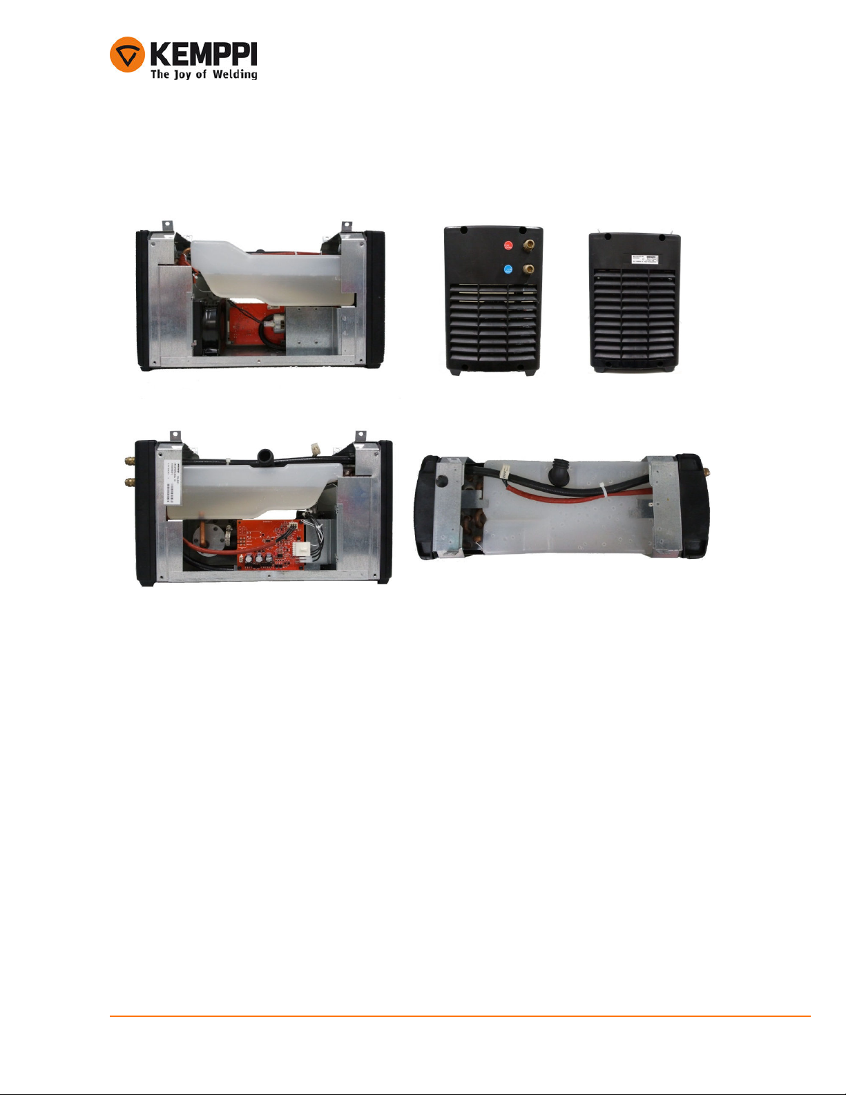
3.3. Construction .............................................................................................................................................. 4
3.3.1. Inner structure.................................................................................................................................... 5
3.3.2. A001 control card structure................................................................................................................ 6
3.4. Description of operation ............................................................................................................................ 7
3.4.1. A001 control card............................................................................................................................... 7
3.4.2. Pump-motor assembly....................................................................................................................... 7
3.4.3. Water circulation components (Radiator, water hoses, tank and pressure damper system) ............ 7
3.5. Control card jumpers................................................................................................................................. 8
3.6. Control card LEDs..................................................................................................................................... 8
4. SERVICE INSTRUCTIONS.............................................................................................................................. 9
4.1. Cooling liquid............................................................................................................................................. 9
4.2. Cooler maintenance .................................................................................................................................. 9
4.2.1. Detaching and fastening the pump .................................................................................................... 9
4.2.2. Fastening the Generation1 dual water hose to the pump ............................................................... 10
4.2.3. Pump maintenance .......................................................................................................................... 10
4.3. Measurements and tests......................................................................................................................... 11
4.3.1. Troubleshooting in error cases ........................................................................................................ 11
4.3.2. Operational tests.............................................................................................................................. 12
4.3.2.1. Under pressure alarm............................................................................................................... 12
4.3.2.2. Over pressure alarm................................................................................................................. 13
4.3.2.3. Normal operational pressure .................................................................................................... 13
4.3.2.4. Water flow test.......................................................................................................................... 13
4.3.3. Cooler voltages................................................................................................................................ 14
5. FIRST GENERATION CONTROL CARD SP002447 .................................................................................... 15
6. SECOND GENERATION CONTROL CARD SP004736 ............................................................................... 16
APPENDIX.......................................................................................................................................................... 17

Service manual Mastercool 30 Version 1.0 1.11.2011
1
Kemppi Oy
1. READ THIS FIRST
Before removing any covers or commencing any testing or measurement disconnect the power source
from the mains voltage
DC voltage may still exist after the removal of the input voltage. Machine discharges the voltage while it is
turned off, but it is always better to ensure this by measuring the voltage
Wait at least one minute for the capacitors to become discharged.
Different digital multimeters (later DMM) may give different values depending on the specifications they
have. For example diode measuring values may vary between the DMM models. In this manual Fluke
179 DMM is used.
The device may be repaired only by a person legally authorized to perform electric work.

Service manual Mastercool 30 Version 1.0 1.11.2011
2
Kemppi Oy
2. GENERAL
Mastercool 30 is membrane pump type cooler for water cooled mig guns. Membrane pump can generate
up to 10 bar pressure so it needs electronically limited control logic.
Control logic and pump motor both uses low voltage power (+24VDC) and cooler does not have any high
voltage inside. Secondary side +24VDC is generated in Mastertig MLS 3000/3003 ACDC
Mastercool 30 can have several different control cards depending the manufacturing time. First type was
SP002447 (card number W002447, versions A, B and C). This card has trimmer for adjusting the under
pressure limit and jumpers for several configuration options. In production from the beginning to 6/2009.
Second control card type was SP004736 (card number W004736, versions A and B) and had updated
motor current measuring. This card did not have any trimmers, only jumpers. In production from 7/2009 to
end of 2010.
Third card type is SPW006214 (card number W004736), it has same control logic as Mastercool 20. Main
idea compared to earlier cards is that motor has lower running speed and better ability to tolerate long
water hoses and cold temperatures. In production from the beginning of 2011.
This manual is mostly for coolers with third type card SPW006214. In the end of manual there are some
information and jumper settings for old cards. There is also instructions how to adjustment trimmer in card
SP002447. For more information please see the following old manuals found in Kemppi net:
•Servicemanual_Fast_Master_Kempact10_Master30.VX.X_EN.pdf (original manual for
Hydrocool pump coolers with first type control card)
•Servicemanual_membrane_pump_coolers.VX.X_EN.pdf (second version for Hydrocool
pump coolers with second type card)
Mastercool 30 has been made with two different types of pressure dampening systems. Originally cooler
had a dual component hose in pump output. This was replaced in 3/2010 by normal rubber output hose
with copper pressure damper.
NOTE! These two different types of pressure dampening systems
are meant to use separately not together.

Service manual Mastercool 30 Version 1.0 1.11.2011
3
Kemppi Oy
3. TECHNICAL INFORMATION
3.1. Technical data
Mastercool 30
Operating voltage 24VDC
Cooling power 1.0 kW
Connection capacity 100% ED 50W
Maximum pressure 4.0 bar
100 % ED I
eff1
12.9 A
Cooling liquid 20% - 40% glycol-water
Tank volume Approx. 3 l
External dimensions LxWxH 500x180x260mm
Weight 8 Kg
3.2. Wiring diagram

Service manual Mastercool 30 Version 1.0 1.11.2011
4
Kemppi Oy
3.3. Construction
The cooling fan is installed so that the air flows from the left side plate to Z001 card. Air comes out
through the front and the back plate grills.
Left side
Back
Front
Right side
Up

Service manual Mastercool 30 Version 1.0 1.11.2011
5
Kemppi Oy
3.3.1. Inner structure
1. Fastening points to power source
2. Hot water/return snap connector (red)
3. Cool water/output snap connector (blue)
4. Hydrocool pump
5. A001 control card
6. Water tank filling hose
7. Water tank
8. Cooling fan
9. Radiator (inside the chassis)
1.
4.
5.
3.
2.
6.
7.
9.
8.

Service manual Mastercool 30 Version 1.0 1.11.2011
6
Kemppi Oy
3.3.2. A001 control card structure
1. Connector X5, not in use
2. Connector X7, Positive output for pump motor
3. Connector X8, Negative output for pump motor
4. Connector X4, PTC and cooling fan connector
5. Connector X3, Control connector to power source
6. LED H1
7. LED H2
1.
2.
3.
4.
5.
7.
6.

Service manual Mastercool 30 Version 1.0 1.11.2011
7
Kemppi Oy
3.4. Description of operation
Mastercool 30 can be divided to three parts: A001 control card, pump with motor and water circulation
components.
Note that Mastercool has had two different principles for pressure dampening and three different types of
control cards depending the manufacturing time.
3.4.1. A001 control card
•Control card controls the pump start and stop. This is made by the start signal of power
source control card.
•It monitors the water temperature. PTC resistor is +60 degrees of Celsius.
•A001 card monitors water pressure by measuring the pump current. If pressure goes
over or under the limit card give fault-signal to power source via X3-1
•Card controls cooling fan. Its start is related to pump running and has shut down delay
•Card has several jumpers to activate alternative characteristic functions in problem
cases. Jumpers are described in next chapter.
3.4.2. Pump-motor assembly
•Pump works by membrane principle (like piston) and can develop up to 10 bar pressure.
This is limited electronically to 5 bars to avoid internal damage and to protect water
hoses. Motor runs piston that moves the membrane. Membrane develops pressure that
is hold with two pressure valves. Piston type movement has a vibration as a side effect
and it must be filtered with damper. Pump can have water flow up to 0,8l/min.
•Pressure valves keep the pressure high and water flow in right order
•Motor runs the membrane pump piston. It uses voltage +5,2VDC.
•Pump input is connected to the copper pipe from the tank and output has integrated
spindle for output water hose.
•Note that motor should be connected to A001 control card with two wires with flat
connectors X7 and X8. If old connection (A001 X4) is used with motor wires, it should be
replaced.
3.4.3. Water circulation components (Radiator, water hoses, tank and pressure damper system)
•Radiator cools the heated water while it runs through it.
•Tank holds the cooling liquid and the volume is approximately 3 liters.
•Via Output water hose the cooling liquid runs to the snap connector.
•Pressure damper system:
oDual type Water hose works as a pressure damper in old coolers
manufactured up to 4/2010. Inner hose was made of silicon to enlarge and
diminish when pressure changes. Outer hose was made of reinforced rubber
to limit the enlarging inner silicon hose. Together these makes generation 1
pressure damper system.

Service manual Mastercool 30 Version 1.0 1.11.2011
8
Kemppi Oy
oGeneration 2 pressure damper system has a normal rubber single output
water hose and it is connected to disk-like pressure damper. It is made of
copper and has a single chamber to reduce the pressure variations. This
type damping circuit is used since 4/2010.
3.5. Control card jumpers
Jumpers control several functions and their behavior can be changed if faced frequent problems.
Normally Hydrocool pump system may have two types of malfunctions: pressure is rising to abnormal
level or coolant level is too low.
In some cases high pressure is consequence of very long water cables or cold temperature. In these
cases jumpers X11 and X10 can be used to get more tolerance to keep cooler running.
While coolant level is too low the only possibility is to add more of it. Jumper X9 is only to check if the
cooler alert is because of low pressure.
See service instructions to get more information how to use jumpers to rectify problems.
X80 For test use only
*Open – Keep always open
X9 Pump motor current over and under pressure alarm.
*Open – Alarm is possible
Closed – Alarm disabled
X10 Pump motor current over pressure alarm.
*Open – Alarm is possible
Closed – Alarm disabled
X11 Pump motor current over pressure alarm level.
*Open – Alarm level is normal
Closed – Alarm level is raised
3.6. Control card LEDs
H1 = Over temperature
H2 = Over and under pressure alert. This LED goes on also if temperature alert is given

Service manual Mastercool 30 Version 1.0 1.11.2011
9
Kemppi Oy
4. SERVICE INSTRUCTIONS
4.1. Cooling liquid
With Mastercool 30 it is possible to use two kind of cooling liquids: Water mixed with ethanol or glycol.
Ethanol based coolant is recommended for better torch durability. It also keeps the pump clean and
smoothly running. Ethanol can be mixed with water up to 40% vol, higher volume gets flammable.
Lower % vol (no less that 15% vol) may be used if cooler is not running in subzero temperatures.
Cooler is tested with glycol based coolant and system can stay fully operational. The problem is that
glycol may corrode torch metal parts because of electricity (welding voltage in torch). Another thing is that
glycol builds up small particles in the long run and these might get the pump pressure valves stuck if
coolant is not changed frequently.
4.2. Cooler maintenance
Water cooler needs maintenance to keep it running in long term use. Water tank and pump should be
cleaned frequently. Time frame depends on the used coolant and coolers working hours. Ethanol keeps
system more clear than glycol. It is best to check in certain periods of time the coolant condition and
change if needed. Once water tank is getting dirty it should be flush with clean water.
Pump has pressure valves ant they may get dirty as well. If water circulation is slowing down and errors
are faced even with short water hoses, it is preferred to maintain the pump itself. See the following
chapters for more information.
4.2.1. Detaching and fastening the pump
Detaching the pump:
•Open the side panel
•Disconnect the pump motor connectors
•Detach the copper pipe
•Detach the water hose clamp
•Note! Additional support by finger is needed while losing the hose clamp screw
to avoid damaging the nib
•Detach the pump from the cooler frame
Attaching the pump back to the cooler is made in the opposite rule. Note that additional support is needed
while the water hose clamp is tightened. If used dual component water hose see the next chapter to get
reliable connection.
Hose clamp
Copper pipe

Service manual Mastercool 30 Version 1.0 1.11.2011
10
Kemppi Oy
4.2.2. Fastening the Generation1 dual water hose to the pump
It is important to make connection right way because otherwise connection may leak or even hose slip
away. While attaching the two component water hose to the pump nib, first carefully install the inner hose
to the nib and then the outer hose upon the inner hose. Only then you can be sure to get the reliable
fastening. Use your index finger to support the pump nib to avoid bending it while tightening the hose
clamp. Be sure to tight clamp enough.
4.2.3. Pump maintenance
To maintain the pump:
•Open the 6 screws in the top of the pump
•Two screws are PT and four are normal
Water hose nib
Rubber sealing ring for
the copper pipe
Long screws fastened to the bolts located
in the lower pump frame (4 pieces)
Short PT screws fastened to the upper
pump frame (two pieces)

Service manual Mastercool 30 Version 1.0 1.11.2011
11
Kemppi Oy
•Open the pump crown and check the pressure valves if they are clean and intact
•Clean the area around the valves and replace valves if needed
•Note! Be careful while installing valves, they must be in right sides, if not pressure won’t
rise at all
•Detach membrane support from piston and check the condition, replace if needed
oNote! When assembling the pump, be careful NOT to over tighten PT
screw to avoid damaging the parts
•Before attaching the crown cover be sure the rubber sealing ring is fully escorted
through the crown cover and its sealing
•While attaching the crown cover, be careful NOT to over tighten two PT screws to avoid
damaging the pump frame
4.3. Measurements and tests
4.3.1. Troubleshooting in error cases
The next two chapters may give ideas how to rectify possible cooler error cases. Before making further
actions to cooler it is best to change another TIG torch to be sure it is not the source of problems. Check
also that coolant level is high enough and add if needed. See the LED information in the A001 control
card.
Over pressure:
In some cases high pressure is consequence of very long water cables or cold temperature. In these
cases jumpers X11 and X10 can be used to get more tolerance to keep cooler running.
•Close X11 to get more tolerance for over pressure alarm
Pressure valve from membrane chamber
to pressure chamber and to water hose
(valve on this side)
Pressure valve from incoming chamber to
the membrane chamber (valve on the
other side)
Rubber sealing
ring
Crown cover
and its sealing
Piston
Membrane chamber
in the crown
Membrane
Membrane support
and PT screw

Service manual Mastercool 30 Version 1.0 1.11.2011
12
Kemppi Oy
•If problems continue close X10 to disable over pressure alarm
If these do not help, the problem is not the over pressure, see the next section (Under pressure or no
water circulation).
Under pressure or no water circulation:
If coolant level is fine and jumpers X11 and X10 do not solve the cooler error, jumper X9 can be used to
check if the cooler alert given is because of the air bubble in the pump or leakage of pressure valves or
membrane. Before closing the X9 check that jumpers X11 and X10 are closed.
Note! Jumper X9 should be kept open and closed only for test purposes, because lack of the disturbed
water circulation alert may affect the TIG torch to burn.
Checking the water circulation:
•Disconnect the blue snap connector and use screwdriver to unlock it (by pressing inside
the connector).
•Try to run some water to container; if water flows circulation is ok.
•Check that pump can raise the pressure while water hoses are connected (See the next
section “Normal operational pressure”).
4.3.2. Operational tests
During the maintenance it is always good idea to check some basic operations of the cooler. To be sure
control electronics and pump itself works as designed, there is basically four tests to execute. Pressure
meter is a nice tool to make reliable operational tests (suppressed meter is better because of the variable
pressure). Best place for pressure meter is just after the output snap connector behind the cooler (blue
mark).
Note! Remember to close the water circulation with hose loop or TIG torch, otherwise the pressure will
rise to the maximum and snap connector might start to leak.
4.3.2.1. Under pressure alarm
When water tank is empty or pressure is under 1 bar, control electronics activate the alarm
•It can be seen by led H2 illuminating
•If under pressure lasts over 7 seconds, cooler gives error message (X3-1 goes to 0)
Pressure meter connection to the
output snap connector, marked as blue

Service manual Mastercool 30 Version 1.0 1.11.2011
13
Kemppi Oy
4.3.2.2. Over pressure alarm
When water circulation is blocked or resistance is too high, control electronics activate alarm
•If pressure is over approx. 5 bars led H2 illuminates
•This can be simulated by bending output water hose just after the snap connector
•If over pressure lasts several seconds cooler gives error message (X3-1 goes to 0)
4.3.2.3. Normal operational pressure
Working pressure for this cooler is depending on the length of the cables and environment temperature.
Normally pressure is between 1,5 and 5 bars.
•E.g. while using 16 meter long torch and/or working in temperatures under 0 pressure
can be up to 4 bars.
•If normal working pressure is near 1 bar, there can be problem in pump membrane
and/or pressure valves. See next pages to maintain the pump.
•Water cooled gun adds approx. 0,5 bars and this should be noticed when making
simulated pressure measurements. If using water hose loop in the end of the feeder
connection instead of a gun, working pressure will be lower than in real welding
situation.
4.3.2.4. Water flow test
•Get a container with a scale for the water volume
•Run water from cooler to the container and use stop watch to have exact time = t
•See the result in the container scale = V1
•Use formula below to calculate water flow per minute
Example 1:
Acceptable water flow per minute is more than 5dl/min. If water flow is less, this can be a mark of
problems in the pump.
t
VV
total
60
1
⋅=
dldl
s
s
dl
t
VV
st
dlV
total
824
30
60
4
60
30
4
1
1
=⋅=⋅=⋅=
=
=

Service manual Mastercool 30 Version 1.0 1.11.2011
14
Kemppi Oy
4.3.3. Cooler voltages
Voltage measuring gives basic information of possible problems. Mastercool 30 requires +24 VDC for
control electronics, pump motor and cooling fan.
Input voltage from the power source:
•+24VDC X3-3
•Ground X1-3
Pump motor voltage:
•+5-6VDC X7
•Ground X8
Cooling fan:
•+24VDC X4-12
•Ground X4-11
X3
X4
X8
X7

Service manual Mastercool 30 Version 1.0 1.11.2011
15
Kemppi Oy
5. FIRST GENERATION CONTROL CARD SP002447
X9 Change machine pressure-/flow characteristic curve.
Open - the pressure is lower
closed – higher pressure
X20 Cooling unit start
*Open – waiting for start signal
Closed – Continuous run
X21 Liquid temperature alarm.
*Open – PTC monitoring by cooler
Closed – PTC monitoring by power source
X22 Pump motor current minimum limit alarm, pressure low or no water.
*Open – alarm on
Closer – alarm off.
H1 Cooling liquid temperature too high.
H2 Pump motor current too low, no water. Alarm level can be adjusted
by trimmer R57 (Default 230mV – 1,4A)
H3
Pump motor current too high. Blocked water hoses, no
circulation.
Adjusting pump motor current minimum: measuring points X7 and X8, adjust voltage using R57 to 230mV
(current limit will be then 1,4A). When adjusting the current limit pump should not be running.
Operational voltages and used connectors are the same as in the card SPW006214.
X3
X4
R57 X21X22X20 X9
H1
H2
H3
X7/X8

Service manual Mastercool 30 Version 1.0 1.11.2011
16
Kemppi Oy
6. SECOND GENERATION CONTROL CARD SP004736
X20 Cooling unit start.
*Open – Waiting for power source start signal
Closed – Continuous run
X21 Liquid temperature alarm.
*Open – PTC monitoring by cooler
Closed – PTC monitoring by power source
X22 Pump motor current minimum alarm, pressure low or no water.
*Open – alarm on
Closed – alarm off
H1 Cooling liquid temperature too high.
H2 Pump motor current too low. Cooling liquid level too low, no liquid or air
bubble in the pump.
H3
Pump motor current too high. Blocked water hoses, no circulation.
Operational voltages and used connectors are the same as in the card SPW006214.
H2
H3
H1
X22 and X20
X21

Service manual Mastercool 30 Version 1.0 1.11.2011
17
Kemppi Oy
Notes

Table of contents
Other Kemppi Freezer manuals