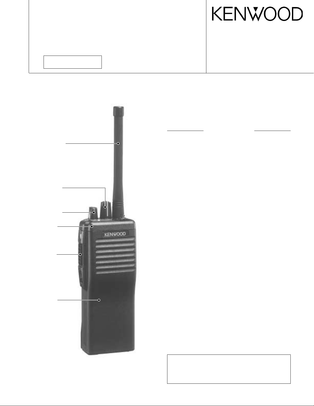
Kenwood TK-290 User manual

Document Copyrights
Copyright 2006 by Kenwood Corporation. All rights reserved.
No part of this manual may be reproduced, translated, distributed, or transmitted in any
form or by any means, electronic, mechanical, photocopying, recording, or otherwise, for
any purpose without the prior written permission of Kenwood.
Disclaimer
While every precaution has been taken in the preparation of this manual, Kenwood
assumes no responsibility for errors or omissions. Neither is any liability assumed for
damages resulting from the use of the information contained herein. Kenwood reserves
the right to make changes to any products herein at any time for improvement purposes.

© 2001-3 PRINTED IN JAPAN
B51-8423-10 (N)1023
VHF FM TRANSCEIVER
TK-290
SERVICE MANUAL
Photo is TK-290 K type.
Does not come with antenna.
Antenna is available as an option.
CONTENTS
GENERAL ................................................................. 2
SYSTEM SET-UP ..................................................... 2
OPERATING FEATURES ......................................... 3
REALIGNMENT...................................................... 11
CIRCUIT DESCRIPTION......................................... 17
SEMICONDUCTOR DATA..................................... 25
DESCRIPTION OF COMPONENTS ....................... 26
PARTS LIST ............................................................ 28
EXPLODED VIEW .................................................. 36
PACKING ................................................................ 37
DISASSEMBLY FOR REPAIR ................................ 38
ADJUSTMENT ....................................................... 39
PC BOARD VIEWS
FINAL UNIT (X45-3592-71) ............................... 50
CONTROL UNIT (X53-3930-XX)....................... 51
TX-RX UNIT (X57-5390-10) .............................. 55
SCHEMATIC DIAGRAM ........................................ 61
BLOCK DIAGRAM.................................................. 67
LEVEL DIAGRAM ................................................... 69
TERMINAL FUNCTION .......................................... 70
KNB-17A (Ni-Cd BATTERY) ................................... 71
KMC-25/26 (SPEAKER MICROPHONE) ................ 72
KSC-19 (CHARGER) ................................................ 73
KSC-20 (RAPID CHARGER) .................................... 73
KPG-36 (PROGRAMMING INTERFACE CABLE)
...... 73
KRA-14 (HELICAL ANTENNA) ............................... 73
SPECIFICATIONS............................... BACK COVER
CAUTION
When using an external power connector,
please use with maximum final module protec-
tion of 10V
REVISED
Antenna
(KRA-14 : Option)
Cabinet assy
(A02-2139-63)
Knob assy (SEL)
(K29-5282-04)
Knob assy (VOL)
(K29-5283-04)
Panel assy
(A62-0537-53)
Knob assy
(Side key)
(K29-5441-04)

2
TK-290 GENERAL / SYSTEM SET-UP
INTRODUCTION
SCOPE OF THIS MANUAL
This manual is intended for use by experienced techni-
cians familiar with similar types of commercial grade com-
munications equipment. It contains all required service in-
formation for the equipment and is current as of the publica-
tion data. Changes which may occur after publication are
covered by either Service Bulletins or Manual Revisions.
These are issued as required.
ORDERING REPLACEMENT PARTS
When ordering replacement parts or equipment informa-
tion, the full part identification number should be included.
This applies to all parts : components, kits, or chassis. If the
part number is not known, include the chassis or kit number
of which it is a part, and a sufficient description of the re-
quired component for proper identification.
PERSONNEL SAFETY
The following precautions are recommended for person-
nel safety :
• DO NOT transmit until all RF connectors are verified se-
cure and any open connectors are properly terminated.
• SHUT OFF and DO NOT operate this equipment near
electrical blasting caps or in an explosive atmosphere.
• This equipment should be serviced by a qualified techni-
cian only.
SERVICE
This radio is designed for easy servicing. Refer to the
schematic diagrams, printed circuit board views, and align-
ment procedures contained within.
NOTE
WE CANNOT guarantee oscillator stability when using
channel element manufactured by other than KENWOOD or
its authorized agents.
FCC COMPLIANCE AND TYPE NUMBERS
Model
Type acceptance number
Frequency range
Compliance
TK-290 ALH21893110 136~174MHz Parts 22,74,80,90
Unit X57-539X-XX X53-393X-XX X45-359X-XX DTMF
Model & Frequency range Remarks keypad
destination 0-10 0-11 0-12 2-71
TK-290 K ✓✓ ✓136~174MHz 1st IF : 44.85MHz –
K2 ✓✓✓136~174MHz LOC : 45.305MHz ✓
Merchandise received
License and frequency allocated by FCC
Choose the type of transceiver
Transceiver programming
Are you using the optional antenna?
Delivery
Are you using the speaker microphone?
TX/RX 136~174 5W TK-290 K,K2
Frequency range (MHz) RF power Type
A personal computer (IBM PC or compatible), programming
interface (KPG-36), and programming software (KPG-38D)
are required for programming.
(The frequency, and signalling data are programmed for the
transceiver.)
YES
YES YES
NO
NO NO
KRA-14
Helical antenna
(Option)
With
antenna?
KMC-25
KMC-26
SYSTEM SET-UP

3
TK-290
OPERATING FEATURES
1. Getting Acquainted
1-1. Key Descriptions
TX/Busy/Battery low indicator
Lights red while transmitting. Lights green while receiv-
ing. Flashes red when the battery power is low while
transmitting; replace or recharge the battery.
Note : This indicator can be disabled by your dealer.
Power switch/Volume control
Turn clockwise to switch ON the transceiver. Turn coun-
terclockwise, until a click sounds, to switch OFF the
transceiver. Rotate to adjust the volume level.
Selector
Rotate this control to activate its programmable function
(Page 8).
Toggle switch
Switch the toggle position to activate its programmable
function (Page 8).
Top 1
Top 2
Orange
Side 1
Side 2
PTT (Push-To-Talk) switch
Press this switch, then speak into the microphone to call
a station.
Press these PF (programmable function)
keys to activate their programmable func-
tions (Page 8)
DTMF keypad (keypad models only)
Press the keys on the telephone keypad to send DTMF
tones.
Universal connector
Connect the external speaker/microphone (optional)
here. Otherwise, keep the supplied cover in place.
1-2. Display
Alphanumeric display
Displays the operating group or channel number, or the
group or channel name. When making a DTMF or 2 Tone
call, the display will alternate between CALL and the
channel. Also displays various menu functions.
7 Segment display
Displays the operating group or channel number. Also
displays tA (Talk Around), P1 (Priority1), P2 (Priority2), PP
(Priority1 and Priority2), or HC (Home Channel); depend-
ing on the function being used.
A (Add) indicator
Appears when a channel is added to the scanning se-
quence.
SCN (Scan) indicator
Appears when Scan mode is active.
MON (Monitor) indicator
Appears when the monitor function is active.
LO (Low) indicator
Appears when low power is selected.
OPT indicator
Appears when Operator Selectable Tone is enabled.
AUX (Auxiliary) indicator
Appears when Aux is ON. Appears and blinks when the
optional scrambler board is enabled.
Note : The alphanumeric and 7 segment displays can be
inverted if a PF key or the toggle switch is programmed
with Invert Display (Page 8).
ABAB
SMA male type
antenna connector Battery pack
release latch
Microphone
Display
Speaker

4
TK-290
2. Scan Operating
2-1. Scan Types
•Single Group Scan
You can scan all valid (ADD) channels in the displayed
group that can be selected with the group selector.
•Multiple Group Scan
You can scan all valid (ADD) channels in the all valid
(ADD) group.
2-2. Scan Start Condition
One or more non-priority channels must be added to all
channels that can be scanned. The transceiver must be in
normal receive mode (PTT off).
When you activate the key or the toggle switch (to right
position) programmed to the scan function, the scan starts.
The scan icon “SCN” lights and “SCAN” or revert channel
(programmable) is indicated on 7-digit alphanumeric display.
2-3. Scan Stop Condition
The scan stops temporarily if the following conditions are
satisfied.
1) A carrier is detected, then signalling matches on chan-
nels for which receive the signalling is set by the pro-
gramming software.
2) A carrier is detected on the channel for which receiving
signalling is not set by the programming software or
when the monitor (signalling cancel) function is activated.
2-4. Scan Channel Types
1) Priority channel 1 is the most important channel for the
scan, and always detects a signal during scan and when
the scan stops temporarily.
2) Priority channel 2 is the next important channel for the
scan, and always detects a signal during scan and when
the scan stops temporarily at a channel other than priority
channel 1.
3) Non-priority channels detects a signal during scan. For
the channels that can be selected with the group or chan-
nel selector when the scan does not occur, adds an indi-
cator “A” lights.
2-5. Priority Channel Setting
Priority channels 1 or 2 can be set as follows with the
programming software (KPG-38D).
1) Specify priority channels 1 or 2 as fixed priority channels.
2) Make selected channels, priority channels.
3) Operator delectable
Specify the initial channel before the operator changes it.
2-6. Scan Type According to the Priority Channel
1) When no priority channels are set : Only the non-priority
channels are scanned.
If a non-priority channel stops temporarily, it stops until
there is no signal on the channel.
OPERATING FEATURES
2) When one priority channel is set : Either priority channel
1 or 2 is scanned.
If a non-priority channel stops temporarily, a priority chan-
nel signal is detected at certain intervals.
If a priority channel stops temporarily, it stops until there
is no signal on the priority channel.
3) When two priority channels are set : The non-priority
channel, priority channels 1 and 2 are scanned.
If a non-priority channel stops temporarily, priority chan-
nel 1 and 2 signals are detected at certain intervals.
If priority channel 2 stops temporarily, the priority chan-
nel 1 signal is detected at certain intervals.
If priority channel 1 stops temporarily, it stops until there
is no signal on priority channel 1.
2-7. Revert Channel
The revert channel is used to transmit during scanning
and set by the programming software (KPG-38D).
1) Priority 1
The transceiver reverts to the priority channel 1.
2) Priority 1 with talkback
The transceiver reverts to the priority channel 1.
If you press PTT during a resume timer (dropout delay
time, TX dwell time) or calling, you can transmit on cur-
rent channel to answer to the call however revert channel
is set to priority channel 1.
After resume time, scan re-starts and transmission chan-
nel is return to priority channel 1.
3) Priority 2
The transceiver reverts to the priority channel 2.
4) Priority 2 with talkback
The transceiver reverts to the priority channel 2.
If you press PTT during resume timer (dropout delay
time, TX dwell time) or calling, you can transmit on cur-
rent channel to answer to the call however revert channel
is set to priority channel 2.
After resume time, scan re-starts and transmission chan-
nel is return to priority channel 2.
5) Selected channel
The transceiver reverts to the channel before scanning or
the channel that you changed during scan.
6) Last called channel
The transceiver reverts to the last called channel during
the scan.
7) Last used channel
The transceiver reverts to the last used (transmitted)
channel during scan. “Last used” revert channel in-
cludes talkback function.
8) Selected with talkback
The transceiver reverts to the channel before scanning or
the channel that you changed during scan.
2-8. Scan End
When you reactivate the key or the toggle switch (to left
position) programmed to the scan function during scan
mode, the scan ends.
The scan icon “SCN” and “SCAN” or revert channel (pro-
grammable) display goes off.

5
TK-290
2-9. Temporarily Delete/Add
It is possible to delete or add channel temporarily during
scan. When scan stops on unnecessary channel for ex-
ample by interference of the other party, activate the delete/
add function (for example press the key), then that channel
is deleted temporarily and scan re-start immediately.
When you would like to add the deleted channel tempo-
rarily to scan sequence, select the desired (deleted) channel
during scan, activate the delete/add function (for example
press the key) before scan re-start.
That channel is added temporarily to scan sequence. The
temporary deleted or added channels are returns to pre-set
delete/add, when the transceiver exits from scan mode.
3. Optional Features
You can use these features using the programming soft-
ware (KPG-38D).
3-1. Alphanumeric Display (Group/Channel Name)
The programming software (KPG-38D) enables you to set
the alphanumeric display for group/channel name. The total
text size of group and channel name are 7-digits.
For example, If you set 2-digits for group name, then you
can use 5-digits for channel name. The characters can be
used as shown in Figure 1.
3-2. Beep Tones
The beep tones (power on tone, control tone, warning
tone, alert tone) are individually programmable to the fixed
level 0 to 31 or follow the mechanical volume position.
3-3. Minimum Volume
The minimum volume is programmable (0 to 31). The
transceiver remains the minimum volume level however the
mechanical volume position is set to zero.
ABCDE FGH I
JKLMNOPQR
STUVWXYZ
123456789
0-
All on
Fig. 1
3-4. Squelch Threshold Level
Squelch threshold level value.
0 (Most loose)~15 (Most tight)
3-5. BCL (Busy Channel Lockout) Override
You can transmit in spite of Busy Channel Lockout situa-
tion. For example : To make an emergency voice call.
To transmit under busy channel lockout situation, press
PTT once more within approx. 500ms after the PTT release.
3-6. Selective Call Alert LED
You can select whether or not the LED on the transceiver
flashes in an orange color when Selective call was occurred.
3-7. Battery Warning
This transceiver has battery warning feature. If the low
voltage is detected during transmission, the transceiver
warns it by flashing red “LED”.
Then more low voltage is detected during transmission,
the transceiver stops transmission and warns it by flashing
red “LED” and beep.
Please notice “standard” for the battery exchange,
charging time by flashing red LED and beep.
3-8. Busy LED
You can program the enable or disable the busy “LED”
function when a carrier is detected. “Disable” saves battery
life.
3-9. TX LED
You can program the enable or disable the transmission
“LED” function.
3-10. 2-Digit 7-Segment Display
You can use 2-digit 7-segment the display to display the
channel number or group number. It is useful when the
main (7-digit 13-segment) display indicates group or channel
name.
3-11. Invert Display
Main (7-digit 13-segment) display and sub (2-digit 7-seg-
ment) display can be programmed to invert display.
It is easy to read the display when the operator sus-
pended the transceiver on a waste belt. The operator also
can change the display between normal and invert using
key. Refer the invert display function of key function.
3-12. Clear to Transpond
The transceiver waits the transpond of 2-Tone/DTMF if
channel is busy until channel open. This feature prevents
the interference to other party.
3-13. External Speaker
It can be selected if the receive sound is made by SP-Mic
SP or the main body SP at a SP-Mic mount.
3-14. Noise Cancelling MIC
Enable or disable the noise cancelling function of the in-
ternal microphone. It is not valid for the external SP/MIC.
OPERATING FEATURES

6
TK-290
3-15. Mode (Enable/Disable)
The transceiver has many special modes mainly for main-
tenance.
· Self Programming mode
· Panel Test mode
· Clone mode
· Firmware Programming mode
· Version info.
It is possible to set enable/disable for each mode. We
recommend to set these mode to Disable after set up to
save contents.
3-16. ID
The transceiver is capable to have ID. The format is
DTMF, MSK or ANI board (if installed). The timing that the
transceiver sends ID is programmable.
Connect ID : Connect ID is send on beginning of trans-
mission.
Disconnect ID : Disconnect ID is send on end of trans-
mission.
Both : Connect ID is send on beginning of transmission
and disconnect ID is send on end of transmission.
Off : Sending ID function is disabled.
There is also “PTT ID” setting for each channel. Refer
“PTT ID” of channel feature.
When you use an ID code for ANI board, the ID code and
transmitting timing are configured to the optional ANI board.
3-17. OST (Operator Selectable Tone)
The transceiver is capable to have “OST” function and
16 tone pair (QT/DQT) with max 7-digit name for each tone
pair.
•“OST”Back Up
The transceiver is programmable the selected “OST”
code is memorized or not. If you set to Disable (no memo-
rized), the “OST” function always starts at “off”.
•Direct “OST”
It is possible to call “OST” number directory using key-
pad. In this case, keypad is used for “OST”, then “DTMF
Auto PTT”, “DTMF Auto Dial” functions by keypad are not
usable.
3-18. Emergency
•Active Time
Automatic transmission period in the emergency mode.
•Interval Time
Interval time between the automatic transmissions.
•Duration of Locator Tone 1
Duration of an alert tone before the automatic transmis-
sion is performed.
•Duration of Locator Tone 2
Duration of an alert tone after the automatic transmission
is performed.
•Man Down Delay Time
Delay time of entering the emergency mode when the
internal Man Down port becomes active.
•Man Down Pre-alert
Wait time of the alert tone when the internal Man Down
port becomes active to enter the emergency mode. (After
an alarm sounds, the transceiver waits for the programmed
wait time then enter the emergency mode.)
•Emergency Channel Display
Setting for the display in the emergency mode.
The transceiver can be programmed to display “EMER-
GENCY” channel name when it is in emergency mode.
If you set to “off” by KPG-38D the transceiver shows se-
lected group/channel/status before entering to the emer-
gency mode however the transceiver is in an emergency
mode.
•Emergency Mode Type
Speaker mute on or off in the emergency mode.
•Emergency Type
Select an Emergency code format from DTMF, MSK, ANI
board or OFF (Disabled).
•Emergency DTMF ID
The Fleet number when you select DTMF in the emer-
gency type.
•Emergency Call Fleet
The emergency fleet number when you select MSK in
the emergency type.
•Emergency Call ID
The emergency DTMF ID code when you select MSK in
the above emergency type.
3-19. Radio Password (Keypad Model Only)
The radio password prevent unauthorized users opera-
tion. Every time the power on, transceiver is locked and
unusable until entering correct password.
Enter pre-programmed password by FPU and [#] key
causes the transceiver unlocked.
3-20. Data Password
The data password prevents unauthorized reading of the
programmed transceiver data by FPU. Enter pre-pro-
grammed password in FPU reading process. This password
also protects the clone.
Enter pre-programmed password by FPU and [#] key to
clone.
OPERATING FEATURES

7
TK-290
4. Group Features
You can use these features using the programming soft-
ware (KPG-38D).
4-1. “TOT”(Time-Out Timer)
The transceiver has the “TOT”. This parameter selects
the period of time users can continuously transmit.
When the selected period passes, the transceiver gener-
ates an warning tone and stops the transmission.
4-2. “TOT”Pre-Alert
The transceiver has “TOT” pre-alert timer. This param-
eter selects the time at which the transceiver generates
“TOT” pre-alert tone before “TOT” is expired.
“TOT” will be expired when the selected time passes
from a TOT pre-alert tone.
4-3. “TOT”Re-Key Time
The transceiver has “TOT” re-key timer. This timer is the
time you can not transmit after “TOT” exceeded. After
“TOT” re-key time expired you can transmit again.
4-4. “TOT”Reset Time
The transceiver has “TOT” reset timer. This timer is the
minimum wait time allowed during a transmission that will
reset the “TOT” count.
“TOT” reset time causes the “TOT” to continue even
after PTT is released unless the “TOT” reset timer has ex-
pired.
4-5. Group Delete/Add
The transceiver can set the delete/add in each group. If
“Delete” is selected, the transceiver does not scan the de-
leted group in multi group scan.
4-6. Battery Save
This is the automatic battery saver during a standby
mode operation. The receiver circuit is repeated on and off
to conserve the battery life.
4-7. Signalling
Signalling “AND/OR” sets the audio unmute condition
for any channel programmed with the option signalling (2-
Tone/DTMF).
AND : “AND” requires both the valid option signalling
and the programmed QT/DQT to be received for audio to
unmute (and initiate an option signalling decode alert).
OR : “OR” requires either the valid option signalling or
the programmed QT/DQT to be received for audio to
unmute (an option signalling decode alert is only initiated
if the proper option signalling is decoded).
OPERATING FEATURES
5. Channel Features
You can use these features using the programming soft-
ware (KPG-38D).
5-1. Option Signalling
The transceiver is programmable to the option signalling
(2-Tone decode program 1, 2-Tone decode program 2, 2-
Tone decode program 3, DTMF decode) to each channel. It
is useful to receive an individual call.
Receive format is selectable “AND” or “OR” with QT/
DQT for each group. The radio response of option signalling
is programmable “(Call) Alert tone” or “Transpond” for each
option signalling (2-Tone decode program 1, 2-Tone decode
program 2, 2-Tone decode program 3, DTMF).
5-2. PTT ID
PTT ID provides a DTMF ANI, MSK ANI or ANI board ID (if
installed) to be sent with every time PTT (connect ID at be-
ginning of transmission, disconnect ID at end of transmis-
sion, or both).
You can program PTT ID “on” or “off” for each channel.
The contents of ID are programmed for each transceiver.
5-3. Busy Channel Lockout
Transmission is inhibited when the channel is busy. It is
able to set this feature “Yes” or “No” for each channel.
5-4. Beat Shift
This is the feature that the microprocessor shifts its sys-
tem clock frequency slightly to prevent the receive interfer-
ence. This transceiver can program this feature “Yes” or
“No” for each channel.
5-5. TX Power
You can set the transmission power “High” or “Low” for
each channel. The each power setting is tuned at factory.
However, you can re-tune the power, using PC Tuning
Mode of KPG-38D.
5-6. Wide/Narrow
You can set the occupied band width mode “Wide” or
“Narrow” for each channel. It is useful for the operator to
use the transceiver on various sites.
5-7. Scan Delete/Add
Scanning “delete/add” is programmable for each chan-
nel. Set the currently selected channel required to include in
the scan sequence to “add”.
The operator can change the “delete/add” information
using the key programmed to “delete/add” function.
5-8. Compander
This function reduces the noise on the communications
channel used by the transceiver and improves reception.
If Wide/Narrow function is set to wide, this function
doesn't perform.

8
TK-290
6. Key Functions
You can use these features, using the programming soft-
ware (KPG-38D). Selector function is selectable channel se-
lect or group select.
The functions for Toggle switch are listed page 8 (Fig. 2).
Right position is active for programmed function on toggle
switch except “group select”.
The functions for the top key are listed page 8 (Fig.2).
Hold action and shift action are programmable.
The functions for side key are listed page 8 (Fig.2). Hold
action and shift action are programmable.
The functions for microphone key are listed page 8
(Fig.2). Hold action is programmable.
6-1. No Function
Sounds error operation beep, and no action will occur.
Use this function when the transceiver is required to be
more simple operated.
6-2. AUX.
This function can be programmed when the voice scram-
bler board is not installed.
If this key is pressed, “AUX” icon lights on the LCD and
AUX port which is inside of the transceiver turns to the high
level. If pressed again, the “AUX” icon goes off and the
AUX ports turns to the lower level.
6-3. Channel Down
If this key is pressed once, the channel number de-
creases by one step. If this key holds down for 500ms (ap-
proximate), the channel number decreases continuously.
This key works as the squelch level adjuster in a squelch
level adjust mode. This key works as the OST (operator se-
lectable tone) number selector in the OST mode. This key
works as the SCR (voice scrambler) code selector in the
voice scrambler code select mode.
6-4. Channel Up
If this key is pressed once, the channel number increases
by one step. If this key holds down for 500ms (approxi-
mate), channel number increases continuously.
This key works as the squelch level adjuster in squelch
level adjust mode. This key works as the OST (operator se-
lectable tone) number selector in the OST mode. This key
works as the SCR (voice scrambler) code selector in the
voice scrambler code select mode.
6-5. Channel Name
This key switches the LCD display between the group/
channel number and the group/channel name.
6-6. Delete/Add
This key switches the currently displayed channel be-
tween “Delete” and “Add”.
The “Add” channel contained in the scan sequence, and
“Delete” channel is not contained. In the scan mode, this
key switches the channel delete or add temporarily.
OPERATING FEATURES
Toggle PF Keys Speaker/
Function Name Selector Switch
Microphone
PF Keys
Aux 1✓✓✓
Channel Down ✓✓
Channel Name ✓✓
Channel Select ✓
Channel Up ✓✓
Delete/Add ✓✓
Emergency Call 2✓✓
Group Down ✓✓
Group Scan ✓
Group Select ✓✓
Group Up ✓✓
Home Channel ✓✓
Invert Display ✓✓✓
Key Lock ✓✓✓
Lamp ✓✓
Low Power ✓✓✓
Monitor ✓✓✓
Monitor Momentary ✓✓
No Function ✓✓✓
Operator Selectable ✓✓
Tone
Operator Selectable ✓
Priority 1
Operator Selectable ✓
Priority 2
Scan ✓✓✓
Scrambler 3✓✓✓
Shift ✓✓
SP Attenuation ✓
Squelch Level ✓✓
Squelch OFF ✓✓✓
Squelch Momentary ✓✓
Talk Around ✓✓✓
1 This function can be selected when the scrambler board has not
been installed.
2 This function can be selected when the ANI board has been in-
stalled.
3 This function can be selected when the scrambler board has
been installed.
Note : If “Shift” is pregrammed onto one of the PF keys or the
toggle switch, the remaining PF keys can be programmed with two
different functions. If “Shift” is programmed onto a PF key and the
toggle switch, an error will occur and the function will not operate.
Fig. 2 Programmable functions

9
TK-290
6-7. Group Down
If this key is pressed once, the group number decreases
by one step. If this key holds down for 500ms (approxi-
mate), the group number decreases continuously.
This key works as the squelch level adjuster in squelch
level adjust mode. This key works as the OST (operator se-
lectable tone) number selector in the OST mode. This key
works as the SCR (voice scrambler) code selector in the
voice scrambler code select mode.
6-8. Group Up
If this key is pressed once, the group number increases
by one step. If this key holds down for 500ms (approxi-
mate), the group number increases continuously.
This key works as the squelch level adjuster in the
squelch level adjust mode. This key works as the OST (op-
erator selectable tone) number selector in the OST mode.
This key works as the SCR (voice scrambler) code selector
in the voice scrambler code select mode.
6-9. Home Channel
Press this key once, the channel switches to the pre-pro-
grammed home channel. Press this key again, the channel
goes back to the previous channel.
6-10. Invert Display
Press this key once, the displayed the group/channel
number or group/channel name are inverted. Press this key
again, the display returns to the normal.
For the operator who does not change the display and
needs “Invert” only, refer “Invert Display” setting of op-
tional feature.
6-11. Key Lock
Pressing this key causes the transceiver to accept an en-
try of only the [Shift], [KeyLock], [PTT], [Emergency],
[LAMP], [Monitor], [Monitor Momentary], [Squelch Off],
[Squelch Momentary], [SP MIC Attenuation] keys, [Selector
switch], [Volume], [Toggle], [Lamp], [Moni], [Moni momen-
tary], [SQ off] and [SQ momentary].
“Lock” is used to prevent users from unexceptable key
press which might cause a transceiver malfunction. The dis-
play does not change while the key is being locked.
Switching the transceiver off and on or pressing Key Lock
again cancels the key lock. Key locked transceiver can still
receive. Pressing this key while scanning, keys are locked
but a scanning continues.
6-12. Lamp
Press this key, the transceiver illuminates the display and
keypad back lit approximate 5 seconds. Press this key
again, the transceiver stops the illuminating.
Pressing any key except the LAMP key while the illumi-
nated restarts the 5 second timer.
6-13. Low Power
Press this key, the transmission power of all channel
changes to Low. Press this key again, the transmission
power returns to programmed value.
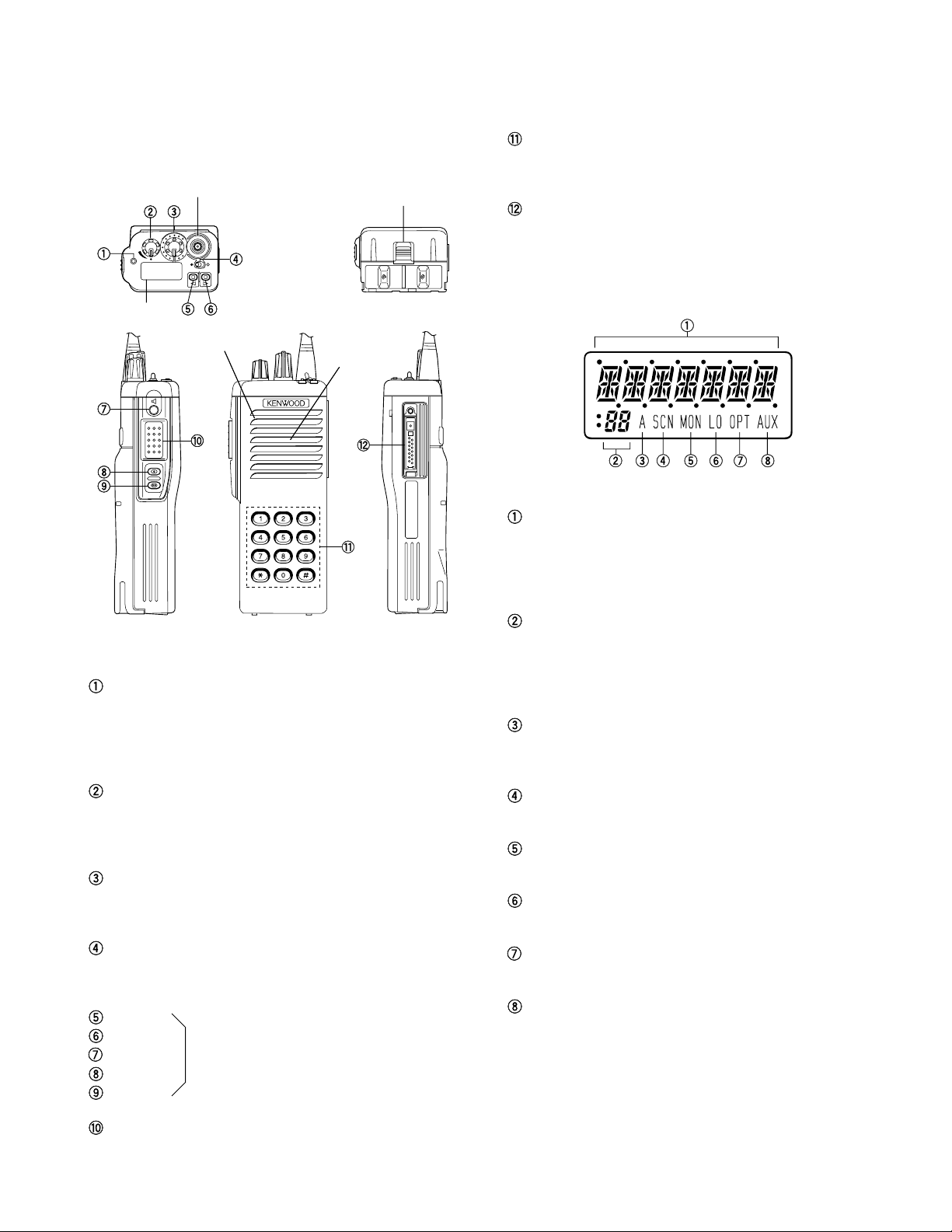
6-14. Monitor
Monitor the channel before a transmission.
Press this key once, “MON” appears and unmutes
speaker if a carrier is present, regardless of the specified
signalling (including option signalling). Press this key again,
“MON” disappears and mutes speaker.
Press this key after the Option Signalling is matched, the
Option Signaling is reset and monitor is activated. DBD
(Dead Beat Disable) mode is not reset by this operation.
6-15. Monitor Momentary
While pressing this key, the monitor function (refer 6-14)
is activated. Release this key, the monitor function is de-
activated.
6-16. Operator Selectable Tone
This key switches the pre-set decode QT/DQT and en-
code QT/DQT to OST (Operator Selectable Tone) tone pair.
Press this key, the transceiver enters to OST select
mode. In this mode, the display shows “OFF” and the op-
erator can select one of the OST tone pair using the channel
up/down key or the group up/down key. The display shows
“TONE ✽ ✽” and tone pair No. ✽ ✽ is selected.
Press OST key again, the transceiver exits from the OST
select mode, and returns to the group/channel mode with
“OPT” icon. “OPT” icon means that the OST tone pair is
selected. OST tone pair number or OFF can be memorized
for each channel.
16 kinds of tone pair for OST can be programmed by
KPG-38D. OST is useful to access the repeater with same
radio frequency and different tone (QT/DQT).
6-17. Operator Selectable P1
If priority channel 1 is set as “Fixed” and “None” in the
scan information. The operator can select the priority chan-
nel 1, using this key (operator selectable fixed P1).
Press this key on normal channel, the channel becomes
to priority channel 1. Previous priority channel 1 returns to
the normal channel. Press this key on the priority channel 1,
the priority 1 will be lost (no priority 1).
6-18. Operator Selectable P2
If priority channel 2 is set as “Fixed” and “None” in the
scan information. The operator can select the priority chan-
nel 2, using this key (operator selectable fixed P2).
Press this key on the normal channel, the channel be-
comes to the priority channel 2. Previous priority channel 2
returns to the normal channel. Press this key on priority
channel 2, the priority 2 will be lost (no priority 2).
6-19. Scan
Press this key starts scanning. Pressing this key stops
scanning.
6-20. Shift
This key activates “Shift + [Key]” function. It is useful
when the numbers or more of the functions are necessary.
OPERATING FEATURES

10
TK-290
6-21. Squelch Level
The preset squelch level is varied in user mode (0 to 15).
Press the key programmed to “squelch level”, the trans-
ceiver enters to “squelch level adjust mode”.
The squelch level can be adjusted by group “up/down”
function key or channel “up/down” function key. Press the
key programmed to “squelch level” again, the adjusted
level is memorized and returns to the normal user mode.
6-22. Squelch Momentary
While pressing this key, the transceiver unmutes
speaker regardless of an existence of a carrier and “MON”
appears and busy “LED” lights on.
Release this key, the transceiver mutes the speaker and
“MON” disappears and busy “LED” lights off.
6-23. Squelch Off
Press this key, the transceiver unmutes speaker regard-
less of the existence of a carrier and “MON” appears and
busy “LED” lights.
Press this key again, the transceiver mutes the speaker
and “MON” disappears and busy “LED” lights off.
6-24. Talk Around
Press this key, the transceiver uses the receive fre-
quency and the tone for transmission.
The operator can call the other party directory (without
repeater). Press this key again, the talk around function
goes off.
6-25. Emergency Call
Press this key, the transceiver enters to an emergency
mode. In this mode, the channel is switched to the pro-
grammed emergency channel automatically and starts
transmission with an emergency ID code which is pro-
grammed to ANI board.
The display depends on “Emergency Channel Display”
setting.
6-26. SP Attenuation
Press this key once, the volume level of speaker-micro-
phone is attenuated. Press this key again, the volume level
of speaker-microphone returns to the previous level.
7. 2-Tone
Built-in 2-Tone decoder (decoder program 1, decoder pro-
gram 2, decoder program 3) is available for option signalling.
It is possible to use individual call or group call.
8. DTMF
Built-in DTMF encoder is available for dialing (Manual
dial, Auto-dial (9 memory), Re-dial (1 memory)) (Keypad
model only). Built-in DTMF decoder is available for option
signalling.
It is possible to use individual call, group call, DBD (Dead
Beat Disable).
9. Data Programming (PC Mode)
9-1. Preparation and Connection
TK-290 transceiver is programmed by using a personal
computer, programming interface cable KPG-36, and pro-
gramming software KPG-38D.
The programming software can be used with an IBM-PC
or compatible machine. Figure 3 shows the setup for pro-
gramming.
9-2. Programming Interface Cable KPG-36 Description
The KPG-36 is required to interface TK-290 to the com-
puter. It has a circuit in its D-sub 25pin connector case that
converts RS-232C logic level to TTL level.
KPG-36 is used to connect between TK-290 universal
connector and RS-232C serial port of computer.
9-3. Programming Software KPG-38D Description
KPG-38D is the programming software for TK-290 sup-
plied on a 3.5" floppy disk. This software runs under MS-
DOS version 3.1 or later on an IBM-PC/XT, AT, or PS2 or
compatible machine.
The data can be input to or read from TK-290 and edited
on the screen. The programmed or edited data can be
printed out. It is also possible to tune the transceiver.
We recommend that install KPG-38D for example to
harddisk first then use it.
KPG-38D instruction manual part No. : B62-0814-XX.
Fig. 3
KPG-36
IBM-PC
KPG-38D
OPERATING FEATURES

11
TK-290
1. Mode
PC mode PC programming mode
PC test mode
PC tuning mode
Self programming mode
Function setting mode
Group setting mode
Channel setting mode
Clone master mode
Panel test mode LCD all lamp mode
Panel tuning mode
Clear function
Firmware programming mode
User mode
3. Self Programming
Write mode for frequency data and signalling etc. Mainly
used by the person maintaining the user equipment.
3-1. Enter to the self programming mode
Turn the power switch on, with the lead wire with plug
PF (8 pin) shorted to the E (10 pin) lead (Figure 5), or delete
R491 (SELF, Figure 6) in the TX-RX unit and turn the power
switch on while pressing the [Side 1] and [Side 2] keys.
Note :
This mode (self programming mode) cannot be set when
it has been disabled with the FPU.
•Additional Modification of the Plug
It‘s available to enter the self programming mode by
modifying the pattern of lead wire as following.
REALIGNMENT
Mode Function
User mode Customer use this mode
PC mode Communication between the radio
and PC (IBM compatible).
It requires the KPG-38D
PC programming mode Frequency, signalling and features
write to the radio and read from
the radio.
PC test mode Check the radio using the PC.
This feature is included in the FPU.
Self programming mode Frequency, signalling and features
write to the radio.
Panel test mode Dealer use to check the fundamen-
(Refer to Adjustment) tal characteristics.
Firmware programming mode
Re-write the firmware of the flash
ROM.
2. How to Enter Each Mode
Mode Operation
User mode Power on
PC mode Power on begins the USER MODE.
Self programming mode Hold down the [Side 1] key and the
[Side 2] key, turn the radio power
on.
Panel test mode Hold down the [Side 2] key and
[PTT], turn the radio power on, and
release [PTT] first.
Firmware programming mode
Held down the [Side 2] key and
[PTT], turn the radio power on, and
release [Side 2] key first.
Fig. 4
11: GREEN (5M)
TUBE
SCREW
8: YELLOW (PF SW)
2: RED (RX AF OUTPUT)
3: BLACK (RX AF OUTPUT)
10: BROWN (GND)
6: BROWN (MIC GND)
5: WHITE (MIC INPUT)
7: BLUE (PTT SW) GND →ON
Shorted
Lead wire with plug
(E30-3287-08)
Fig. 5
Cut the pattern between
SSW and GND.
CN2

12
TK-290
When enter the self programming mode, “FUNC” ap-
pears after “SEL” is displayed for half a second.
Selecting any of Channel setting, Group setting, Function
setting, or Clone master with the [Top 1] [Top 2] keys and
then pressing [PTT] sets the Setting mode for that time.
Key operations in Self programming mode are as follows.
[Selector switch] : Not used
[PTT] : Functions as a RUN or Execute key
[Top 1] : Use as a Down key
[Top 2] : Use as an Up key
[Side 1] : Use for select channel steps in Chan-
nel setting mode, or switching for
QT/DQT.
[Side 2] : Use as a cancel key
[Orange] : Add or delete frequencies in Channel
setting mode
[Toggle] : Flipping this to the right while in
Channel setting mode, shifts to MHz
steps.
REALIGNMENT
3-2. Channel Setting Mode
Set data for each channel while in this mode. After first
entering Self programming mode, select the “CHAN” dis-
play with [Top 1] [Top 2] and press [PTT] to set Channel Set-
ting mode. Once in Channel Setting mode, select the group
that needs setting with the [Top 1] [Top 2] keys and press
[PTT]. Next select the channel for setting with the [Top 1]
[Top 2] keys and press [PTT]. The setting items and setting
data will then appear so reset the data with the [Top 1]
[Top 2] keys and press [PTT]. When finished, the display
shifts to the next setting item. After finished setting all
items press [PTT] to return to Group selection. Changes in
the frequency CH steps and the QT/DQT steps can be made
in [Side 1].
No. Function name Display Remarks
Select 1.–1 during 1–160~160–1
Group/Channel
group selection
1–1. during
channel selection
1 RX frequency R150.0125 Receive frequency
2 RX signalling RX 023N Receive QT/DQT
(Dot on right edge is
lit up during 1 step
changes)
3 TX frequency T150.0125 Transmit frequency
4 TX signalling TX 250.3 Transmit QT/DQT
(Dot on right edge is
lit up during 1 step
changes)
5 Option signalling 2ToneA OFF, DTMF, 2ToneA,
2ToneB, 2ToneC
6 DEL/ADD D/A ADD Delete, Add
7 Wide/Narrow WIDE Wide. Narrow
8 PTT ID ID OFF OFF, ON
9 TX power POW HI High, Low
10
Busy channel lockout
BCL OFF OFF, ON
11 Beat shift SFT OFF OFF, ON
•Channel step display
Attach the lead wire with plug
[Side 1] + [Side 2] + Power on “SEL”
“FUNC”
“GROUP”
“CHAN”
“CLONE”
[PTT]
[Top 1]
[Top 2]
[Top 1]
[Top 2]
[Top 1]
[Top 2]
or
[PTT]
[PTT]
[PTT]
Fig. 6
X57-5390-10
Component side
R491
SELF
TP5
TP4
E
5kHz step
6.25kHz step
7.5kHz step
2.5kHz step
1.25kHz step

13
TK-290
•Operation
1. Select the setting value with the [Top 1] [Top 2] keys.
2. Press the [PTT] and the selected value is backed up and
operation shifts to the next item for setting.
3. Press [Side 2] on the Group selection screen in order to
return to Self programming mode.
•Note
1. Different sample displays are shown.
2. Setting item No.s are displayed with a 7-segment 2-digit
figure on the LCD.
3. Self programming mode cannot be set when set to
Disaable with the FPU.
4. A red LED lights up during TX frequency and TX signal-
ling.
5. Press [Orange] on the TX, RX frequencies setting screen
in order to clear in the channel frequencies data.
6. Press [Orange] on the signalling setting screen in order to
change or off the signalling function.
7. Flipping [Toggle] to the right during setting of RX, TX fre-
quencies and performing Up/Down operation allows fre-
quencies to be changed in MHz steps.
8. The RX and TX frequencies can be entered with the num-
ber pad keys.
•Flow Chart
3-3. Group Setting Mode
Set data for each Group while in this mode. After first
entering Self programming mode, select the “GROUP” dis-
play with [Top 1] [Top 2] and press [PTT] to set Group Set-
ting mode. Once in Group Setting mode, select the group
that needs setting with the [Top 1] [Top 2] keys and press
[PTT]. Next select the channel for setting with the [Top 1]
[Top 2] keys and press [PTT]. The setting items and setting
data will then appear so reset the data with the [Top 1]
[Top 2] keys and press [PTT]. When finished, the display
shifts to the next setting item. After finished setting all
items press [PTT] to return to next Group selection.
No. Function name Display Remarks
Select Group GRP 1 1~160
1 Battery save BATT L OFF, Short, Mid, Long
2 Time out timer TOT 60
OFF, 30s~300s (30s step)
3 TOT pre alert TOT.P 10 OFF, 1s~10s (1s step)
4 TOT rekey time TOT.K 2 OFF, 1s~60s (1s setp)
5 TOT reset time TOT.S 2 OFF, 1s~15s (1s step)
6 Group Delete/Add D/A ADD Delete, Add
7 Signalling SIG AND AND, OR
•Operation
1. Select the setting value with the [Top 1] [Top 2] keys.
2. Press the [PTT] and the selected value is backed up and
operation shifts to the next item for setting.
3. Press [Side 2] on the Group selection screen in order to
return to the Self programming mode initial display.
•Note
1. Different sample displays are shown.
2. Setting item No.s are displayed with a 7-segment 2-digit
figure on the LCD.
3. Self programming mode cannot be set when set to Dis-
able with the FPU.
•Flow Chart
Self programming mode
Channel setting mode
Group selection
Channel selection
1. RX frequency
2. RX signalling
3. TX frequency
4. TX signalling
5. Option signalling
6. Scan Delete/Add
7. Wide/Narrow
8. PTT ID on/off
9. TX power Hi/Low
10. Busy channel lockout on/off
11. Beat shift on/off
[Top 1] [Top 2]
[PTT]
[PTT]
[PTT]
[PTT]
[PTT]
[PTT]
[PTT]
[PTT]
[PTT]
[PTT]
[PTT]
[PTT]
[PTT]
[PTT]
[Side 2]
[Side 2]
[Side 2]
[Side 2]
[Side 2]
[Side 2]
[Side 2]
[Side 2]
[Side 2]
[Side 2]
[Side 2]
[Side 2]
[Side 2]
[Side 2]
Orange Orange
Orange
Orange Orange
OFF
DQT I DQT N
QT
Orange Orange
Orange
Orange Orange
OFF
DQT I DQT N
QT
REALIGNMENT
Self programming mode
Group setting mode
Group selection
1. Battery save
2. Time out timer (TOT)
3. TOT pre-alert
4. TOT rekey time
5. TOT reset time
6. Scan group Delete/Add
7. Signalling AND/OR
[Top 1] [Top 2]
[PTT]
[PTT]
[PTT]
[PTT]
[PTT]
[PTT]
[PTT]
[PTT]
[PTT]
[Side 2]
[Side 2]
[Side 2]
[Side 2]
[Side 2]
[Side 2]
[Side 2]
[Side 2]
[Side 2]

14
TK-290
3-4. Function Setting Mode
This mode allows making function settings for the trans-
ceiver. After first entering Self programming mode, select
“FUNC” display with [Top 1] [Top 2] and then press [PTT] to
set this mode. Function setting items are listed below.
No. Function name Display Remarks
1 Power on tone POW.T 15 (or C) Continuas, 0~31
2 Control tone CON.T 15 (or C) Continuas, 0~31
3 Warning tone WAR.T 15 (or C) Continuas, 0~31
4 Alert tone ALR.T 15 (or C) Continuas, 0~31
5
Minimum volume
MIN.V 8 0~31
6 Battery warning BATT ON Disable, Enable
7 Busy LED B.LED ON OFF, ON
8 TX LED T.LED ON OFF, ON
9 Invert Display LCD ON Disabel, Enable
10 Priority 1 P1 NONE
None, Selected, Fixed
11 Priority 1 group 1.–1 1–1~10–16
12
Priority 1 channel 1–1.
(Priority 1= In fixed)
13 Priority 2 P2 NONE
None, Selected, Fixed
14 Priority 2 group 1.–1 1–1~10–16
15
Priority 2 channel 1–1.
(Priority 2= In fixed)
16 Revert channel REVT 1 1~8
1 : Selected
2 : Last called
3 : Last used
4 : Sel+Talk back
5 : Priority 1
6 :
Priority 1+Talk back
7 : Priority 2
8 :
Priority 2+Talk back
17 Squelch level SQ.LV 15 0~15
•Operation
1. Select the setting value with the [Top 1] [Top 2] keys.
2. Press the [PTT] and the selected value is backed up and
operation shifts to the next item for setting.
3. Press [Side 2] on the Group selection screen in order to
return to the Self programming mode initial display.
•Note
1. Different sample displays are shown.
2. Setting item No.s are displayed with a 7-segment 2-digit
figure on the LCD.
3. Self programming mode cannot be set when set to Dis-
able with the FPU.
REALIGNMENT
•Flow Chart
Self programming mode
Function setting mode
1. Power on tone
2. Control tone
3. Warning tone
4. Alert tone
5. Minimum volume
6. Battery warning on/off
7. Busy LED on/off
8. TX LED on/off
[Top 1] [Top 2]
[PTT]
[PTT]
[PTT]
[PTT]
[PTT]
[PTT]
[PTT]
[PTT]
[PTT]
[PTT]
[PTT]
[PTT]
[PTT]
[PTT]
[PTT]
[PTT]
[PTT]
[PTT]
[Side 2]
[Side 2]
[Side 2]
[Side 2]
[Side 2]
[Side 2]
[Side 2]
[Side 2]
[Side 2]
[Side 2]
[Side 2]
[Side 2]
[Side 2]
[Side 2]
[Side 2]
[Side 2]
[Side 2]
[Side 2]
9. Invert display on/off
10. Priority 1 setting
11. Priority 1 group selection
12. Priority 1 channel selection
13. Priority 2 setting
14. Priority 2 group selection
15. Priority 2 channel selection
16. Revert channel
17. Squelch level

15
TK-290
3-5. Clone Mode
1. Connect the cloning interface cable between the master
side transceiver (source) and slave side transceiver
(clone) as shown in the figure.
REALIGNMENT
•Group Clone
1. To clone the transceiver group data and channel data
within the group, as well as group alphanumeric data, use
the [Top 1] key or [Top 2] key to switch the display on the
master side transceiver from “A CLONE” to “G
CLONE”.
2. Press [PTT] to show the group cloning selection.
3. Select the group with the [Top 1] or [Top 2] keys.
4. Press [PTT] to show the slave side group cloning selec-
tion.
5. Select the group with the [Top 1] or [Top 2] keys.
6. Press the master side [PTT] to start cloning.
Cloning interface cable
Part No. E30-3325-05
[PTT]
A CLONE END
Red lamp flashes
[PTT]
[Top 1]
[Top 2]
[Top 1] [Top 2]
SEL CHAN CLONE
A CLONE
G CLONE
2. Set the master side transceiver to Self programming
mode, and the transceiver display to “CLONE” with the
[Top 1] key or [Top 2] key and press [PTT].
3. Set the power switch on the slave side transceiver to
ON.
4. The red LED on the master side transceiver flashes when
cloning starts and an “END” message appears when
cloning ends.
5. The green LED on the slave side transceiver flashes.
6. When a problem occurs during cloning, an “ERROR”
message appears on the master side transceiver.
7. Pressing the [Side 2] key sets clone mode.
Note :
The master transceiver copies only to type matched
slave.
•All Clone
1. Press [PTT] on the master side transceiver to start clon-
ing of all data except for the transceiver model type and
alignment data.
•Flow Chart
[Top 1] [Top 2]
A CLONE G CLONE
[PTT] [PTT]
G CLONE GRP 1M GRP 1S
[PTT]
GRP 1S END
Red lamp flashes
Group clone mode
"Master" group selection
"Slave" group selection
All clone mode
[PTT]
[Top 1]
[Top 2]
[PTT]
[PTT]
[PTT] [PTT]
[PTT]
[ ] [ ] ··· [#]
[PTT]
[PTT]
[PTT]
[Side 2]
[Side 2]
[Side 2]
[Side 2]
[Top 1] [Top 2]
[Side 2]
[Side 2]
[Side 2]
[Side 2][Side 2]
[Side 2]
[Side 2]
END
All clone/group clone selection
Password input
Clone lock
Self programming mode
Clone master mode
*
*
*
Only the keypad model and
set to password with the FPU.

16
TK-290
4. Firmware Programming Mode
4-1. Preface
Flash memory is mounted on the TK-290. This allows the
TK-290 to be upgraded when new features are released in
the future. (For details on how to obtain the firmware, con-
tact Customer Service.)
4-2. Connection Procedure
Connect the TK-290 to the personal computer (IBM PC or
compatible) with the interface cable (KPG-36). (Connection
is the same as in the PC Mode.)
4-3. Programming
1. Start up the programming software (KPG-38D), select
“firmware program” in the “Program” item, and press
the Return key on the personal computer. This starts up
the firmware programmer.
2. The top screen is displayed. Press any key to advance to
the next screen.
3. Set the communications speed (normally, 38400 bps)
and communications port in the Setup item.
4. Set the firmware to be updated by File select.
5. Held down the [Side 2] and [PTT]. Turn the TK-290 power
on, and release [Side 2] first. Until the display change to
“PROGRAM”.
6. Check the connection between the TK-290 and the per-
sonal computer, and make sure that the TK-290 is in the
Program mode.
7. Press F10 on the personal computer. A window opens
on the display to indicate progress of writing. When the
TK-290 starts to receive data, “PG” is appeared on 2 digit
sub display.
8. If writing ends successfully, the red LED on the TK-290
lights and the checksum is displayed.
9. If you want to continue programming other TK-290s, re-
peat steps 5 to 8.
Notes :
• To start the Firmware Programmer from KPG-38D, the
Fpro path must be set up by KPG-38D setup.
• This mode cannot be entered if the Main Program mode
is set to Disable in the Programming software (KPG-38D).
REALIGNMENT
4-4. Function
1. If you press the [Top 2] switch while “PROGRAM” is dis-
played, the checksum is displayed. If you press the
[Top 1] switch while the checksum is displayed, “PRO-
GRAM” is redisplayed.
2. If you press the [Top 1] switch while “PROGRAM” is dis-
played, 1 dot light (“M.”) to indicate that the write speed
is low-speed (19200 bps). If you press the [Top 1] switch
again while low-speed (19200 bps), 2 dot lights (“.M.”) to
indicate, and the write speed becomes the high-speed
mode (38400 bps).
The communication speed changes 19200 bps, 38400
bps, 57600 bps (3 dots), and 115200 bps (4 dots) every
time you press [PTT] and [Top 1].
Note :
Normally, write in the high-speed mode.
When the Flash ROM is replaced, the initial communica-
tion speed for writing becomes 115200 bps.
5. Panel Test Mode
Setting method refer to ADJUSTMENT.

17
TK-290
1. Overview
The KENWOOD model TK-290 is a VHF/FM hand-held
transceiver designed to operate in the frequency range of
136 to 174MHz, the unit consists of a receiver, a transmit-
ter, a phase-locked loop (PLL) frequency synthesizer, power
supply circuits, a control unit.
2. Circuit Configuration by Frequency
The receiver is a double-conversion superheterodyne
with a first intermediate frequency (IF) of 44.85MHz and a
second IF of 455kHz. Incoming a signals from the antenna
are mixed with the local signal from the PLL to produce the
first IF of 44.85MHz.
This is then mixed with the 45.305MHz second local os-
cillator output to produce the 455kHz second IF. This is de-
tected to give the demodulated signal.
The transmit signal frequency is generated by the PLL
VCO, and modulated by the signal from the microphone. It
is then amplified and sent to the antenna.
3. Receiver System
3-1. Front-end RF amplifier
The signal are then passed through an antenna matching
coil, where the high-frequency components are amplified by
a GaAs FET (Q200). The signals are then fed into band-pass
filter that uses varactor diode tuning to reject unwanted sig-
nal components, and is fed to the 1st mixer.
3-2. First mixer
The 1st mixer uses the GaAs IC (IC200). The 1st mixer
mixes the signal with the 1st local oscillator frequency from
the VCO, and converts it to the 1st IF (44.85MHz).
The signal then passes through monolithic crystal filter
(XF301) to remove unnecessary nearby frequency compo-
nents. The signal from the MCF is used as the 1st IF signal.
3-3. IF amplifier
The 1st IF signal is amplified (Q302) and fed into IC300 in
the FM IF IC. The IF signal is then mixed with the 2nd local
oscillator frequency of 45.305MHz to generate the 2nd IF of
455kHz. The 455kHz signal is then passed through a ce-
ramic filter (CF300, CF301 ; Wide, CF302, CF303 ; Narrow)
and fed back into IC300 for additional amplification.
ANT
TX/RX
: 136~174MHz
ANT
SW
RF
AMP
PA
AMP
TX
AMP
1st MIX MCF
44.85MHz
XF301
CF
455kHz
CF300,301
FM IF
SYSTEM
AF
AMP SP
45.305MHz
180.85~218.85MHz
136~174MHz
PLL
VCO MIC
AMP MIC
Fig. 1 Frequency configuration
T/R
SW
Q200
RF AMP
L202
BPF
L205
BPF
L201
BPF
L206
BPF
IC200
1st MIX
D602
D603
MCF
XF301
Q302
IF AMP
IC300
FM IF SYSTEM
X300
45.305
MHz
CF300,301
Wide
CF302,303
Narrow
Fig. 2 Receiver section
Item Rating
Nominal center frequency 44.85MHz
Pass band width ±5~7kHz at 3dB
Attenuation band width ±25kHz or less at 30dB
Ripple 1.0dB or less
Insertion loss 4dB or less
Guaranteed attenuation 80dB or more at fo±910kHz
40dB or more within fo±1MHz
Terminating impedance 350Ω/ 4.5pF
Table 1 Crystal filter XF301 (L71-0588-05)
CIRCUIT DESCRIPTION

18
TK-290
3-4. Wide/Narrow changeover circuit
Narrow and Wide settings can be made for each channel
by switching the ceramic filters CF300, CF301 (Wide),
CF302, CF303 (Narrow).
The WIDE (high level) and NARROW (low level) data is
output from IC400 (I/O port expansion) pin 4.
When a WIDE (high level) data is received, Q303 turn off
and Q304 turn on. When a NARROW (low level) data is re-
ceived, Q303 turn on and Q304 turn off. D302, D303 are
switched to ceramic filters when a high/low level data is re-
ceived.
Q305 turns on/off with the Wide/Narrow data and the
IC300 detector output level is changed to maintain a con-
stant output level during wide or narrow signals.
5R
Q303
Q304 D302
R315
R317
C330
C331
R325
D303
R328
W/N
W/N “H”: Wide
“L”: Narrow
MXO
IFI
MXI
IFO
QAD
AFO
5R
CD300
C316
R322
R326
R320
Q305
IC300
FM IF SYSTEM
Q302
C321
R324
C311
CF300 CF301
CF302 CF303
R318
Fig. 3 Wide/Narrow changeover circuit
•Control unit
The audio mute signal (AMP SW) from the microproces-
sor becomes Low in the standby and Q5, Q6 which are
power supply circuit for IC1 turn off. When the audio is out-
put, AMP SW becomes High to turn Q5, Q6 on, and voltage
is supplied to power terminal VP of IC1.
Speaker switching is done from IC403 (TX-RX unit) by INT
AFC or EXT AFC. First, the logic level at the speakers
switching terminal (SSW) on the universal connector is input
to the microprocessor (IC406 TX-RX unit). The microproces-
sor then outputs data to IC403 based on this input.
When there is no SP-MIC installed, this logic level is high.
When the INT AFC is high, the EXT AFC goes low, so the AF
signal is only input to the amplifier for the internal speaker
(INT SP) of IC1. However, when a SP-MIC has been in-
stalled, this logic level is low, so the INT AFC goes low and
the EXT AFC goes high. So that the AF signal is input only to
amplifier for the external speaker (EXT SP) of IC1.
IC300
MIX, DET, IF SW
IC301
IC601 (2/2)
AF AMP
CF300
CF301
CF302
CF303
5
DE-
EMP MUTE
EXP
HPF LPF HPF BEF
IC607 21
VOL
IC603 IC604 (2/2)
AF AMP
41
SWSW
SW
4
2
13
16
9
12
6
8
5
Q7
Q15
Q8
INT AFC
EXT AFC
INT.SP
EXT.SP
Q6
Q5
SB
AMP SW
2nd local
OSC
X300
AF
AF
IC1
Fig. 4 Audio amplifier circuit
3-6. Squelch circuit
It amplifies the demodulated noise signal from FM IC
(IC300) after filtering through BPF circuit. Then, the ampli-
fied signal is coverted to DC signal by the detection circuit.
The coverted signal is feeded through the microprocessor
(IC 406) and the voltage level is detected by ADC (A/D con-
verter) to control the squelch circuit.
Fig. 5 Squelch circuit
CIRCUIT DESCRIPTION
IC300
AF
OUT
NOISE
AMP
Q301
BUSY
CPU
OUTPUT
EXPANDER
IC406
42
7
8
9
IC403
AMP SW
INT AFC
EXT AFC
DET
D300
NOISE
AMP
DET
OUT
3-5. Audio amplifier circuit
•TX-RX unit
The demodulated signal from IC300 goes through IC301,
and is amplified by IC601 (2/2), high-pass filtered, low-pass
filtered, high-pass filtered, band-eliminate filtered, and de-
emphasized by IC607.
The signal then goes through an electronic volume con-
trol (IC603), an AF amplifier IC604 (2/2), and an AF switch
(Q8 is on and Q7 is on of the control unit), and is routed to
audio power amplifier (IC1 of the control unit), where it is
amplified and output to the internal speaker.

19
TK-290
4. Transmitter System
4-1. Microphone amplifier
The signal from IC3 (control unit) goes through the mute
switch (Q403).
When the SP-MIC is not attached, the microphone
switching terminal (MSW) on the universal connector be-
comes High, and mute switch (Q403) is turned on. When
the SP-MIC is attached, MSW is connected to GND at inside
of SP-MIC. For this reason, Q403 is turned off, the internal
microphone is muted, and only the input of the external mi-
crophone is supplied to the microphone amplifier of the TX-
RX unit.
The signal from microphone passes through the limiter
circuit in D601, and through the high-pass filter, the ALC cir-
cuit, the low-pass filter, the high-pass filter, and pre-empha-
sis/IDC circuit in IC607. When encoding DTMF, mute
switch (Q601) is turned off for muting the microphone input
signal.
The signal passes through the D/A converter (IC603) for
the maximum deviation adjustment, and enters the sum-
ming amplifier consisting of IC605 (1/2), and is mixed with
the low speed data from the CPU (IC406).
The output signal from the summing amplifier goes to
the VCO modulation input.
The other output signal from the summing amplifier
passes through the D/A converter (IC603) again for the BAL
adjustment, and the buffer amplifier (IC604 1/2), and goes to
the VCXO modulation input.
4-2. Noise cancelling microphone circuit
The two signals from INT MIC (Main & Sub) are input to
the positive (+) input (Sub) and to the negative (–) input
(Main) of the IC3. If the same signal is input to both Main
and Sub, the Main signal is canceled at the output of IC3 (pin
7). In other words, noise from nearby sources not directly
connected to the transceiver enters the Main and Sub in-
puts at the same signal and is therefore canceled out.
When a signal is only input to Main and there is no signal
at Sub, the Main signal is output as is, from IC3 (pin 7). In
other words, only the voice audio of the operator in ex-
tremely close proximity to the Main MIC is input to Main so
that the signal is output as is from IC3 (pin 7). Also, when
the “N/C” switch is set to “L”, transistor Q14 turns off so
Sub microphone turns off and operation is the same as
above.
12 HPF LPF HPF IDC
PRE
EMP
ALC COMP
SW
LIMIT
SW
N/C
AMP MIC
Q403
IC3
(CONT)
D601
MIC
MAIN
SUB
EXT.
MIC
Q404
MSW
IC607 15 16 18 19
Q601
MM TONE
98
6
D/A
D/A
IC603
IC603
IC604
(1/2)
I4 O4
I3 O3
LSD
IC605 (1/2)
SUM
AMP
BUFF
AMP VCXO
VCO
IC10
X1
4-3. Drive and Final amplifier
The signal from the T/R switch (D602 is on) is amplified
by the pre-drive (Q6) and drive amplifier (Q8) to 20mW. The
output of the drive amplifier is amplified by the RF power
amplifier (IC801) to 5W (1W when the power is low).
The RF power amplifier consists of two stages MOS FET
transistor. The output of the RF power amplifier is then
passed through the Transmit-Receive (TX-RX) antenna
switching (D10 is on) and the harmonic filter (LPF) and the
Internal-External (INT-EXT) antennal switching (in the univer-
sal connector) and applied to the antenna terminal.
From
T/R SW
(D602)
Pre-
DRIVE
AMP
DRIVE
AMP
RF
POWER
AMP
TX-RX
ANT
SW
LPF
EXT-INT
ANT
SW
In the
universal
connector
ANT
ON→EXT
Q6 Q8 IC801 D10
VDD VGG
R35
R37
R39
+B
IC7
(1/2)
IC7
(2/2)
REF
VOL
(IC3)
SW
SW
SW
Q7
Q9
Q13
Fig. 7 Drive and final amplifier and APC circuits
Fig. 6 Microphoen circuit
4-4. Internal-External (INT-EXT) antenna switching
The INT-EXT antenna switch housed inside the universal
connector only switches to the EXT ANT side when an an-
tenna speaker-microphone has been installed.
This INT-EXT antenna switch works mechanically and
switches based on the operation shown in Figure 8.
OFF
From
LPF
INT
ANT
EXT ANT
ON
From
LPF
INT
ANT
EXT ANT
RF
RF
Switch OFF
↓
Internal
antenna
Switch ON
↓
External
antenna
Fig. 8 Internal-External
antenna switching
CIRCUIT DESCRIPTION
Other manuals for TK-290
4
Table of contents