Kioti KRX19542H User manual

OPERATOR’S
MANUAL
KL2042 Series
Ride Mowers
PFG Australia Pty Ltd
199 Australis Drive
Derrimut VIC 3030
Australia
Free Call: 1800 186 866
www.kiotitractors.com.au
Model Description
KRX19542H KL2042, 42” Cut Riding Mower

2
Dear Customer,
Thank you for having chosen one of our products. We hope that you will get
complete satisfaction from using your new machine and that it will fully meet
all your expectations.
This manual has been written to help you become familiar with the machine
and use it safely and efficiently. Do not forget that this manual is an integral
part of the machine, so keep it close at hand for future reference and pass it
on to the purchaser if you sell the machine.
This new lawnmower has been designed and built in compliance with
international standards (Machinery Directive 2006/42/CE), and is safe and
reliable if used for cutting grass following the instructions given in this
manual (proper usage). If you use the machine in any other way or ignore
the instructions for safe use, maintenance and repair, it is considered
"incorrect usage" ( 5.1). In this case, the warranty is automatically voided
and the Manufacturer is not held responsible for damage or injury to oneself
or others.
Since we regularly improve our products, you may find slight differences
between your machine and the descriptions contained in this manual.
Modifications can be made to the machine without notice and without the
obligation to update the manual, although the essential safety and function
characteristics will remain unaltered. If in doubt, do not hesitate to contact
your dealer.
AFTER-SALES SERVICE
This manual gives all the necessary instructions for using the machine and
carrying out basic maintenance.
Any adjustments or maintenance operations not described in this
manual must be carried out by your Dealer or a specialized Service
Centre. Both have the necessary knowledge and equipment to ensure
that the work is done correctly without affecting the safety of the
machine.
If you wish, you can ask your dealer to prepare a maintenance programme
personalised to your needs. This will help you keep your new purchase in
peak performance and maintain its value over time.
To contact your closest Kioti Authorised Service Centre, you will find the
latest Service Centre listing on the Kioti website, www.kiotitractors.com.au
or by contact Kioti Customer Service on Free Call: 1800 186 866.
INTRODUCTION

3
1. SAFETY ....................................................................................................................
Regulations for using the machine safely
2. IDENTIFICATION OF THE MACHINE AND COMPONENTS ..................................
How to identify the machine and its main components
3. UNPACKING AND ASSEMBLY .................................................................................
How to remove the packing and assemble loose parts
4. CONTROLS AND INSTRUMENTS ............................................................................
Position and functions of all the controls
5. HOW TO USE THE MACHINE ..................................................................................
Instructions for working efficiently and safely
5.1 Safety recommendations ......................................................................................
5.2 Why the safety devices cut in ..............................................................................
5.3 Preliminary operations before starting work ........................................................
5.4 Using the machine ...............................................................................................
5.5 Using on slopes ...................................................................................................
5.6 Transporting the machine .....................................................................................
5.7 Lawn maintenance ................................................................................................
6. MAINTENANCE .........................................................................................................
All the information for maintaining the machine in peak efficiency
6.1 Safety recommendations ......................................................................................
6.2 Routine maintenance ............................................................................................
6.3 Interventions on the machine ...............................................................................
7. ENVIRONMENTAL PROTECTION ............................................................................
Advice on machine use and respecting the environment
8. TROUBLESHOOTING ...............................................................................................
A help in quickly solving problems
9. ACCESSORIES ON REQUEST ................................................................................
A description of the accessories available for special requirements
10. SPECIFICATIONS ......................................................................................................
A summary of the main specifications of your machine
WARRANTY - NOTE PRODUCT WARRANT IS NOT WRITTEN WITHIN IN THIS
OPERATOR MANUAL. REFER TO OTHER DOCUMENTS SUPPLIED WITH
MACHINE FOR PRODUCT WARRANTY DETAILS
TABLE OF CONTENTS
1
5
6
11
14
14
14
15
17
21
22
22
23
23
24
28
30
31
33
33

1
1.1 HOW TO READ THE MANUAL
Some paragraphs in the manual containing important information regarding safety and
operation are emphasized in the following ways:
NOTE or IMPORTANT These give details or further information
on what has already been said, in the aim to prevent damage to the machine.
WARNING! Non-observance will result in the risk of injury to oneself
or others.
DANGER! Non-observance will result in the risk of serious injury or death to
oneself or others
This manual describes various versions of the machine, which mainly differ as follows:
– type of transmission: with either mechanical gear change or hydrostatic continuous
speed adjustment. The models with hydrostatic transmission are identified by the word
"HYDRO" on the identification label ( 2.1);
– the inclusion of components or accessories which are not widely available;
– special equipment fitted.
The symbol “ ”highlights all the differences in usage and is followed by the
indication of the version to which it refers.
The symbol “ ” refers to another part of the manual where further information can be
found.
1. SAFETY
NOTE Positions on the machine, such as “front”, “back”, “left” or “right”
hand side, refer to the direction of forward travel.
IMPORTANT For all operations regarding the use and
maintenance of the engine or the battery not described in this
manual, refer to the relevant manuals which form an integral
part of all the documentation supplied with the machine.
1.2 GENERAL SAFETY REGULATIONS
WARNING! Read carefully before using the machine.
A) TRAINING
1) Read the instructions carefully. Be familiar with the controls
and how to use the equipment properly.
2) Never let children or people unfamiliar with these instructions use the machine.
Local regulations can restrict the age of the user.
3) Never mow while people, especially children, or pets are nearby.

2
4) Keep in mind that the operator or user is responsible for accidents or hazards
occurring to other people or their property.
5) Do not carry passengers.
6) All drivers should seek and obtain professional and practical instruction. Such
instruction should emphasise:
– the need for care and concentration when working with ride-on machines;
– you cannot use the brake to regain control of a ride-on machine sliding down a
slope. The main reasons for loss of control are:
– insufficient wheel grip;
– overspeeding;
– inadequate braking;
– the type of machine is unsuitable for its task;
– unawareness of the effect of ground conditions, especially slopes;
– incorrect hitching and load distribution.
B) PREPARATION
1) While mowing, always wear sturdy footwear and long trousers. Do not operate
the equipment barefoot or wearing open sandals.
2) Thoroughly inspect the area where the equipment is to be used and remove all
objects which can be ejected from the machine.
3) DANGER! Petrol is highly flammable:
– store fuel in containers specifically designed for this purpose;
– refuel outdoors only and do not smoke while refuelling;
– add fuel before starting the engine. Never remove the cap of the fuel tank or
add petrol while the engine is running or when the engine is hot;
– if you spill petrol, do not start the engine and move the machine away from the area
of spillage. Do not create any source of ignition until the petrol vapours have evapo-
rated;
– put back and tighten all fuel tank and container caps securely.
4) Replace faulty silencers.
5) Before use, always inspect the machine to check that the blades, blade bolts and
cutter assembly are not worn or damaged. Replace worn or damaged blades and bolts
in sets to preserve balance.
6) On multi-bladed machines, remember that the rotation of one blade can cause
other blades to rotate.
C) OPERATION
1) Do not start the engine in a confined space where dangerous carbon monoxide
fumes can collect.
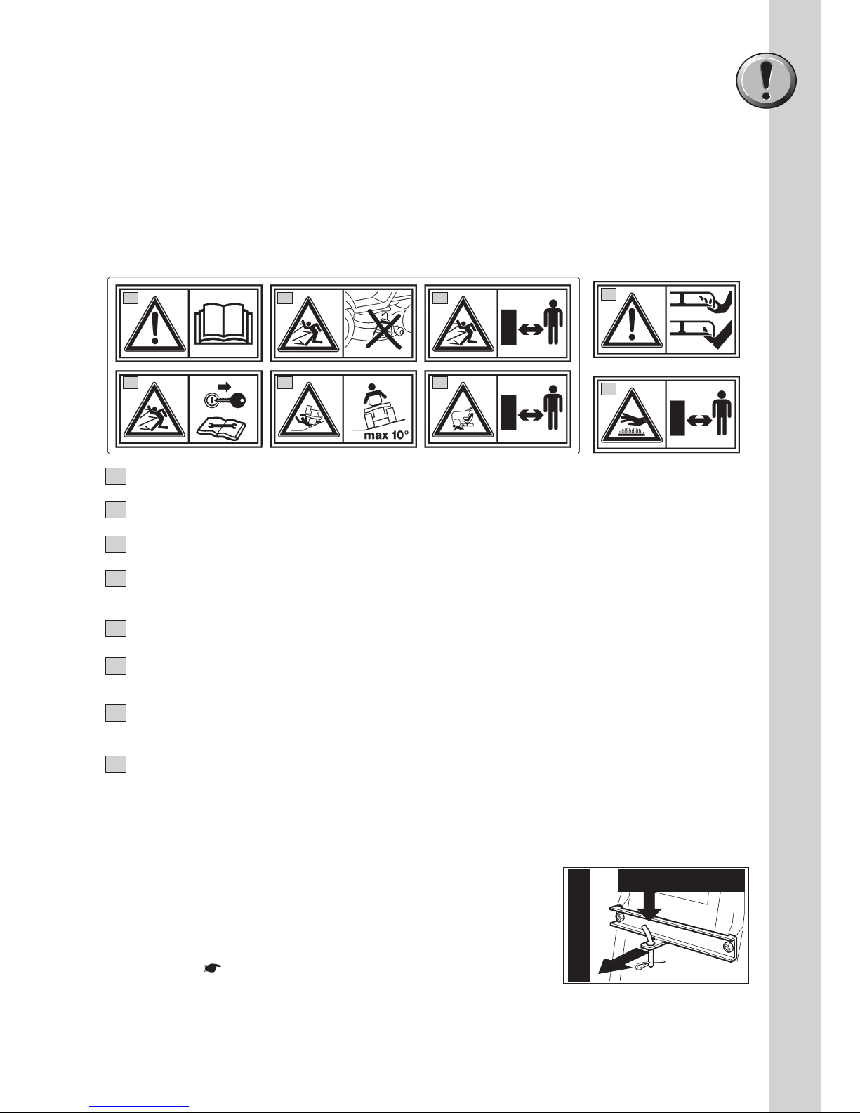
2) Mow only in daylight or good artificial light.
3) Before starting the engine, disengage the blades and shift into neutral.
4) Do not use on slopes of more than 10 Degrees.
5) Remember there is no such thing as a “safe” slope. Travelling on grass slopes
requires particular care. To guard against overturning:
– do not stop or start suddenly when going up or downhill;
– engage the drive slowly and always keep the machine in gear, especially when
travelling downhill;
– machine speeds should be kept low on slopes and during tight turns;
– stay alert for humps and hollows and other hidden hazards;
– never mow across the face of the slope.

3
6) Use care when pulling loads or using heavy equipment:
– use only approved drawbar hitch points;
– limit loads to those you can safely control;
– do not turn sharply. Use care when reversing;
7) Disengage the blades before crossing surfaces other than grass.
8) Never use the machine with damaged guards, or without the safety
protective devices in place.
9) Do not change the engine governor settings or overspeed the engine as it
may void engine & product warranty. Operating the engine at excessive speed can
increase the risk of personal injury and may void warranty.
10) Before leaving the driving seat:
– disengage the blades and lower the attachments;
– go into neutral and apply the parking brake;
– stop the engine and remove the ignition key.
11) Disengage the blades, stop the engine and remove the ignition key:
– before cleaning, checking or servicing the machine;
– after striking a foreign object. Inspect the machine for damage and make repairs
before restarting and operating the machine;
– If the machine starts to vibrate abnormally (check for the causes immediately).
12) Disengage the blades for transport or whenever they are not in use.
13) Stop the engine and disengage the blades:
– before refuelling;
14) Reduce the throttle during engine run-out. If the engine is provided with a shut-off
valve, cut off the fuel when you have finished mowing.
D) MAINTENANCE AND STORAGE
1) Keep all nuts, bolts and screws tight to be sure the equipment is in safe working
condition.
2) Never store the equipment with petrol in the tank inside a building where fumes
may reach an open flame or spark.
3) Allow the engine to cool before storing in any enclosure.
4) To reduce fire hazards, keep the engine, silencer, battery compartment and petrol
storage area free of grass, leaves, or excessive grease.
5) Replace worn or damaged parts for safety purposes.
6) If the fuel tank has to be drained, this should be done outdoors.
7) On multi-bladed machines, remember that the rotation of one blade can cause
other blades to rotate.
8) When the machine is to be stored or left unattended, lower the cutting deck.
1. SAFETY (cont.)

4
1.4 REGULATIONS FOR TOWING
A kit for towing a small trailer is supplied on some models.
This accessory is to be fitted following the instructions
provided.
When using the towing kit, do not exceed the
recommended loads stated on the label & follow the safety
instructions ( 1.2, C-6).
1Warning: Read the instructions before operating this machine.
2Danger! Ejected objects: Do not operate without the stone-guard in place.
3Danger! Ejected objects: Keep bystanders away.
4Warning: Disconnect the ignition key and read the instructions before carrying out any
repair or maintenance work.
5Danger! Machine rollover: Do not use this machine on slopes steeper then 10°.
6Danger! Dismemberment: Make sure that children stay clear of the machine at all time
when engine is running.
7
Danger of cutting yourself. Blades in movement.
Do not put hands or feet near or under the opening of the cutting plate.
8
Warning! - Keep away from hot surfaces.
123
456
max 245 N (25 kg)
max 980 N (100 kg)
7
8
1.3 SAFETY LABELS
Your machine must be used with care. This is why labels with illustrations have
been placed on the machine, to remind you of the main precautions to take during
use.
These labels are to be considered an integral part of the machine.
Should a label come off or become illegible, contact your dealer to replace it.
Their meaning is explained below.

5
18
2
3
4567
18
2
3
4567
18
2
3
4567
2.1 IDENTIFICATION OF THE MACHINE
The label located near the battery housing
has the essential data of each machine.
1. Brand Marking
2. Model Number
3. Barcode Number
4. Date of Manufacture
5. Serial Number
6. Article Number
7. Noise Rating according to
Manufacturer test standard
8. C-Tick Logo denoting EMC compliance
2. IDENTIFICATION OF THE MACHINE & COMPONENTS
16 17 14
1311
15
12
Write your machine’s serial number here (5)
2.2 IDENTIFICATION OF MAIN COMPONENTS
The main components of the machine have the following functions:
11. Cutting deck: this is the guard
housing the rotating blades.
12. Blades: these are what cut the
grass. The wings at the ends help
convey the cut grass towards the
collector channel.
13. Stone-guard or deflector: It is a
safety guard which prevents objects
drawn up by the blades from being
thrown outside of the machine.
14. Engine: this moves the blades and drives the wheels. Its specifications and
regulations for use are described in a specific manual.
15. Battery: provides the energy for starting the engine.
16. Driving seat: this is where the machine operator sits. It has a sensor
connected to safety devices for detecting the presence of the operator.
17. Regulation and safety labels: give reminders on the main regaulations for
working safely, each of which is explained in chapter 1.

6
For storage and transport purposes, some components of the machine are not
installed in the factory and have to be assembled after unpacking. Follow the
instructions below.
IMPORTANT The machine is supplied without engine oil or fuel. Before
starting the engine, fill with oil and fuel following the instructions given in the
engine manual.
WARNING! Unpacking and completing the assembly should be
done on a flat and stable surface, with enough space for machine handling
and its packaging, always making use of suitable equipment.
3.1 UNPACKING
When unpacking the machine, take care to gather all individual parts and fittings,
and do not damage the cutting deck when taking the machine off the pallet.
The packaging contains:
– the machine;
– the steering wheel;
– the dashboard cover;
– the seat;
– the battery;
– the stone-guard;
– the front bumper
NOTE Only some model are supplied inclusive of some kits
such as the Mulching Plug, Tow Hitch and Battery Charger. These kits will
require assembly according to the instructions and are not factory fitted.
NOTE To prevent damage to the cutting deck, raise it to its
maximum height and take upmost care when taking the machine off the pallet.
Hydrostatic transmission To make it easier to get the machine off
the pallet and to move it, the drive disengage lever should be put in position
«B» ( 4.33).
Disposal of the packaging should be done in accordance with the local
regulations in force.
3.2 FITTING THE STEERING WHEEL
Put the machine on a flat surface & straighten up
the front wheels.
Mount the hub (1) on the shaft (2), making sure
that the plug (3) is correctly fitted into the hub seat.
Fit the dashboard cover (4) clicking the seven
fasteners into place.
3. UNPACKING AND ASSEMBLY
1
2
3
4
– an envelope containing:
– the operator’s manuals & documents,
– steering wheel assembly parts,
– nuts and bolts to assemble the seat & the
stone-guard,
– the connection screws for the battery cables
– 2 starter keys,
– 1 spare 10 A fuse.

7
First connect the red wire (3)
to the positive pole (+) and
then the black wire (4) to the
negative pole (–), using the
screws supplied as shown.
Apply silicone grease to the
terminals and check that the
protective cap for the red wire
(8) is in place.
IMPORTANT Always fully charge the battery according to the instructions
in the battery’s manual ( 6.2.5).
IMPORTANT To prevent the safety device in the electronic circuit board
from cutting in, never start the engine until the battery is fully charged!
WARNING! Do not use the machine without the spring (2) or with the
battery incorrectly fixed in its housing.
2
3
3
1
5
1
6
7
8
123
4
5
3. UNPACKING AND ASSEMBLY (cont.)
Fit the steering wheel (5) onto the
hub (1) with the spokes directed
towards the seat.
Fit the spacer (6) and fasten the
steering wheel in place using the
screws supplied (7), in the indicated
order.
Fit the steering wheel cover (8)
clicking the three fasteners into place.
3.3 FITTING THE SEAT
Mount the seat (1) on the plate (2)
using the screws (3).
3.4 ASSEMBLY & CONNECTING
THE BATTERY
The battery (1) is housed under the
seat and secured by a spring (2).

8
3.6 FITTING THE SIDE DISCHARGE CHUTE (STONE GUARD)
Inside the stone-guard (1), fit the spring (2) by inserting
the terminal (2a) into the hole and turning it so that both
the spring (2) and the terminal (2a) are securely
positoned in their seatings.
Position the stone-guard (1) in line with the cutting deck
brackets (3). Using a screwdriver, turn the second
terminal (2b) of the spring (2) to bring it outside the
stoneguard.
Fit the pin (4) in the holes on the
brackets (3) & on the stone-
guard, so that it passes thrugh
the coils of the spring (2) & the
drilled end comes out of the inner
most bracket.
Fit the cotter pin (5) in the hole
(4a) of the pin (4) & turn the pin
until the two ends (5a) of the split
pin can be bend (using pliers), so
that it cannot slip out and let the
pin fall out (4).
WARNING!
Check that the spring works correctly and keep the stone-guard securely lowered.
Make sure that the pin is fitted properly to prevent it from falling out accidently.
Do not use the machine without the Side Discharge Chute (Stone -Guard) (1)
correctly fitted. The Side Discharge Chute must be fitted at all times, regardless of
the use of a mulching plug.
3.5 FITTING THE FRONT BUMPER
Fit the Front Bumper (1) onto the chassis
mounting holes (5) and fasten in place
using screws (2) four places.
Note that access can be improved by
temporarily removing the Hood Bonned from
the Hinge (3), or by turning the steering
wheel to adjust the position of the wheel (4).
WARNING! Do not use the
machine without the Front Bumper (1)
correctly fitted to the chassis (5)!
171505434/0
2
3
5
4
1
2b
1
3
2b
1
4
3
2
4a
5
45a
1
2
2a
2
2
2b
1
3
2b
1
4
3
2
4a
5
45a
1
2
2a
2
2
2b
1
3
2b
1
4
3
2
4a
5
45a
1
2
2a
2
2

9
3.7 REPOSITIONING THE
ANTI-CHIPPING WHEELS
For transport reasons, the anti-
chipping wheels (1) are fastened on
the top hole. In order for them to
work properly, the anti-chipping
wheels (1) must be repositioned in
the hole which is most suited for the
type of ground ( 5.4.5).
3.8 FITTING & USING THE MULCHING PLUG (OPTIONAL)
NOTE The mulching
plug kit is not supplied as standard
on all models. The mulching plug kit
is not factory assembled.
WARNING! Always fit &
dismantle the accessory with the
engine off, after removing the
ignition key and engaging the
parking brake. You always need to
work with the stone-guard fitted
properly even when using the
mulching plug accessory.
To fit, lift the stone-guard & place the
mulching plug over the cutter deck
opening.
Ensure the inner rib (2) of the Mulching
Plug locates inside the opening of the
cutter deck.
Roll the mulching plug into place so
that the rib (1) inserts beneath the
stone guard hinge (3).
Insert bolt from underside of cutter
deck, through the plug and secure on
topside using pin clip.
Before use or turning on the machine,
check that the plug is secure.
1
3. UNPACKING AND ASSEMBLY (cont.)
1
2
3
4

10
For a sound operation, mow the lawn frequently and regularly to reduce the height
of the grass.
Always avoid removing a large
quantity of grass, to avoid
blocking the cutting deck or
overloading the engine and the
cutting parts.
Regulate the forward speed
depending on the lawn
conditions and the quantity of
grass removed. The cutting
deck mulching plug recycles
grass inside the cutting deck,
chopping it into fine strands
and strewing them evenly on
the lawn.
The grass cuttings are left on the lawn, protecting it from drying out during
heatwaves. These finely chopped grass cuttings decompose quickly, nourishing
the soil.
3.9 FITTING THE TOW HITCH
(OPTIONAL)
When using the towing kit, do not
exceed the recommended loads (
1.4) & follow the safety
instructions ( 1.2, C-6 & 1.4).
NOTE
The tow hitch kit is not supplied as
standard on all models.
The tow hitch kit is not factory
assembled.
To fit, remove two mounting hole caps
(1) by knocking out with a hammer &
pin.
Insert two mounting bracket studs (2)
through each mounting hole so that the
stud protrude outwards from the rear of
the machine.
Mount the main tow hitch bracket (3)
over the two mounting bracket studs (2)
and secure in place with nuts (4).
max 245 N (25 kg)
max 980 N (100 kg)
1
2
3
4
MULCHING
SIDE EJECT

11
4.1 STEERING WHEEL
Turns the front wheels.
4.2 THROTTLE
This regulates the engine's r.p.m.
The positions are indicated on a
plate showing the following sym-
bols:
«CHOKE» cold starting
«SLOW» for minimum engine
speed
«FAST» for maximum engine
speed
4. CONTROLS AND INSTRUMENTS
4.21-4.31
4.31
4.3
1
4.22
4.1
4.2
4.6
4.32
4.4
4.2a
4.5
4.2
4.2a
– The «CHOKE» position enriches the mixture so must
only be used for the time necessary when starting
from cold.
– When moving from one area to another, put the lever
in a position between «SLOW» and «FAST».
– When cutting, shift into «FAST».
4.2a CHOKE CONTROL (if fitted)
It enriches the mixture and must only be used for the necessary time for cold
starting.
4.3 KEY IGNITION SWITCH
This key operated control has four positions:
«OFF» everything is switched off;
«HEADLIGHTS ON» (if fitted);
«ON» activates all parts;
«START» connects the starter motor.
– If you release the key on «START», it will automatically return to «ON».
– After turning the engine on, turn the lights on
(if fitted) by turning the key to the
«HEADLIGHTS ON» position.
– to switch them off, turn the key to «ON».
4.3

12
4.5 BLADE ENGAGEMENT AND BRAKE CONTROL
The mushroom switch allows you to engage the blades using the electromagnetic
clutch:
«A» Pressed = Blades disengaged
«B» Pulled = Blades engaged
– If you engage the blades without taking the
necessary safety precautions, the engine shuts
down and cannot be restarted ( 5.2).
– Blade disengagement (Pos. «A»), simultaneously
activates a brake which stops their rotation in a few
seconds.
4.4 PARKING BRAKE
This brake stops the machine from moving when it has been parked.
There are two positions:
«A» = Brake off
«B» = Brake on
– The brake is applied by pressing the pedal right
down (4.21 or 4.31) and moving the lever to
position «B». When you take your foot off the
pedal it will be blocked by the lever in the
lowered position.
– To disengage the parking brake, press the pedal (4.21 or 4.31). The lever will
return to position «A».
B
A
4.4
4.5
A
B
4.6 CUTTING HEIGHT ADJUSTMENT LEVER
There are seven positions for this lever (shown as
«1» to «7» on the label), which correspond to
various heights between 3 and 8 cm.
– To go from one position to another, move the
lever sideways and put it back in one of the stop
notches.
Mechanical transmission
4.21 CLUTCH / BRAKE PEDAL
This pedal has two functions: during the first part of its
travel it acts as a clutch, engaging and disengaging
drive to the wheels, and in the second part it acts as a
brake on the rear wheels.
IMPORTANT
Do not keep the pedal halfway between clutch engagement or disengagement, as
this can cause overheating and damage the transmission belt.
NOTE When the machine is moving, keep your foot off the pedal.
4.6
1
7
4.21

13
4.22 SPEED CHANGE LEVER
This lever has seven positions for the 5 forward
speeds, the neutral position «N», and reverse «R».
To go from one speed to another, press the pedal
(4.21) halfway and shift the lever as shown on the
label.
WARNING! Only shift into reverse when
the machine has stopped moving.
Hydrostatic transmission
4.31 BRAKE PEDAL
This pedal works the brake on the rear wheels.
4.32 DRIVE PEDAL
This pedal engages drive in the wheels &
controls the machine’s forward & reverse speeds.
– To engage forward drive, press it towards «F»
with your toecap. As you increase the pressure
on the pedal, the speed of the machine
increases.
– Reverse is engaged by pressing the pedal with
the heel towards «R».
– The pedal automatically goes into neutral «N»
when released. speeds.
4.22
5
R
2
3
4
N
1
4.31
4.32
R
N
F
WARNING! Only shift into reverse when the machine has stopped
moving.
NOTE If the drive pedal is used, whether forwards or for reverse,
the engine stops as soon as the parking brake (4.4) is engaged.
4.33 HYDROSTATIC TRANSMISSION DISENGAGEMENT LEVER
This lever has two positions:
«A» = Transmission engaged: for all
uses, when moving & during cutting;
«B» = Transmission disengaged: this
makes it much easier to move the
machine by hand, with the engine
turned off.
IMPORTANT To avoid damage to the transmission unit, this operation
must be carried out only when the engine has stopped with the pedal (4.32)
on position «N».
4.33
A
B
4. CONTROLS (cont)

14
5.1 SAFETY RECOMMENDATIONS
DANGER! The machine must only be used for the purpose for which
it was designed (cutting grass). Using the machine in any other way is
considered “improper use” which will invalidate the warranty, relieve the
manufacturer from all liabilities, and the user will consequently be liable for all
and any damage or injury to himself or others.
Examples of improper use may include, but are not limited to:
– transport people, children or animals on the machine or on a trailer;
– tow or push loads without the use of the specified accessory for towing;
– use of the machine for moving over unstable, slippery, icy, stony, rough,
marshy ground and puddles that do not allow for evaluation of the
consistency of the ground;
– use of the blades on surfaces other than grass.
DANGER! Do not tamper with or remove the safety devices fitted on
the machine. REMEMBER THAT THE USER IS ALWAYS RESPONSIBLE FOR
DAMAGE AND INJURY TO OTHERS. Before using the machine:
– read the general safety regulations ( 1.2), paying particular attention to
driving and cutting on slopes;
– carefully read the instructions for use, make sure you are familiar with the
controls and know how to stop the blades and the engine quickly;
– never put your hands or feet next to or beneath the rotating parts and always
keep away from the exit.
Do not use the machine when in a precarious state of health or under the effect
of medicine or any other substances that can reduce your reflex actions and
your ability to concentrate.
It is the user’s responsibility to assess the potential risk of the area where work
is to be carried out, and to take all the necessary precautions to ensure his own
safety and that of others, particularly on slopes or rough, slippery and unstable
ground.
Do not leave the machine on high grass with the engine running to avoid the risk
of starting a fire.
5. HOW TO USE THE MACHINE
WARNING! This machine must not be used on slopes steeper than 10
Degrees ( 5.5).
IMPORTANT All the references relating to the positions of controls are
described in chapter 4.
5.2 WHY THE SAFETY DEVICES CUT IN
The safety devices work in two ways:
– they prevent the engine from starting if all the safety requirements have not been
met;
– they stop the engine if even just one of the safety requirements is lacking.
a) To start the engine, it is necessary that:
– the transmission is in “neutral”;
– the blades are not engaged;
– the operator is seated or the parking brake is engaged.

15
b) The engine stops when:
– the operator leaves his seat when the blades are engaged;
– the operator leaves his seat when the transmission is not in “neutral”;
– the operator leaves his seat with the transmission in “neutral” but without apply-
ing the parking brake;
– the parking brake is engaged without disengaging the blades.
– the speed change is activated ( 4.22) or the drive pedal
(4.32) with the parking brake on.
5.3 DIRECTIONS BEFORE STARTING WORK
Before starting to mow, it is necessary to carry
out several checks and operations to ensure you
can work efficiently and in maximum safety.
5.3.1 Seat adjustment
To change the seat position, loosen the four
fixing bolts (1) and slide it along the slots.
Once you have found the right position, tighten
the four screws (1).
5.3.2 Tyre pressure
1
1
Having the right tyre pressure is the main condition for ensuring that the cutting
deck is horizontal and mows evenly.
Unscrew the valve caps and connect a compressed air line with a gauge to the
valves and adjust the pressure to the indicated values.
5.3.3 Filling with oil and fuel
NOTE The engine manual
indicates what type of oil and fuel you
can use.
With the engine off, check the oil level.
According to the instructions in the engin
manual, this must be between the MIN an
MAX marks on the dipstick.
17.4 psi / 1,2 bar
(15 inch Ø)
(13 inch Ø)
14.5 psi / 1,0 bar
21.7 psi / 1,5 bar
MAX
MIN
5. HOW TO USE THE MACHINE (cont)

16
Refuel using a funnel, but do not completely fill the tank.
The tank's capacity is about 6.5 liters.
DANGER! Refuelling should be carried out in an open or well
ventilated area with the engine off. Always remember that petrol fumes are
inflammable. DO NOT USE A NAKED FLAME TO LOOK INSIDE THE TANK
& DO NOT SMOKE WHEN REFUELLING.
IMPORTANT Do not drip petrol onto the plastic parts to avoid
damaging them. In the event of accidental spills or leaks, rinse immediately
with water. The warranty does not cover for damage to plastic parts of the
bodywork or the engine caused by petrol.
5.3.4 Checking the protection at the
exit (stone-guard)
WARNING! Never use the
machine without the exit guards or
when the guards are damaged!
Always check that the inner spring of the
stone-guard (1) works properly, whilst
keeping it securely lowered.
5.3.5 Checking machine safety and efficiency
1. Check that the safety devices function as described ( 5.2).
2. Check that the brake is in perfect working order.
3. Do not start mowing if the blades vibrate or if you are unsure whether they are
sharp enough. Always remember that:
– A badly sharpened blade pulls at the grass and causes the lawn to turn yellow.
– A loose blade causes unwanted vibrations and can be dangerous.
WARNING! Do not use the machine if you are unsure whether it is
working safely or efficiently. If in doubt, contact your Dealer immediately to
make the necessary checks and repairs.
1

17
5.4 USING THE MACHINE
5.4.1 Starting
DANGER! The engine must be started in an open or well-ventilated
area! ALWAYS REMEMBER THAT EXHAUST GASES ARE TOXIC!
To start the engine:
– open the fuel tap (1);
– shift in the gear into neutral («N») ( 4.22 or
4.32);
– disengage the blades ( 4.5);
– apply the parking brake on sloping ground;
– for cold starting, operate the choke ( 4.2 or
4.2a);
– if the engine is already warm, position the lever between «SLOW» and «FAST»;
– put in the ignition key and turn to «ON» to make electrical contact, then turn to
«START» to start the engine;
– release the key once the engine has started.
When the engine has started, move the throttle to «SLOW».
IMPORTANT The choke must be closed as soon as the engine is
running smoothly. Using it when the engine is already warm can foul the spark
plugs and cause the engine to run erratically.
NOTE If there are engine starting problems, do not insist as you
can risk running the battery flat and flooding the engine. Turn the key to «OFF»,
wait for a few seconds and then repeat the operation. If the malfunction
persists, refer to the engine manual and chapter «8» in this manual.
1
IMPORTANT Always bear in mind that the safety devices prevent the
engine from starting if safety requirements have not been met ( 5.2).
In these cases, once the situation has been corrected, the key must first be
turned back to «OFF» before the engine can be restarted.
5.4.2 Starting and moving without mowing
WARNING! This machine has not been approved for use on public
roads. It has to be used (as indicated by the highway code) in private areas
closed to traffic.
When moving the machine:
– disengage the blades;
– bring the cutting deck to the highest position (position «7»);
– put the accelerator control between the «SLOW» and «FAST» positions.
Mechanical transmission
Push the pedal down as far as possible ( 4.21) and move the gear change lever
into 1st gear ( 4.22). Keep the pedal pressed down and release the parking
brake. Slowly release the pedal to shift from «brake» to «clutch», thus operating the
rear wheels ( 4.21).
5. HOW TO USE THE MACHINE (cont)
This manual suits for next models
1
Table of contents
Other Kioti Lawn Mower manuals