- 2 -
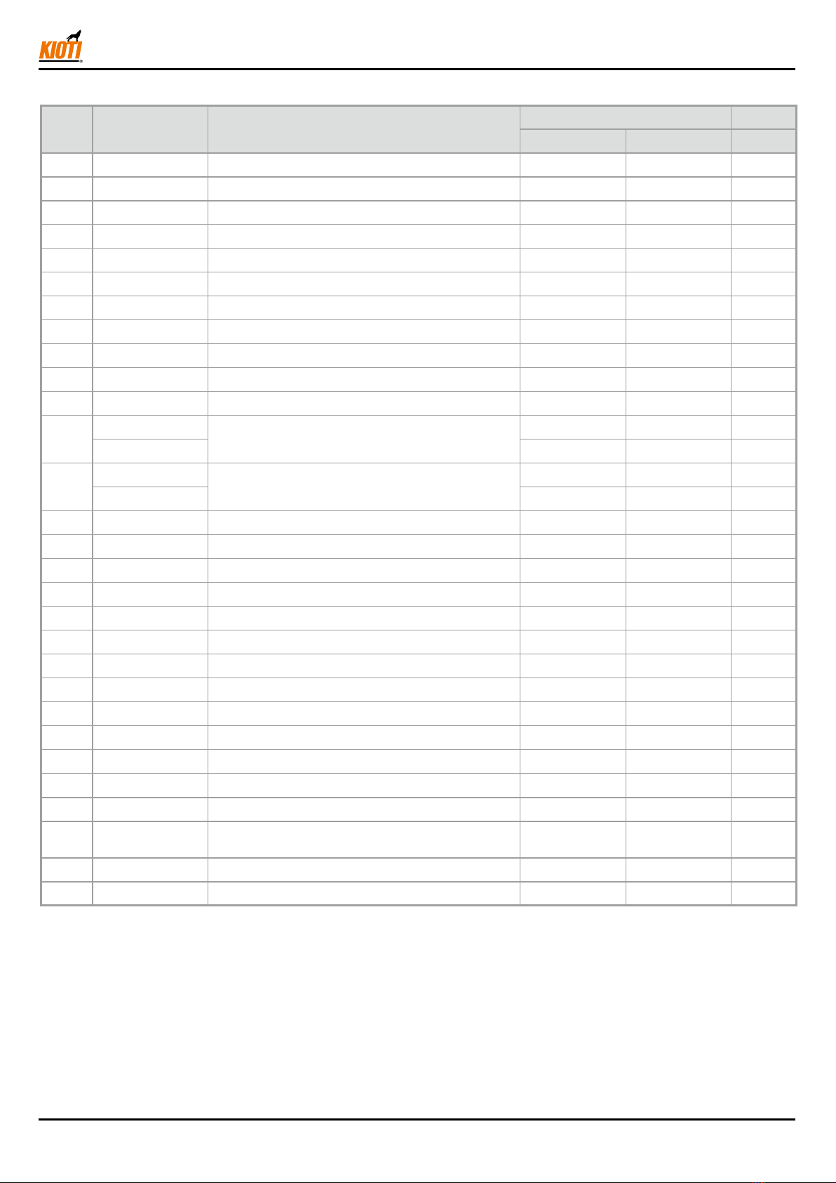
1. PACKING LIST & ACTUAL IMAGE
NO. Part No. Description Q'TY Remark
UD25-A0008A UD25-A0009A
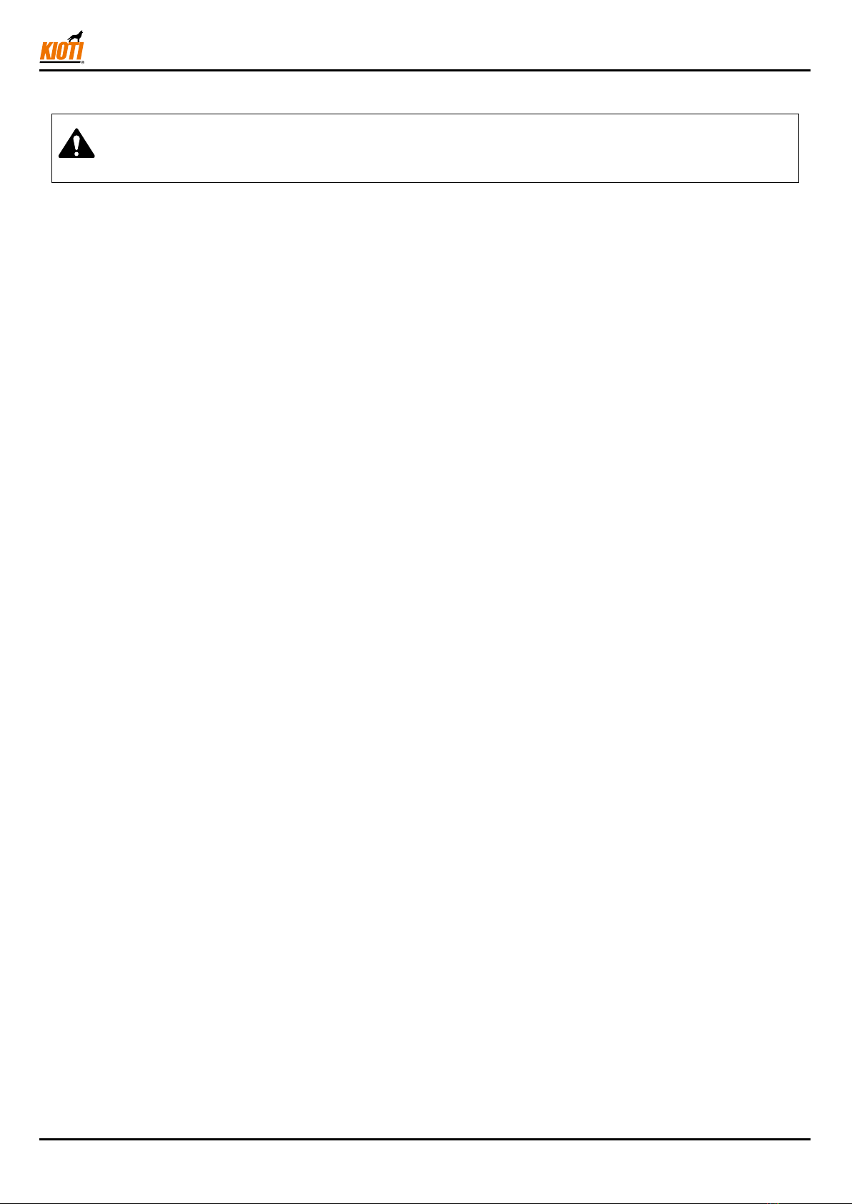
1 U3400-34211 HYDRAULIC VALVE ASS`Y - C 1 1
2 U3215-32252 ADAPTOR - CONTROL VALVE 1 1
3 05411-00630A PIN, SPRING 1 1
4 T4810-46971 TUBE, CONNECTING 1 1
5 T4715-47071 TUBE, CONNECTING 1 1
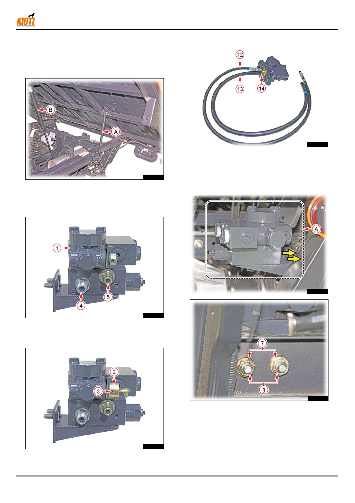
6 T2350-66161 ELBOW 2 2
7 04512-50100A WASHER, SPRING 2 2
8 02176-50100A NUT 3 3
9 UD25-0012B ASS`Y HOSE, CYLINDER HYDRAULIC - A 1 1
10 UD25-0013A ASS`Y HOSE, CYLINDER HYDRAULIC - B 1 1
11 T2198-82561 BAND, CORD 1 1
12 UD25-0007A ASS`Y HOSE, HYDRAULIC - C1 1 -
UD25-0030A - 1
13 UD25-0002A HOSE, DRAIN 1 -
UD25-0027A - 1
14 F6800-91851 BAND, HOSE 2 2
15 T2198-82561 BAND, CORD 4 1
16 UD25-0017A ASS`Y CYLINDER, HYDRAULIC - DUMP 1 1
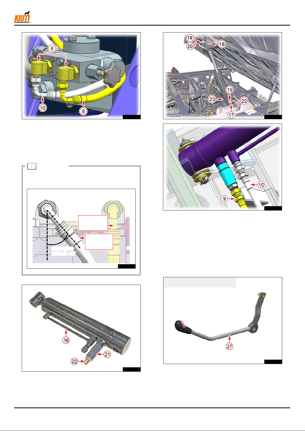
17 UD25-0016A PIN, CYLINDER 1 1
18 U3215-32972 PIN, JOINT 1 1
19 04013-50200A WASHER, PLAIN 4 4
20 05515-51600A PIN, SNAP 2 2
21 U3215-32001 ORIFICE 1 1
22 T4620-66161 TUBE, CONNECTING 1 1
23 06613-10010A NIPPLE, GREASE 1 1
24 T2610-39882 GRIP 1 1
25 UD22-12ACB HYDRAULIC LEVER COVER ASS`Y 1 1
26 U3215-81552 SCREW 2 2
27 UD22-
11AAA.03 DUMP LEVER ASS`Y, COMPLETE 1 -
28 U3215-85711 LABEL WARNING, HYDRAULIC LEVER LOCK 1 1
29 U3215-85491 LABEL, DOUBLE ACTING LEVER ENG 1 1