Kistler-Morse STXplus User manual

CAUTION
It is essential that all instructions in this
manual be followed precisely to ensure
proper operation of the equipment.
STXplus Signal Transmitter
Installation and Operation Manual
97-1180-01
Revision G
Jan 2012
O
Or
rd
de
er
r
f
fr
ro
om
m:
:
C
C
A
A
B
Br
ri
ig
gg
gs
s
C
Co
om
mp
pa
an
ny
y
622 Mary Street; Suite 101; Warminster, PA 18974
Phone: 267-673-8117 - 800-352-6265; Fax: 267-673-8118

NOTICE
The content of this document is the intellectual property of Kistler-Morse®. Any reproduction
or translation of this document wihtout the written authorization of Kistler-Morse®is strictly
prohibited.
CAUTION
Follow these rules if welding is done on the vessel after installation of Kistler-Morse®
sensors/transducers. The electrical current of the welder may pass through the
sensor/transducer, causing damage to it and possibly to the signal processor. To avoid
damage, follow these precautions:
1. Disconnect the sensor/transducer cables from the signal processor.
2. Ground the welder as close to the welding joint as possible. The welding ground must be
between the sensor/transducer and the weld joint to prevent the welding current from going
through the sensor/transducer to earth ground.
NOTE
High temperatures can damage sensors/transducers. If you are welding in the vicinity of a
sensor/transducer, monitor the temperature of the metal adjacent to the sensor/transducer. If it
becomes too hot to touch, stop welding immediately and remove the sensor/transducer before
continuing. Prior to reinstalling the sensor/tranducer, verify that no damage has occurred.
This manual reects STXplus Software Revision B. If you have a previous revision, please
contact Kistler-Morse®.

TABLE OF CONTENTS
CHAPTER 1: INTRODUCTION 1-1
Introduction 1-1
Physical Description 1-1
Functional Description 1-1
Analog Mode 1-1
Filters 1-1
LEDs 1-1
Manual Conventions 1-1
CHAPTER 2: HARDWARE INSTALLATION 2-1
General Information 2-1
Unpacking and Inspection 2-1
Mounting STXplus 2-1
Stand-Alone STXplus with Customer-Supplied Panel/Enclosure 2-1
Stand-Alone STXplus with Kistler-Morse®Supplied Enclosure 2-1
Drilling Holes in the Enclosure 2-1
Wiring System 2-2
Wiring Junction Box to STXplus 2-2
Wiring Power 2-2
Wiring Current Output 2-2
External Current Loop Power Supply 2-2
Sealing Openings in Stand-Alone STXplus Enlcosure 2-2
Quick Reference 2-3
Default 2-3
Changing the Modbus or Serial Port Address 2-3
Changing from Half-Bridge 3-Wire to Full-Bridge 4-Wire 2-3
Enabling Remote Sense 2-3
Enabling Remote Loop Voltage for the 0-20mA/4-20mA 2-3
EnablingtheModbus5.11kΩPull-UpResistorandthe12kΩEnd-Of-LineResistor 2-4
Changing from RS-422 to RS-485 2-4
4-20mA Output 2-4
CHAPTER 3: STAND-ALONE ANALOG CALIBRATION AND SET UP 3-1
Introduction 3-1
Trimming the Current Output 3-1
Trim the 0mA Current Output 3-1
Trim the 4mA Current Output 3-1
Trim the 20mA Current Output 3-1
Setting Up Current Ouptut Operating Mode (0-20mA or 4-20mA) 3-2
Setting Up Input Voltage Range 3-2
Setting Up Channel Enable 3-2
Analog Calibration 3-3
High-Accuracy Calibration 3-3
Starting with an Empty Vessel 3-3
Starting with a Full Vessel 3-4
Calibration by Adding a Known Quantity of Material 3-5
Calibration by Subtracting a Known Quantity of Material 3-5

System Set Up 3-6
Descriptions 3-6
Current Output Range 3-6
Current Output Tracking 3-6
Current Output Fail-safe 3-6
LO Span and HI Span 3-6
0mA, 4mA, and 20mA Trim 3-6
Serial Port 1 Baud Rate/Protocol 3-6
Averaging Factor 3-6
DSP Filter 3-7
DSP Enable 3-7
DSP Step 3-7
Input Voltage Range 3-7
Modbus Baud Rate 3-7
Channel Enable 3-7
Tare 3-8
APPENDIX A: PRODUCT SPECIFICATIONS A-1
APPENDIX B: KISTLER-MORSE® PROTOCOL SERIAL COMMANDS B-1
Introduction B-1
Command Table B-1
Checksum Calculation B-4
Examples B-5
APPENDIX C: MODBUS PROTOCOL SERIAL COMMANDS C-1
Introduction C-1
Modbus Implementation C-1
Modbus Function Codes C-3
Modbus Exception Responses C-5
Commands C-6
Important Points C-7
Modbus Memory Map Table C-8
APPENDIX D: TECHNICAL DRAWINGS D-1
TI-SP.STXP-01 D-2
TI-SP.STXP-02 D-3
TI-STXPlus.Varistor D-8

CHAPTER 1: INTRODUCTION
INTRODUCTION
The STXplus Signal Transmitter, shown
above, is a 4-channel signal processor that
receives an analog input from strain gage
sensors/transducers and provides 2-5A
ouput relays, current, and serial output. The
STXplus has a 23-bit analog-to-digital (A/D)
converter that provides high resolution.
PHYSICAL DESCRIPTION
TheSTXplusPCBcanbeconguredin
several ways:
1. STXplus in Kister-Morse®
Supplied Enclosure. The STXplus PCB is
housed in a NEMA-rated enclosure and
wall-mounted near the vessel. An
optional AC power supply can be
purchased, or customer-supplied DC
power can be used.
2. STXplus in a Customer-Supplied
Panel/Enclosure. An optional AC
power supply can be purchased, or
customer-supplied DC power can
be used.
FUNCTIONAL DESCRIPTION
Analog Mode
The STXplus can receive an analog signal
from either half-bridge sensors/transducers
(Load Cell, Microcell, Load Stand II,
and Load Disc II) or from full-bridge
sensors/transducers.
The analog engine is calibrated using the
calibration buttons. When in Analog Mode,
current output from the STXplus PCB is
controlled by the analog engine.
Filters
The STXplus has several features which help
provide stable output. The Sentry™ DSP
Filter reduces output changes that can result
from vibration.
LEDs
Com 1 LEDs TXD2, RXD2
Modbus LEDs TXD1, RXD1
15V D3
5V Isolation for Current D29
Output
Programming Parameter D15-D18
Programming Value D19-D22
Relay 1 D13
Relay 2 D11
4-20mA Current Output D30
5V Analog Voltage D26
Manual Conventions
WARNING!
Possible danger to people. Injury may result
if this information is ignored.
CAUTION
Possible risk to the product. The signal
processor or other equipment may be
damaged if this information is ignored.
NOTE
Contains additional information about a step
or feature critical to the installation or
operation of the signal processor.
1-1

CHAPTER 2: HARDWARE INSTALLATION
GENERAL INFORMATION
This chapter provides instructions on how to
install and wire the STXplus. The STXplus
can be installed in several ways.
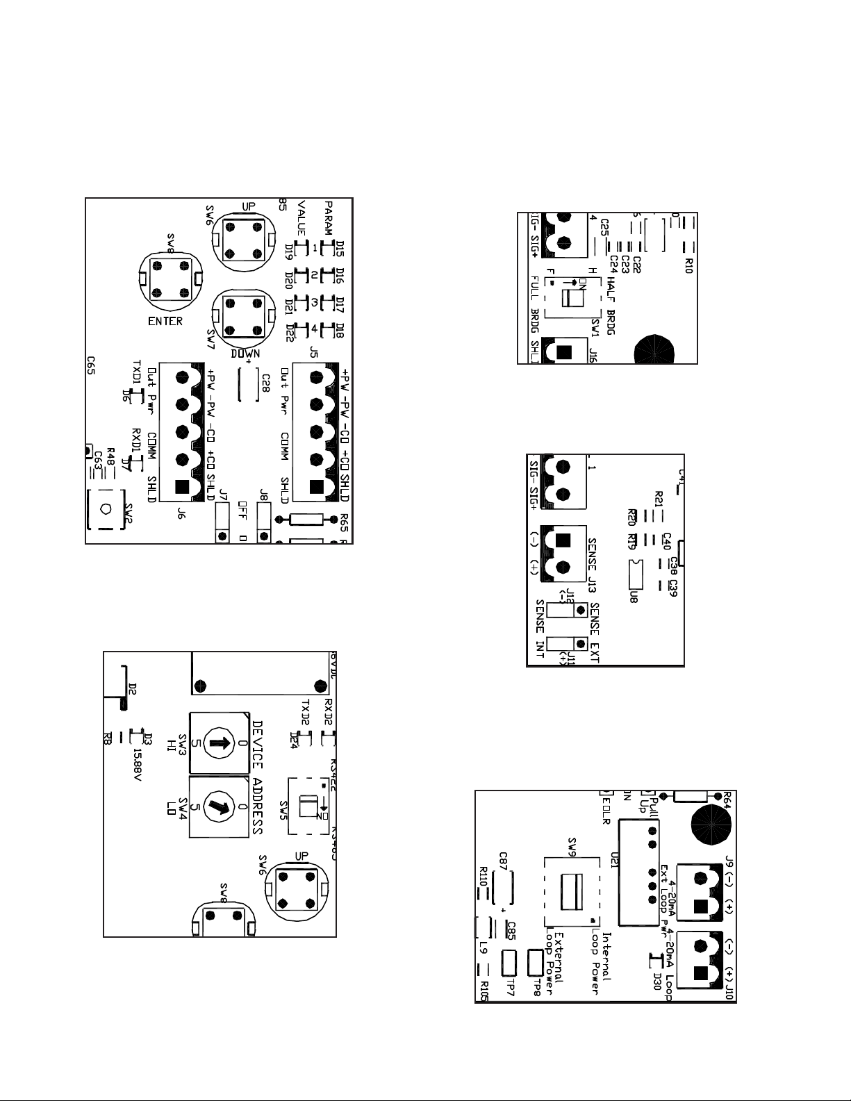
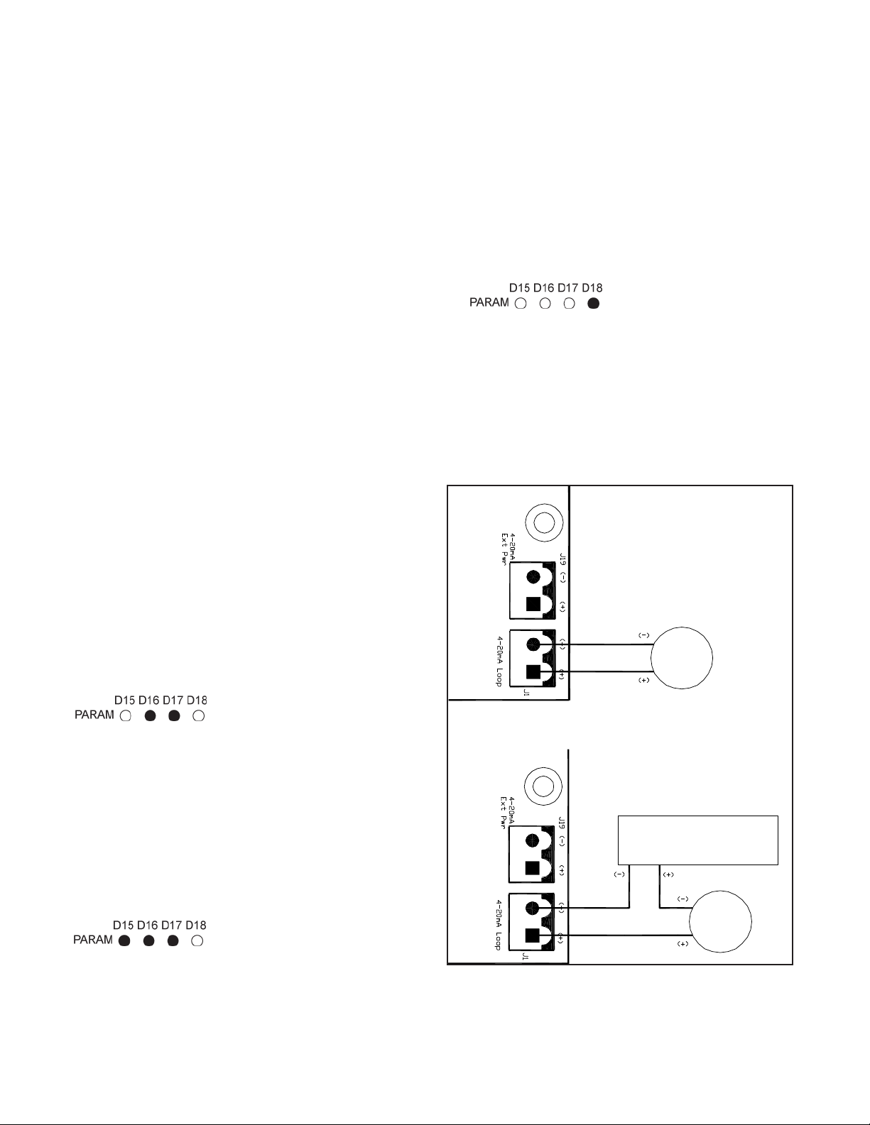
Refer to the drawings in Appendix D for
wiring and installation details.
WARNING!
To prevent equipment damage or personal
injury, once the STXplus has been
connected to power:
1. Disconnect power before wiring
anything to the STXplus, adding or
removing PCBs, or mounting the
stand-alone STXplus.
2. Deactivate power to the controlled
devices.
Review all instructions before beginning
installation. Follow all instructions carefully
to ensure the equipment is properly mounted
and wired.
UNPACKING AND INSPECTION
Carefully remove the STXplus from the
shippingcontainerandplaceitonaat
surface. Visually inspect for damage that
may have occurred during shipment. If any
damage is evident, note it on the shipping
receipt. Report the damage to the carrier
and to a Kistler-Morse®representative
immediately. Store the shipping container
and packing material for later use in the
event the equipment must be returned to
the factory.
MOUNTING THE STXPLUS
Do not mount the STXplus near high power
equipment, contactors, SCR drives, 440V
lines, etc. Refer to Appendix A for
environmentalspecicationsbefore
mounting.
Stand-Alone STXplus with
Customer-Supplied Panel/Enclosure
Mount the STXplus in an enclosure in an area
suitable for the device. The STXplus
dimensions are shown on Drawing
TI-SP.STXP-01 in Appendix D.
Stand-Alone STXplus with Kistler-Morse®
Supplied Enclosure
When mounting the STXplus, be sure there
is enough clearance to open the front door
completely. The enclosure dimensions are
shown on Drawing TI-SP.STX-01 in
Appendix D.
NOTE
Mounting feet are supplied by Kistler-Morse®.
Drilling Holes in the Enclosure
CAUTION
Remove the electronics before drilling
enclosure holes. Drill holes through the
bottom or side of the enclosure. DO NOT
drill holes throught the top as this may allow
moisture seepage, which can damage the
electronics and void the warranty.
Follow this procedure to mount the STXplus:
1. Hold the enclosure against the wall in the
desired location and mark the positions of
the mounting holes. Place the enclosure
in a safe place.
2. Drill the mounting holes in the wall.
3. Attach the enclosure to the wall.
The STXplus NEMA-rated enclosure has no
openings through which to route cables or
install conduit. Before you begin wiring, drill
entry holes through the enclosure where it is
2-1

CHAPTER 2: HARDWARE INSTALLATION
most convenient to route the conduit or
cables. Hole location is critical for proper
PCB installation. Check clearances to ensure
ttingsandwireroutingwillnotinterferewith
the PCB or enclosure door. Refer to Drawing
TI-SP.STXP-01 in Appendix D.
WIRING SYSTEM
This section describes how to wire the
junction box, power, and auxiliary equipment
totheSTXplus.Refertothespecications
in Appendix A and Drawing TI-SP.STXP-02 in
Appendix D.
WARNING!
All wiring must comply with government
or local codes.
Wiring Junction Box to STXplus
CAUTION
Do not route junction box cables in the
same conduit with AC power cables.
NOTE
1. Sealallconduitttingsagainstwater
entry. Install conduit drains at the
conduit’s lowest elevation(s) to allow
condensation to drain.
2. All wiring routed between junction boxes
and STXplus must be continuous
(no splices).
Wiring Power
WARNING!
When connecting power to this unit,
power wiring must comply with the
national wiring requirements for the
country in which the equipment is
installed and the ground conductor must
be connected to the protective earth (PE)
terminal.
See Appendix D (Page D-8) for Installation
Instructions for AC Line Varistors.
Refer to the instructions below and
Appendix D.
DC: STXplus operates on 12-30VDC
power
AC: STXplus operates on 100-240VAC,
47-63Hz
NOTE
The standard lead colors for AC power in
North America are green for ground, black for
hot, and white for neutral.
WIRING CURRENT OUTPUT
External Current Loop Power Supply
The STXplus Current Transmitter Loop is
powered by the STXplus power supply.
However, an external power supply may
be desired for some applications. The
maximum allowable voltage from the
external power supply is 30VDC. The
minimum allowable voltage is based on the
loop resistance, allowing a 2V overhead for
the output’s current sensing.
For example:
1,000Ωx0.2A=20V
Minimumvoltage=20V+2V=22V
Wire the current transmitter external power
supply as shown in Appendix D. Move the
SW9 switch on the STXplus PCB to the
Ext position.
Sealing Openings in the Stand-Alone
STXplus Enclosure
After conduit and cable installation is
complete, seal around the openings in the
STXplus enclosure to prevent moisture
seepage.
CAUTION
Only use Sikaex 1A polyurethane sealant
or Dow Corning RTV 739 or RTV738.
Other sealants may contain acetic acid,
which is harmful to electronics.
2-2

CHAPTER 2: HARDWARE INSTALLATION
QUICK REFERENCE
Default
Hold the UP, DOWN, and ENTER buttons
while pressing the SW2 reset button.
Changing the Modbus or Serial
Port Address
Both the Modbus Port and the Serial Port
share the same switches to set the port.
Changing from Half-Bridge 3-Wire to
Full-Bridge 4-Wire
Half-bridge will have 12V excitation and
full-bridge will have 10V excitation
automatically.
Enabling Remote Sense
The remote sense is used for 6-wire load
cells or when barriers are used.
Enabling Remote Loop Voltage for the
0-20mA/4-20mA
This switch is moved to external loop power
when a separate power supply will be used
to power the current loop.
2-3

CHAPTER 2: HARDWARE INSTALLATION
Enabling the Modbus 5.11kΩ Pull-Up
Resistor and 12kΩ End-Of-Line Resistor
These jumpers enable and disable the
pull-up resisor and the end-of-line resistor.
The pull-up resistor is used where there is a
long cable run causing a loss of
communications. The end-of-line resistor is
used on the last device in the serial chain.
Changing from RS-422 to RS-485
SW5 changes the Serial 1 port protocol from
RS422 to RS485.
4-20mA Output
D30 will light when a device/multimeter is
wired to the current output terminals. The
LED will be much brighter with 20mA and
less bright with 4mA.
2-4

CHAPTER 3: STAND-ALONE ANALOG CALIBRATION AND SET UP
INTRODUCTION
This chapter contains the procedures to
perform an analog calibration and set up
system parameters for the STXplus.
TRIMMING THE CURRENT OUTPUT
Prior to calibration, check and adjust the
current output as necesary. If the
calibration of the device receiving the current
output does not match the calibration of the
current output, follow the appropriate
procedure below to trim the 0mA, 4mA,
and/or the 20mA current output(s).
If the STXplus is off, apply power and let it
warm up for at least 15 minutes before
proceeding.
NOTE
If you do not press a button within
15 seconds, the STXplus exits the
programming mode.
Trim the 0mA Current Output
1. Press the DOWN or UP buttons until the
PARAM LEDs look like:
Press the ENTER button.
2. Press the UP button to adjust the 0mA
up and press the DOWN button to adjust
the0mAdown.Whensatised,pressthe
ENTER button.
Trim the 4mA Current Output
1. Press the DOWN or UP buttons until the
PARAM LEDs look like:
Press the ENTER button.
2. Press the UP button to adjust the 4mA
up and press the DOWN button to adjust
the4mAdown.Whensatised,pressthe
ENTER button.
Trim the 20mA Current Output
1. Press the DOWN or UP buttons until the
PARAM LEDs look like:
Press the ENTER button.
2. Press the UP button to adjust the 20mA
up and press the DOWN button to adjust
the20mAdown.Whensatised,press
the ENTER button.
Figure 3-1. Two Methods for Connecting an
Ammeter.
3-1
A
A
PLC or other current
monitoring device.

CHAPTER 3: STAND-ALONE ANALOG CALIBRATION AND SET UP
SETTING UP CURRENT
OUTPUT OPERATING MODE
(0-20mA, 4-20mA, 20-4mA, and
20-0mA)
This procedure sets up the current output
engine such that zero to maximum input
range results in either a 0-20mA, 4-20mA,
20-4mA, or 20-0mA output range.
Setting Mode
1. Press the DOWN or UP buttons until the
PARAM LEDs look like:
Press the ENTER button.
2. Press the UP or DOWN buttons until
the appropriate current mode/range is
achieved as indicated by the VALUE LEDs
as shown below:
0-20mA
4-20mA
20-4mA
20-0mA
Press the ENTER button.
SETTING UP THE INPUT VOLTAGE
RANGE
This procedure sets up the input voltage
range for all 4 channels simultaneously.
Setting Range
1. Press the DOWN or UP buttons until the
PARAM LEDs look like:
Press the ENTER button.
2. Press the UP or DOWN buttons until
the appropriate input voltage range is
achieved as indicated by the VALUE LEDs
as shown below:
±2V
±1V
±500mV
±75mV
Press the ENTER button.
SETTING UP CHANNEL ENABLE
This procedure enables the desired channel
inputs.
1. Press the DOWN or UP buttons until the
PARAM LEDs look like:
Press the ENTER button.
2. Press the UP or DOWN buttons until
the appropriate channels as represented
by the VALUE LEDs are illuminated where
D19 corresponds to Channel 4, D18
corresponds to Channel 3, etc. Press
the ENTER button when the desired input
channel(s)iscongured.The default is
for Channel 1 only (D22).
3-2

CHAPTER 3: STAND-ALONE ANALOG CALIBRATION AND SET UP
NOTE
The STXplus must be in gross mode prior to
calibration.
ANALOG CALIBRATION
Analog calibration calibrates the STXplus
“analog engine.”
There are three methods for performing an
analog calibration:
1. High-accuracy calibration.
2. Calibration by adding a known quantity of
material.
3. Calibration by subtracting a known
quantity of material.
Each method requires moving a known
quantity of material into or out of the vessel.
The high-accuracy calibration requires the
vessel be completely empty or completely
full to start. The latter two methods do not
provide the highest possible accuracy.
However, they do provide accurate
calibration. If you need the greatest
accuracy, perform a high-accuracy
calibration.
Before starting calibration, connect an
ammeter to the STXplus. See Figure 3-1 on
Page 3-1.
If a current monitoring device is connected
to the 4-20mA loop, connect an ammeter in
series with the device.
Figure 3-2. High-Accuracy Calibration.
If a monitoring device is not being used,
connecttheammeterpositive(+)leadtothe
positive(+)terminalofthecurrentloop.
Connect the negative (-) lead to the negative
(-) terminal of the current loop.
If the STXplus is off, apply power and let it
warm up for at least 15 minutes before
proceeding.
High-Accuracy Calibration
This procedure provides the highest
accuracy, but requires the vessel be
completely empty or completely full. The
principle behind the calibration is shown in
Figure 3-2 for starting with an empty vessel.
Starting with an Empty Vessel
1. Empty the vessel completely.
2. Press the DOWN or UP buttons until the
PARAM LEDs look like:
Press the ENTER button.
3. Press the UP or DOWN buttons until
the appropriate current output is achieved
(0mA if in 0-20mA mode, 4mA if in
4-20mA mode, or 20mA if in either
20-4mA mode or 20-0mA mode). Press
the ENTER button.
4. Fill the vessel.
5. Press the DOWN or UP buttons until the
PARAM LEDs look like:
Press the ENTER button.
6. Press the UP or DOWN buttons until the
appropriate current output is achieved
(20mA if in 4-20mA or 0-20mA mode,
4mA if in 20-4mA mode or 0mA if
in 20-0mA mode). Press the ENTER
button.
3-3

CHAPTER 3: STAND-ALONE ANALOG CALIBRATION AND SET UP
NOTE
If you do not press a button within
15 seconds the STXplus exits the
programming mode. Once step 3 has been
completed above, the LO Span value will be
restored.
Starting with a Full Vessel
1. Empty the vessel completely.
2. Press the DOWN or UP buttons until the
PARAM LEDs look like:
Press the ENTER button.
3. Press the UP or DOWN buttons until
the appropriate current output is achieved
(20mA if in 4-20mA or 0-20mA mode,
4mA if in 20-4mA mode or 0mA if
in 20-0mA mode). Press the ENTER
button.
4. Empty the vessel.
5. Press the DOWN or UP buttons until the
PARAM LEDs look like:
Press the ENTER button.
6. Press the UP or DOWN buttons until the
appropriate current output is achieved
(0mA if in 0-20mA mode, 4mA if in
4-20mA mode, or 20mA if in either
20-4mA mode or 20-0mA mode). Press
the ENTER button.
Figure 3-3. Calibration by Adding a Known
Quantity of Material.
NOTE
If you do not press a button within
15 seconds the STXplus exits the
programming mode. Once step 3 has been
completed above, the HI Span value will be
restored.
Calibration by Adding or Subtracting a
Known Quantity of Material
This calibration method does not require the
vessel to be completely empty.
LO Span (See (1) in Figure 3-3) is set to the
expected current output. A known quantity
of material, representing at least 25% of the
vessel’s total capacity, is added to the
vessel. HI Span (See (2) in Figure 3-3) is set
to the expected current output. Points (1)
and(2)denethestraightline.Theslope
of the line is call the Scale Factor, which is
calculated internally. Zero (See (3) in Figure
3-3) is calculated.
The calibration is reasonably accurate
because it is based on the known difference
between the currents (based on the
difference in weights) and counts. However,
if the estimated weight is incorrect, the
actual location of the line is incorrect,
resulting in errors in output. The greater the
error in the estimated weight, the greater the
resulting error.
3-4

CHAPTER 3: STAND-ALONE ANALOG CALIBRATION AND SET UP
The accuracy of the calibration will improve
with a greater quantity of material added
during the calibration procedure. For
example, addign 50% of the vessel’s total
capacity results in greater accuracy than
adding 25% of the total capacity.
Example: Operating in 4-20mA mode,
maximumvesselliveload=100,000lb
(100%),currentliveload=25,000lb(25%).
1. Input LO span point as 8mA
corresponding to 25% from Table 3-1.
2. Add 50,000lb to vessel to make current
liveload=75,000lb(75%).
3. Input HI span point as 16mA
corresponding to 75% from Table 3-1.
Table 3-1. Proportional Current Outputs.
Calibration by Adding a Known Quantity
of Material
1. Press the DOWN or UP buttons until the
PARAM LEDs look like:
Press the ENTER button.
2. Press the UP or DOWN buttons until
the appropriate current output is
achieved. Press the ENTER button.
3. Add a known quantity of material to the
vessel.
4. Press the DOWN or UP buttons until the
PARAM LEDs look like:
Press the ENTER button.
5. Press the UP or DOWN buttons until
the appropriate current output is
achieved. Press the ENTER button.
NOTE
If you do not press a button within
15 seconds the STXplus exits the
programming mode. Once step 2 has been
completed above, the LO Span value will be
restored.
Calibration by Subtracting a Known
Quantity of Material
1. Press the DOWN or UP buttons until the
PARAM LEDs look like:
Press the ENTER button.
3. Press the UP or DOWN buttons until
the appropriate current output is
achieved. Press the ENTER button.
4. Remove a known quantity of material from
the vessel.
5. Press the DOWN or UP buttons until the
PARAM LEDs look like:
Press the ENTER button.
6. Press the UP or DOWN buttons until
the appropriate current output is
achieved. Press the ENTER button.
3-5

CHAPTER 3: STAND-ALONE ANALOG CALIBRATION AND SET UP
NOTE
If you do not press a button within
15 seconds the STXplus exits the
programming mode. Once step 2 has been
completed above, the HI Span value will be
restored.
SYSTEM SET UP
The STXplus allows you to set up system
parameters using the programing buttons
(See Table 3-2 on Page 3-9). This provides
the abiltity to set up the system without the
use of an external device. The programming
buttons are used to set up the following
parameters:
1. Current Output Range
2. Current Output Tracking
3. Current Output Fail-safe
4. LO Span and HI Span
5. 0mA, 4mA, and 20mA Trim
6. Serial Port 1 Baud Rate/Protocol
7. Averaging Factor
8. DSP Filter
9. DSP Enable
10. DSP Step
11. Input Voltage Range
12. Modbus Baud Rate
13. Channel Enable
DESCRIPTIONS
Current Output Range
The analog current transmitter may be set
to transmit current output based on either
0-20mA, 4-20mA, 20-4mA, or 20-0mA. The
default is 4-20mA.
Current Output Tracking
The analog current transmitter may be set to
transmit based on either net weight or gross
weight. If a tare is going to be performed,
this must be set to net. The default is gross
weight.
Current Output Fail-safe
If the STXplus detects a problem, one of
three fail-safe (Fsafe) conditions can be
applied to the analog current output:
1. 0mA or 4mA
2. 20mA
3. No change.
The default is no change.
Following are examples of fail-safe
conditions:
1. Analog-to-digital converter over range/
under range condition.
2. Engineering units over range.
3. Communication error with the STXplus
PCB.
LO Span and HI Span
The LO Span and HI Span set the calibration
points based on material weight in the tank.
When a LO Span or HI Span is entered, the
STXplus reads the input signal from the
sensors and stores this data. See
Figure 3-3.
0mA, 4mA, and 20mA Trim
If the current output of the STXplus does not
match the device receiving the output, it can
be trimmed. This function should be
completed before calibration.
Serial Port 1 Baud Rate/Protocol
The serial port baud rate determines the
speed with which the STX communicates
and the protocol to an ORB 2.2, a remote
monitor, or remote display. The default is
9600 with Kistler-Morse® protocol.
Averaging Factor
This parameter sets the number of
readings (from 1 to 100) the STXplus
averages for each output. The STXplus
calculates a running average. The larger the
number of readings in the running average,
the smaller effect a variation in signal has on
3-6

CHAPTER 3: STAND-ALONE ANALOG CALIBRATION AND SET UP
the average. This results in fewer variations
in output. For example, fewer variations in
a display reading results in a display that is
easier to read. The averaging factor affects
the value seen on a dislay as well as current
otuputs and serial outputs. The default is 5.
No more than 20 is advised.
DSP Filter
Vibrations in a vessel can cause changes in
the STXplus output, even though no material
is moved, because the vibrations affect the
vessel’s structural response. The Sentry™
DSP Filter reduces output changes that can
result from vibration.
The A/D converter digitizes the signal coming
fromasensor.TheSTXpluspickstherst
signal as a reference median; this value is
used in calculating the output. As shown in
Figure 3-4, the STXplus then compares the
following signals to the reference median
when either of the following happen:
1. The number of successive signals above
or below the median exceeds a triggering
number.
2. Asignalfallsoutsideauser-dened
window around the reference median.
When the STXplus recalculates the reference
median, the transmitted data changes to
correspond to the new reference median.
The DSP Filter affects the STXplus current
output as well as the serial output.
The DSP, when in analog mode, will use a
default factor of 80% and a quality of 3.
DSP Enable
DSP Enable turns the DSP Filter on and off.
The default state is on.
DSP Step
DSP Step is a window, in percent, of span
above and below the reference median.
As shown in on the left side of Figure 3-4, if a
large signal change is detected that falls
outside of the window, the STXplus
immediately moves the location of the
reference median to that point. This allows
the STXplus to adjust quickly to rapid
material movement. The default step is
0.5% of span.
Input Voltage Range
The type of sensors connected to the
STXplus determines the required setting.
An input range of ±75mV is used with
full-bridge sensors of 2mV/V or 3mV/V.
An input range of ±0.5V is used with
half-bridge load cells. Some high output
half-bridge applications may require ±1V
or ±2V.
The default range is ±0.5V for
Kistler-Morse® Microcell and Load Cell
sensors. An input range of ±0.5V is
appropriate for Kistler-Morse®Load Disc II,
LD360s, LD3, and Load Stand II sensors.
An input range of ±75mV is appropriate for
Kistler-Morse®LD3xi, LD3xiC, TC-1, or other
full-bridge sensors.
Amplifier Gain Sensor Input Range
1 ±2V
2 ±1V
4 ±0.5V
32 ±75mV
Modbus Baud Rate
The setting determines the baud rate for
RS-485 port serial communication. The
default is 115K baud rate.
Channel Enable
Enables/disables Channels 1-4. The default
is Channel 1 only.
3-7

CHAPTER 3: STAND-ALONE ANALOG CALIBRATION AND SET UP
Figure 3-4. DSP Filter Examples.
TARE
The tare feature allows you to tare or “zero”
a vessel. Tare is useful when you want to
monitor how much material is added to or
removed from the vessel from a given point.
The effect is as follows:
1. If the STXplus current output is in net
mode, the current output will correspond
to the change in weight since the last
time the vessel was tared, rather than
the total weight of material in the vessel.
2. With serial communications a tare can
be performed. If setpoints are set up
based on net weight, their activation will
correspond to the net weight.
3. If the STXplus is stand-alone, press the
ENTER button when no PARAM LEDs
are lit.
4. A calibration should only be done while
in gross mode.
3-8

CHAPTER 3: STAND-ALONE ANALOG CALIBRATION AND SET UP
Table 3-2.
3-9

APPENDIX A: PRODUCT SPECIFICATIONS
ANALOG INPUT
Resolution. Selectable 16 bit (1 part in 65,536) to 23 bit (1 part in 8,388,607) in 1-bit increments.
Conversion Speed. 16msec at 16 bit-19 bit, 30msec at 20 bit, 59msec at 21 bit, 120msec at
22 bit, and 240msec at 23 bit.
Span. Programmable between ±2V and ±15.6mV.
Temperature Stability. Zero 10ppm/°C; Span 80ppm/°C.
Common Mode Rejection. 100db minimum.
Normal Mode Rejection. 86db minimum at 60Hz.
Programmable Filter. Sentry™ DSP Filter.
SERIAL COMMUNICATIONS PORTS
Port 1. RS-422/RS-485 switchable; Baud Rate - 9600,19.2K, 38.4K, 115.2K; For multi-drop
single cable connect to optional remote marque display or slave communications via
Kistler-Morse®protocol.
Port 2. RS-485; Baud Rate - 9600, 19.2K, 38.4K, 115.2K; Modbus RTU protocol.
ANALOG OUTPUT
Format. 0-20mA, 4-20mA, 20-0mA, or 20-4mA.
Resolution. 16 bit (1 part in 65,536).
Isolation. 500VAC.
Maximum Load.600Ωwithinternalloopsupply;upto2400Ωwithexternalloopsupply.
DIGITAL OUTPUT
2 Mechanical Relays. 2.5A AC output.
EXCITATION OUTPUT
12VDC in half-bridge mode/10VDC in full-bridge mode; both with remote sense capabilities.
POWER REQUIREMENTS (sensors not included)
DC Power (standard). 14.4VDC to 30.0VDC at 300mA.
AC Power (optional). 100-240VAC, 20 watts maximum, 47-63Hz.
ENVIRONMENTAL
Operating Temperature. 14°F to 122°F (-10°C to 50° C).
Storage Temperature. -40°F to 158°F (-40°C to 70°C).
Humidity. 1% to 95% (non-condensing).
OPTIONAL ENCLOSURES
Fiberglass. NEMA 4X, IP66.
Stainless Steel. NEMA 4X, IP66.
A-1

APPENDIX B: KISTLER-MORSE®PROTOCOL SERIAL COMMANDS
APPENDIX B: KISTLER-MORSE® PROTOCOL SERIAL COMMANDS
INTRODUCTION
This appendix contains the serial commands and Kistler-Morse®protocol syntax used for serial
communications between the host or master (PC, etc.) and the STXplus. Detailed explanations
and examples of the commands are included. If any parameter or set of parameters that are
transmitted by the master are outside of the acceptable range an ‘N’ will be transmitted back by
the STXplus.
COMMAND TABLE
Table B-1. Kistler-Morse®Protocol Serial Commands.
B-1
Table of contents
Popular Transmitter manuals by other brands

Gigalink
Gigalink PYROMATE Programming instructions

Philips
Philips SRU4000 Specifications

Listen
Listen LT-82 Quick reference card

MITECH
MITECH TWIN WS-DM Installation and use manual

Cooper
Cooper Scantronic 735rEUR-50 installation guide

Becker
Becker Centronic / B-Tronic EasyControl MC611 Assembly and operating instructions

Manta
Manta FMT002 user manual

DLO
DLO TransDock micro II user manual

WAREMA
WAREMA EWFS Operating and installation instructions

EuroTel
EuroTel ETLUW4G03 Operating and technical manual

Sur-Gard
Sur-Gard DSC LINKS1000CF installation manual

Dwyer Instruments
Dwyer Instruments AVUL Series Installation and operating instructions