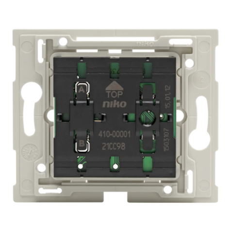
Niko 10-498 User manual

1
10-498
Lees de volledige handleiding vóór installatie en ingebruikname.
1. BESCHRIJVING
De videozender is een inbouwmodule die een videosignaal van een coaxiaal systeem (CVBS)
omzet naar een videosignaal voor Toegangscontrole Standaard.De module staat tevens
toe het videosignaal te versterken of te verzwakken.
systeemaansluiting
voor het regelen
van de versterking
coaxaansluiting camera
voeding camera
De videozender wordt 6-draads bekabeld. Gebruik een getwiste kabel voor een
optimale kwaliteit van het videobeeld. Let daarnaast op de diameter van de aders in
de kabel want deze bepaalt de maximum afstand die behaald kan worden tussen de
voeding en de videozender.
Niko raadt aan om de volgende kabels te gebruiken voor de installatie van de video-
zender:
• JYSTY (-F2) min. 3 x 2 x 0,8mm (max. afstand 200m);
• TVVF (-F2) min. 3 x 2 x 0,8mm (max. afstand 200m);
• TPVF min. 3 x 2 x 0,6mm (max. afstand 100m);
• UTP/FTP/STP 4 x 2 x 0,5mm (max. afstand 70m).
Waarvoor dienen de aan te sluiten draden?
• klemmen a & b: communicatiebus (24VDC)
• klemmen V1 & V2: videosignaal
• klem P & M: extra voeding (26VDC)
Let op! Installeer de videozender niet onder spanning. Sluit het toestel pas na volledige
installatie aan op de netspanning.
NL

2
10-498
2. MONTAGE
Om de camera met de videozender te verbinden moet u de kern van de coaxkabel (75Ω)
voor het videosignaal op klem V (Video IN) aansluiten. De afscherming van de coaxkabel
moet aan de massa ⊥ (Video IN) gehangen worden.
Klem 12V (camera) is een 12V DC-uitgangsklem. Gebruik deze samen met de massa ⊥ om
een externe camera (12V DC; max. 250mA) te voeden. (Zie aansluitschema pag.4)
Voor camera’s waarbij de voeding andere specificaties vertoont, dient u zelf voor een
voeding te zorgen.
3. WERKING EN GEBRUIK
Als de videozender correct aangesloten is, kan h onmiddellk gebruikt worden om het beeld
van een externe camera naar het systeem te sturen. Programmering is niet nodig. U kan
het beeld continu op een monitor of tv laten verschnen met de video-ontvanger (10-499)
of u kan het tdelk oproepen via een videobinnenpost.
In combinate met een audiobuitenpost
Indien de videozender in combinatie met een audiobuitenpost wordt gebruikt, verschnt
het beeld op de videobinnenpost na een oproep aan de buitenpost.
Als extra camera bij een videobuitenpost
Indien u een externe camera wil gebruiken samen met een videobuitenpost, moet u deze met
de videozender aansluiten op een videoswitcher 10-823 (zie handleiding 10-823).
4. TECHNISCHE GEGEVENS
Voedingsspanning:..............+24V DC
Afmetingen (in mm):............H51 x B51 x D22
Gewicht:.............................33g
Bedrfstemperatuur:............-20 tot 50°C
Max. stroomafname: ...........300mA
Uitgang voor camera:..........12V DC; max. 250mA
Ingangsimpedantie:.............75Ω
Uitgangsimpedantie:............100Ω (symmetrisch)
Regelbereik (versterking): ....-3 tot +9dB
Opgelet: gebruik een 75Ω-coaxkabel en 75Ω-connector om een optimale beeldkwaliteit
te garanderen!
NL

3
10-498
5. WETTELIJKE WAARSCHUWINGEN
- De installatie dient te worden uitgevoerd door een erkend installateur en met inachtname
van de geldende voorschriften.
- Deze handleiding dient aan de gebruiker te worden overhandigd. Zij moet bij het dossier
van de elektrische installatie worden gevoegd en dient te worden overgedragen aan
eventuele nieuwe eigenaars. Bijkomende exemplaren zijn verkrijgbaar via de Niko-website
of -supportdienst.
- Bij de installatie dient rekening gehouden te worden met (lijst is niet limitatief):
- de geldende wetten, normen en reglementen;
- de stand van de techniek op het ogenblik van de installatie;
- het feit dat een handleiding alleen algemene bepalingen vermeldt en dient gelezen te
worden binnen het kader van elke specifieke installatie;
- de regels van goed vakmanschap.
- Bij twijfel kan u de supportdienst van Niko raadplegen of contact opnemen met een erkend
controleorganisme.
Support België: Support Nederland:
tel. + 32 3 778 90 80 tel. + 31 183 64 06 60
website: http://www.niko.be website: http://www.niko.nl
In geval van defect kan u uw product terugbezorgen aan een erkende Niko-groothandel
samen met een duidelijke omschrijving van uw klacht (manier van gebruik, vastgestelde
afwijking…).
6. GARANTIEBEPALINGEN
- Garantietermijn: twee jaar vanaf leveringsdatum. Als leveringsdatum geldt de factuurdatum
van aankoop van het goed door de consument. Indien geen factuur voorhanden is, geldt
de productiedatum.
- De consument is verplicht Niko schriftelijk over het gebrek aan overeenstemming te
informeren, uiterlijk binnen de twee maanden na vaststelling.
- In geval van een gebrek aan overeenstemming van het goed heeft de consument recht
op een kosteloze herstelling of vervanging, wat door Niko bepaald wordt.
- Niko is niet verantwoordelijk voor een gebrek of schade als gevolg van een foutieve
installatie, oneigenlijk of onachtzaam gebruik of verkeerde bediening of transformatie
van het goed.
- De dwingende bepalingen van de nationale wetgevingen betreffende de verkoop van
consumptiegoederen en de bescherming van de consumenten van de landen waarin
Niko rechtstreeks of via zuster/dochtervennootschappen, filialen, distributeurs, agenten
of vaste vertegenwoordigers verkoopt, hebben voorrang op bovenstaande bepalingen.
NL

4
10-498
7. AANSLUITSCHEMA
NL
10-589
230V~
a b E P M
a b P M
V1 V2
V1 V2
19 20
L N
a b P
10-806
10-498
V1 V2
21 22
8VAC
a b RP

5
10-498
Lisez entièrement le mode d’emploi avant toute installation et mise en service.
1. DESCRIPTION
L’ émetteur vidéo est un module à encastrer qui transforme un signal vidéo pour un système
coaxial en un signal vidéo Contrôle d’accès standard. Le module permet également de
renforcer ou d’affaiblir le signal vidéo.
Raccordement du système
Pour régler l’amplication
Prise coaxiale de la caméra
Alimentation de la caméra
L’émetteur vidéo est câblé à 6 fils. Utilisez un câble torsadé pour une qualité d’image
vidéo optimale.
Tenez compte en outre du diamètre des conducteurs dans le câble, celui-ci déterminant la
distance maximale pouvant être couverte entre l’alimentation et l’émetteur vidéo.
Niko conseille l’utilisation des câbles suivants pour l’installation du émetteur vidéo:
• JYSTY(-F2) min. 3 x 2 x 0,8 mm (distance max. 200 m);
• TVVF (-F2) min. 3 x 2 x 0,8 mm (distance max. 200 m);
• TPVF min. 3 x 2 x 0,6 mm (distance max. 100 m);
• UTP/FTP/STP 4 x 2 x 0,5 mm (distance max. 70 m).
A quoi servent les fils à raccorder?
• bornes a & b: bus de communication (24V DC)
• bornes V1 & V2: signal vidéo
• borne P & M: alimentation supplémentaire (26VDC)
Attention! N’installez pas l’émetteur vidéo sous tension. Ne raccordez l’appareil à la
tension réseau qu’après installation complète.
FR

6
10-498
2. MONTAGE
Pour raccorder la caméra à l’émetteur vidéo, vous devez raccorder le centre du câble coaxial
(75Ω) pour le signal vidéo à la borne V (vidéo IN). Le blindage du câble coaxial doit être
raccordé à la masse ⊥ (Video IN).
La borne 12V (camera) est une borne de sortie 12V DC. Utilisez cette borne avec la masse
⊥ pour diriger une caméra externe (12V DC, max. 250mA). (Voir schéma de raccordement
page 8)
Si votre caméra exige d’autres caractéristiques quant à l’alimentation, vous devez vous-
même prévoir l’alimentation.
3. FONCTIONNEMENT ET UTILISATION
Lorsque l’émetteur vidéo est correctement raccordé, il peut être utilisé immédiatement pour
transmettre l’image d’une caméra externe vers un système. Aucune programmation n’est
nécessaire. Vous pouvez faire apparaître l’image de manière continue sur le moniteur ou
sur le téléviseur via le récepteur vidéo (10-499), ou vous pouvez appeler temporairement
l’image via un poste intérieur vidéo.
En combinaison avec un poste extérieur audio
Si l’émetteur vidéo est utilisé en combinaison avec un poste extérieur audio, l’image du
poste intérieur vidéo est afchée après un appel au poste extérieur.
Comme caméra supplémentaire pour un poste extérieur vidéo
Si vous souhaitez utiliser une caméra externe avec un poste extérieur vidéo, vous devez
raccorder ce dernier avec l’émetteur vidéo sur un sélecteur vidéo 10-823 (voir manuel
du 10-823).
4. CARACTERISTIQUES TECHNIQUES
Tension d’alimentation:.........................+24V DC)
Dimensions (en mm): ...........................H51 x l51 x P22
Poids:..................................................33g
Température de service:.......................de -20°C à 50°C
Consommation max. de courant:...........300mA
Sortie pour caméra:..............................12V DC; max. 250mA
Impédance d’entrée: ............................75Ω
Impédance de sortie:............................100Ω (symétrique)
Plage de réglage (amplication): ...........-3 à +9dB
Attention: l’émetteur doit être raccordé à un câble coaxial 75Ω et à un connecteur 75Ω,
an de garantir une qualité d’image optimale!
FR

7
10-498
5. PRESCRIPTIONS LEGALES
- L’installation doit être effectuée par un installateur agréé et dans le respect des prescriptions
en vigueur.
- Ce mode d’emploi doit être remis à l’utilisateur. Il doit être joint au dossier de l’installation
électrique et être remis à d’éventuels autres propriétaires.Des exemplaires supplémentaires
peuvent être obtenus sur le site web ou auprès du service ‘support Niko’.
- Il y a lieu de tenir compte des points suivants avant l’installation (liste non limitative):
- les lois, normes et réglementations en vigueur;
- l’état de la technique au moment de l’installation;
- ce mode d’emploi qui doit être lu dans le cadre de toute installation spécifique;
- les règles de l’art.
- En cas de doute, vous pouvez appeler le service ‘support Niko’ ou vous adresser à un
organisme de contrôle reconnu.
Support Belgique: Support France:
+ 32 3 778 90 80 + 33 820 20 6625
site web: http://www.niko.be site web: http://www.niko.fr
En cas de défaut de votre appareil, vous pouvez le retourner à un grossiste Niko agréé,
accompagné d’une description détaillée de votre plainte (manière d’utilisation, divergence
constatée…).
6. CONDITIONS DE GARANTIE
- Délai de garantie: 2 ans à partir de la date de livraison. La date de la facture d’achat
par le consommateur fait office de date de livraison. Sans facture disponible, la date de
fabrication est seule valable.
- Le consommateur est tenu de prévenir Niko par écrit de tout manquement à la concordance
des produits dans un délai max. de 2 mois après constatation.
- Au cas ou pareil manquement serait constaté, le consommateur a droit à une réparation
gratuite ou à un remplacement gratuit selon l’avis de Niko.
- Niko ne peut être tenu pour responsable pour un défaut ou des dégâts suite à une installation
fautive, à une utilisation contraire ou inadaptée ou à une transformation du produit.
- Les dispositions contraignantes des législations nationales ayant trait à la vente de
biens de consommation et la protection des consommateurs des différents pays où Niko
procède à la vente directe ou par entreprises interposées, filiales, distributeurs, agents
ou représentants fixes, prévalent sur les dispositions susmentionnées.
FR

8
10-498
FR
7. SCHEMA DE RACCORDEMENT
10-589
230V~
a b E P M
a b P M
V1 V2
V1 V2
19 20
L N
a b P
10-806
10-498
V1 V2
21 22
8VAC
a b RP

9
10-498
Bitte lesen Sie die Anleitung vor der Installation vollständig durch.
1. BESCHREIBUNG
Der Videosender ist ein unter Putz verlegtes Modul, das ein Videosignal von einem Koaxi-
al-System (CVBS) in ein Videosignal für den Zugangskontrolle – Standard konvertiert.
Dieses Videosignal erlaubt außerdem die Verstärkung oder Dämpfung des Videosignals.
Systemanschluss
Zur Regelung der Verstärkung
Koaxialanschluss Kamera
Stromversorgung Kamera
Die Videosender wird 6-polig verkabelt. Verwenden Sie ein verdrilltes Kabel, um eine
optimale Qualität des Videobilds zu erzielen.
Achten Sie außerdem auf den Durchmesser der Kabeladern, denn dieser bestimmt den
Maximalabstand zwischen Netzteil und Videosender.
Niko empfiehlt, für die Installation der Videosender folgende Kabel zu verwenden:
• JYSTY (-F2) min. 3 x 2 x 0,8mm (max. Abstand 200m);
• TVVF (-F2) min. 3 x 2 x 0,8mm (max. Abstand 200m);
• TPVF min. 3 x 2 x 0,6mm (max. Abstand 100m);
• UTP/FTP/STP 4 x 2 x 0,5mm (max. Abstand 70m).
Wofür dienen die anzuschließenden Drähte?
• Klemmen a & b: Kommunikationsbus (24VDC)
• Klemmen V1 & V2: Videosignal
• Klemme P & M: zusätzliches Netzteil (26VDC)
Achtung! Installieren Sie die Videosender nur, wenn diese nicht unter Spannung steht.
Schließen Sie das Gerät erst nach vollständiger Installation an die Netzspannung an.
DE

10
10-498
2. MONTAGE
Sie verbinden die Kamera mit dem Sender, indem Sie den Kern eines Koaxial-Kabels (75Ω)
für das Videosignal mit dem Anschluss V (Video IN) verbinden. Verbinden Sie den Schutzleiter
des Koaxial-Kabels mit dem Schutzleiter ⊥ des Anschlusses (Video IN).
Der Anschluss 12V (Kamera) ist ein 12-Volt-Gleichstromausgang. Benutzen Sie diesen
Anschluss zusammen mit dem Erdungsanschluss ⊥, um die externe Kamera zu steuern
(12 V Gleichstrom; max. 250 mA). (Siehe Anschlussplan S.12)
Bei Kameras mit einer anderen Art der Stromversorgung muss der Endanwender für die
Stromquelle sorgen.
3. BETRIEB UND EINSATZ
Wenn der Videosender richtig angeschlossen ist, kann er sofort eingesetzt werden, um das
Bild einer externen Kamera an das System zu sind. Das Bild kann mit dem Videoempfänger
(10-499) dauerhaft auf einem Monitor oder TV-Gerät angezeigt werden oder zwischenzeitlich
mit einer internen Videoeinheit.
In Verbindung mit einer externen Audioeinheit
Wenn der Videosender zusammen mit einer externen Audioeinheit genutzt wird, was das
Bild auf der internen Videoeinheit angezeigt, wenn die externe Einheit aktiv wird.
Als Extrakamera mit einer externen Videoeinheit
Wenn eine externe Kamera zusammen mit einer externen Videoeinheit genutzt wird, müssen
sie beide mit dem Videoumschalter 10-823 (siehe Handbuch 10-823) eingesetzt werden.
4. TECHNISCHE DATEN
Spannung der Stromversorgung:........... + 24 V Gleichstrom
Abmessungen (in mm):.........................H 51 x B 51 x T 22
Gewicht:..............................................33 g
Betriebstemperatur: .............................- 20° C bis +50° C
Maximaler Energieverbrauch:................300 mA
Kameraausgang:..................................12V Gleichstrom; max. 250 mA
Eingangswiderstand:............................75Ω
Ausgangswiderstand:...........................100Ω (symmetrisch)
Anpassungsbereich (Verstärkung): ........-3 bis +9dB
Achtung: Benutzen Sie ein Koaxialkabel und einen Verbinder mit 75Ω, um eine optimale
Bildqualität zu garantieren!
DE

11
10-498
5. GESETZLICHE BESTIMMUNGEN
- Die Installation darf ausschließlich von einem Fachmann des Elektrohandwerks unter
Berücksichtigung der geltenden Vorschriften vorgenommen werden.
- Übergeben Sie dem Benutzer diese Gebrauchsanleitung. Sie ist den Unterlagen der elektri-
schen Anlage beizufügen und muss auch eventuellen neuen Besitzern übergeben werden.
Zusätzliche Exemplare erhalten Sie über unsere Website oder unseren Servicedienst.
- Bei der Installation müssen Sie u.a. Folgendes berücksichtigen:
- die geltenden Gesetze, Normen und Vorschriften;
- den Stand der Technik zum Zeitpunkt der Installation;
- diese Gebrauchsanleitung die im Zusammenhang mit jeder spezifischen Anlage gesehen
werden muss;
- die Regeln fachmännischen Könnens.
- Sollten Sie Fragen haben, können Sie sich an die Niko-Hotline oder an eine anerkannte
Kontrollstelle wenden:
Hotline Belgien: +32 3 778 90 80
Im Falle eines Defektes an Ihrem Niko-Produkt, können Sie dieses mit einer genauen
Fehlerbeschreibung (Anwendungsproblem, festgestellter Fehler, usw.) an Niko-EGH
zurückbringen.
6. GARANTIEBESTIMMUNGEN
- Garantiezeitraum: Zwei Jahre ab Lieferdatum. Als Lieferdatum gilt das Rechnungsdatum
zu dem der Endkunde das Produkt gekauft hat. Falls keine Rechnung mehr vorhanden
ist, gilt das Produktionsdatum.
- Der Endkunde ist verpflichtet, Niko über den festgestellten Mangel innerhalb von zwei
Monaten zu informieren.
- Im Falle eines Mangels an dem Produkt hat der Endkunde das Recht auf eine kostenlose
Reparatur oder Ersatz. Dies wird von Niko entschieden.
- Niko ist nicht für einen Mangel oder Schaden verantwortlich, der durch unsachgemäße
Installation, nicht bestimmungsgemäßen oder unvorsichtigen Gebrauch oder falsche Bedienung
oder Anpassen/Ändern des Produktes entsteht.
- Die zwingenden Vorschriften der nationalen Gesetzgebung bezüglich des Verkaufs von
Konsumgütern und der Schutz des Kunden in den Ländern in denen Niko direkt oder über
seine Tochtergesellschaften, Filialen, Distributoren, Handelsvertretungen oder Vertretern
verkauft, haben Vorrang vor den obigen Bestimmungen.
DE

12
10-498
DE
7. ANSCHLUSSPLAN
10-589
230V~
a b E P M
a b P M
V1 V2
V1 V2
19 20
L N
a b P
10-806
10-498
V1 V2
21 22
8VAC
a b RP

13
10-498
Read the complete manual before attempting installation and activating the
system.
1. DESCRIPTION
The video transmitter is a ush mounting module that converts a video signal from a coaxial
system into a Niko Access Control video signal. The module also allows the video signal
to be amplied or attenuated.
System connection
For gain control
Camera coax connection
Camera power supply
The video transmitter has to be cabled in a 6-wire way. Use a twisted cable for an
optimum image quality. Pay attention to the diameter of the wires in the cable, as this
determines the maximum distance that can be covered between the power supply and
the video transmitter.
Niko recommends using the following cables:
• JYSTY(-F2) min. 3 x 2 x 0.8mm (max. distance 200m);
• TVVF (-F2) min. 3 x 2 x 0.8mm (max. distance 200m);
• TPVF min. 3 x 2 x 0.6mm (max. distance 100m);
• UTP/FTP/STP 4 x 2 x 0.5mm (max. distance 70m).
Function of the wires to be connected:
• terminals a & b: communication bus (24 VDC)
• terminals V1 & V2: video signal
• terminal P & M (b): extra power supply (26 VDC)
Note! Disconnect all power before installing the video transmitter. Do not connect
the unit to the power supply until installation is complete
EN

14
10-498
2. MOUNTING
To connect the camera to the video transmitter, connect the core of the coax cable (75Ω)
for the video signal to terminal V (Video IN). The shield of the coaxial cable must be con-
nected to the mass ⊥ (Video IN).
Terminal 12V (camera) is a 12V DC output terminal. Use this terminal in combination with
the mass ⊥ in order to control an external camera (12V DC; max. 250mA). (See connec-
tion diagram p.16)
For cameras with a power supply with other specications, you must provide the power
supply yourself.
3. OPERATION AND USE
If the video transmitter has been connected correctly, it can immediately be used to send
the image of an external camera to the system. No need for programming. The image can
be displayed continuously on a monitor or TV via the video receiver (10-499) or temporarily
via a internal video unit.
In combination with an external audio unit
If the video transmitter is used in combination with an external audio unit, the image is
displayed on the video internal unit after a call at the external unit.
As extra camera for a video external unit
If you want to use an external camera in combination with a video external unit, you must
connect it with the video transmitter to a video switcher 10-823 (see manual 10-823).
4. TECHNICAL DATA
Power supply voltage:.................. +24V DC
Dimensions (in mm): ................... H51 x W51 x D22
Weight:....................................... 33g
Operating temperature: ............... -20 to 50°C
Max. power consumption:............ 300mA
Camera output:........................... 12V DC; max. 250mA
Input impedance: ........................ 75Ω
Output impedance:...................... 100Ω (symmetrical)
Adjusting range (amplication:..... -3 to +9dB
Attention: Use a 75Ω coaxial cable and 75Ω connector in order to guarantee an optimum
image quality!
EN

15
10-498
5. LEGAL WARNINGS
- The installation has to be carried out by a registered installer and in compliance with the
statutory regulations.
- This user manual has to be handed over to the user. It has to be included in the electrical
installation file and has to be passed on to any new owners. Additional copies are available
on the Niko website or via the support service.
- During installation, the following has to be taken into account (not limited to list below):
- The statutory laws, standards and regulations;
- The state of the art technique at the moment of installation;
- This user manual, which must be read within the scope of each specific installation, only
states general regulations;
- The rules of proper workmanship
- In case of questions, you can consult Niko’s support service or contact a registered control
organisation.
Support Belgium: Support UK:
+32 3 778 90 80 +44 1525877707
website : http://www.niko.be website: http://www.nikouk.com
In case of a defect, you can return your product to a registered Niko wholesaler, together
with a clear description of your complaint (Conditions of use, stated defect…).
6. GUARANTEE PROVISIONS
- Period of guarantee: 2 years from date of delivery. The delivery date is the invoice date
of purchase of the product by the consumer. If there is no invoice, the date of production
applies.
- The consumer is obliged to inform Niko in writing about the defect, within two months
after stating the defect.
- In case of a failure to conform, the consumer has the right to a repair or replacement
(decided by Niko) free of charge.
- Niko cannot be held liable for a defect or damage as a result of an incorrect installation,
improper or careless use or wrong usage or transformation of the goods.
- The compulsory regulations of the national legislation concerning the sales of consumer
goods and the protection of the consumers in the countries where Niko sells, directly or
via sister or daughter companies, chain stores, distributors, agents or permanent sales
representatives, take priority over the rules and regulations mentioned above.
EN

16
10-498
7. WIRING DIAGRAM
EN
10-589
230V~
a b E P M
a b P M
V1 V2
V1 V2
19 20
L N
a b P
10-806
10-498
V1 V2
21 22
8VAC
a b RP

17
10-498
Lea la totalidad del manual antes de proceder a su instalación.
1. DESCRIPCIÓN
El transmisor de vídeo es un módulo de montaje empotrado que convierte la señal de vídeo
procedente de un sistema coaxial (CVBS) en señal de vídeo de la gama Access Control
Standard. El módulo también permite amplicar o atenuar la señal de vídeo.
Conexión del sistema
Para control de ganancia
Conexión coaxial de la cámara
Alimentación eléctrica de la cámara
La transmisor de vídeo utiliza un cableado de 6 hilos. Utilice un cable trenzado para
garantizar una calidad óptima de las imágenes de vídeo.
Preste atención al diámetro de los conductores del cable, ya que el diámetro determina la distancia
máxima a la que es posible conectar la fuente de alimentación y la transmisor de vídeo.
Niko recomienda usar los cables siguientes al instalar la transmisor de vídeo:
• JYSTY (-F2) mín. 3 x 2 x 0,8 mm (distancia máx. 200 m);
• TVVF (-F2) mín. 3 x 2 x 0,8 mm (distancia máx. 200 m);
• TPVF mín. 3 x 2 x 0,6 mm (distancia máx. 100 m);
• UTP/FTP/STP 4 x 2 x 0,5 mm (distancia máx. 70 m).
Función de los cables de conexión:
• Terminales a y b: bus de comunicación (24 VCC)
• Terminales V1 y V2: señal de vídeo
• Terminales P & M: fuente de alimentación adicional (26VDC)
Nota! Asegúrese de que la transmisor de vídeo no esté conectada a ninguna fuente
de alimentación antes de instalarla. No conecte la unidad a la fuente de alimentación
hasta finalizar la instalación.
SP

18
10-498
2. MONTAJE
Para conectar la cámara al transmisor de vídeo, conecte el núcleo del cable coaxial (75_)
de la señal de vídeo entrante al terminal V (Vídeo IN). Conecte el apantallamiento del cable
coaxial al terminal de puesta a tierra ⊥ (Video IN).
El terminal 12V (cámara) es un terminal de salida de 12 V CC. Utilice este terminal, junto
con el terminal de puesta a tierra ⊥, para controlar una cámara externa (12 V CC, máx.
250 mA). (Ver el diagrama de conexión de la p. 20)
Si la cámara tiene especificada una alimentación diferente, el usuario deberá proporci-
onarla.
3. FUNCIONAMIENTO Y UTILIZACIÓN
Si el transmisor de vídeo se ha conectado correctamente, podrá utilizarse de inmediato
para enviar al sistema la imagen de una cámara externa. La imagen podrá reproducirse de
forma continua en un monitor o en un televisor, a través del receptor de vídeo (10-499), o
momentáneamente a través de una unidad interna de vídeo.
En combinación con una unidad externa de audio
Si el transmisor de vídeo se utiliza en combinación con una unidad externa de audio, la
imagen aparecerá en la unidad interna de vídeo cuando se haga una llamada desde la
unidad externa. Consulte el diagrama de conexión.
Con una cámara adicional y una unidad externa de vídeo
Si se va a utilizar una cámara externa en combinación con una unidad externa de vídeo,
deberán conectarse las dos a un sistema de conmutación de vídeo 10-823 (véase el
manual 10-823).
4. DATOS TÉCNICOS
Tensión de alimentación: ......................+24 V CC
Dimensiones (mm): ..............................51 (altura) x 51 (anchura) x 22 (profundidad)
Peso:...................................................33 g
Temperatura de funcionamiento:...........-20 a 50 °C
Consumo máx. de potencia:..................300 mA
Salida de la cámara:.............................12V CC; máx. 250 mA
Impedancia de entrada:........................75Ω
Impedancia de salida:...........................100Ω (simétrica)
Intervalo de ajuste (amplicación):.........-3 a +9dB
Atención: Para garantizar una calidad de imagen óptima, utilice cable coaxial de 75Ω y
un conector de 75Ω.
SP

19
10-498
5. PRESCRIPCIONES LEGALES
- La instalación debe ser realizada por una instalador credenciado, con arreglo a la normativa
en vigor.
- Estas instrucciones deben entregarse al usuario. Deben adjuntarse al expediente de la
instalación eléctrica, y transmitirse a cualquier eventual nuevo propietario. Se pueden
obtener ejemplares adicionales en el sitio web o en el servicio de asistencia de Niko.
- Antes de proceder a la instalación, se debe tener en cuenta lo siguiente (lista no exhaus-
tiva):
- las leyes, normas y reglamentos en vigor;
- el progreso tecnológico en el momento de la instalación;
- las presentes instrucciones, que deben leerse antes de proceder a cualquier instalación
específica;
- las prácticas del sector.
- En caso de duda, puede ponerse en contacto con el servicio de asistencia de post-venta
Niko o dirigirse a un organismo de control reconocido.
Asistencia en Bélgica:
+ 32 3 778 90 80
sitio web: http://www.niko.be
En el caso de un defecto de su producto, puede devolverlo a un distribuidor de Niko,
acompañado de una descripción detallada de su queja (modo de utilización, defecto
constatado, etc.).
6. CONDICIONES DE GARANTÍA
- Validez de la garantía: 2 años a partir de la fecha de entrega. La fecha de la factura de
compra por el usuario sirve de fecha de entrega. Sin factura disponible, la validez de la
garantía será de 2 años a partir de la fecha de fabricación.
- El usuario deberá comunicar a Niko por escrito cualquier disconformidad en los productos
en un plazo máximo de 2 meses a partir del momento en que la detecte.
- En caso de que la disconformidad se constate, el usuario se benecia de una reparación
gratuita o sustitución gratuita, según criterio de Niko.
- Niko declina toda responsabilidad por defectos o daños derivados de una instalación incor-
recta, de una utilización contraria o inadecuada, o de una transformación del producto.
- Las disposiciones vigentes de las legislaciones nacionales que afectan a la venta de
bienes consumo y a la protección de los consumidores de los distintos países donde Niko
procede a la venta directa o mediante empresas intermediarias, liales, distribuidores o
representantes jos, prevalecen sobre las disposiciones anteriores.
SP

20
10-498
7. DIAGRAMA DE CABLEADO
SP
10-589
230V~
a b E P M
a b P M
V1 V2
V1 V2
19 20
L N
a b P
10-806
10-498
V1 V2
21 22
8VAC
a b RP
Table of contents
Languages:
Other Niko Transmitter manuals