KJB XtremeLife WIRELESS PIR QUAD User manual

PIR QUAD / QUAD LCD
Receiver Information 2
Initial Setup 4
Remote Control 7
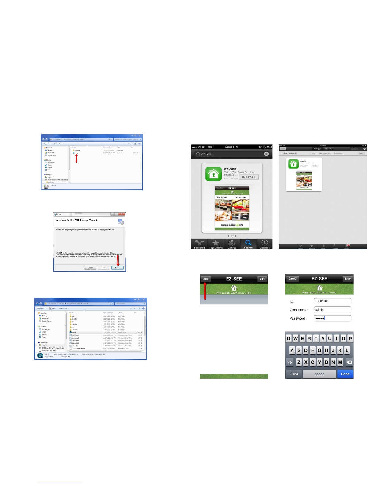
ASP4 Software / Computer Recording 8
Remote View 11
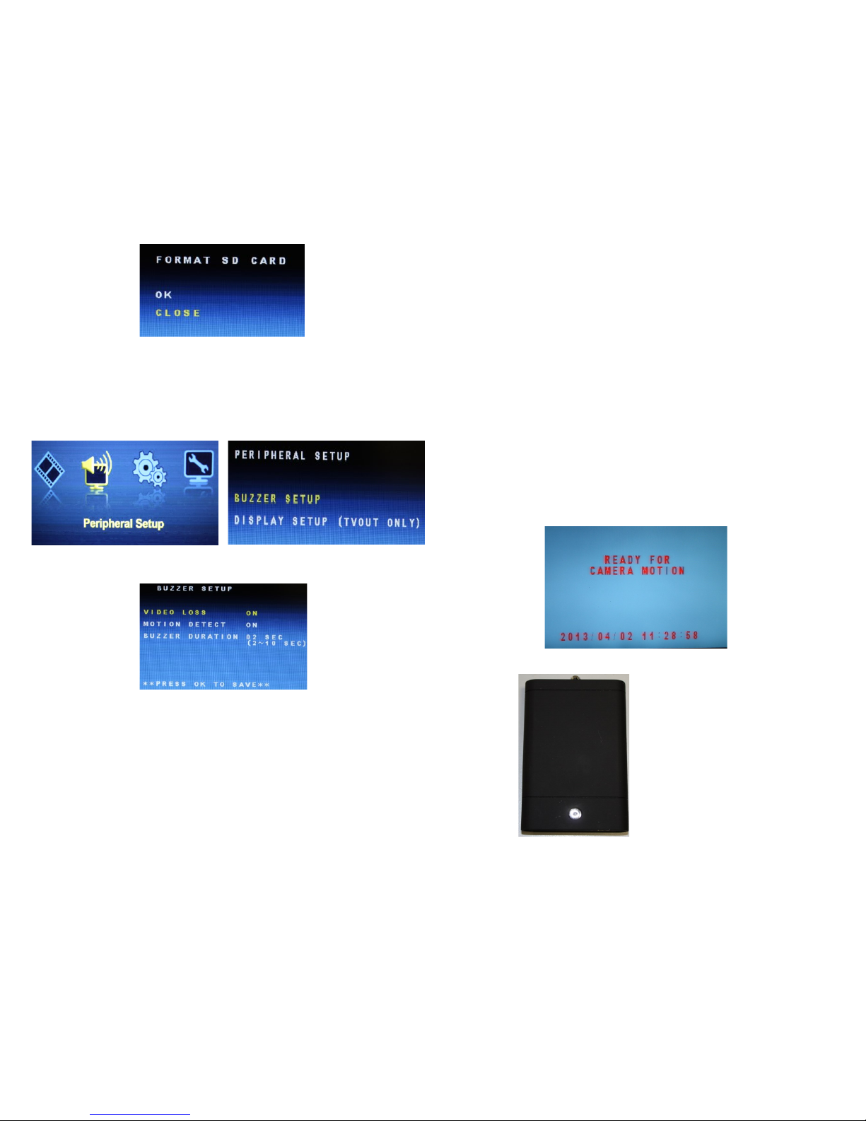
Receiver Menu / SD Recording 15
Table of Contents
1
20
Manufacturer’s Limited Warranty
Manufacturer warrants all Covert Video and Sleuth Gear Hidden Video Products (Product) assembled and
sold by Manufacturer to be free of defects in material and workmanship, subject to the following conditions. The
duration of Manufacturer's warranty with respect to the Product is limited to one (1) year from the date of sale to
the original consumer purchaser only for Products delivered within the fifty (50) states of the United States, Dis-
trict of Columbia, or the possessions and territories of the United States
No other express warranties are made with respect to any Product. All implied warranties, including
warranties of merchantability and fitness for a particular purpose are limited to the warranty period set
forth above. This warranty is not transferable and applies only to the original consumer purchaser of the
Product.
Manufacturer will, as its sole obligation under this warranty, replace or repair, at its option, any Product
that does not conform to this warranty. Under no circumstances will the Manufacturer issue credit or give a re-
fund for Product covered by this warranty. Furthermore, under no circumstances will Manufacturer be liable for
any incidental or consequential damages under this warranty or any implied warranties.
What Is Not Covered. This limited warr anty does not cover Products that in Manufactur er’s judg-
ment have damage resulting from any (i) deviation from Manufacturer's operating instructions as printed in Man-
ufacturer's catalog or on any packaging, labels or other literature provided with a Product, (ii) installation of a
Product in a manner which is inconsistent with Manufacturer's written instructions, (iii) alteration, modification
of or tempering with a Product, (iv) misuse, (v) neglect, (vi) abuse, (vii) accident, (viii) power surge, static elec-
tricity or other electrical discharge, (ix) normal wear and tear, (x) commercial use, (xi) service by anyone other
than a Manufacturer authorized repair facility, or (xii) other improper application, installation or operation of the
Product. Or, (xiii) have been purchased from inventory clearance or liquidation sales or other sales in which
Manufacturer expressly disclaims its warranty obligation pertaining to the Product.
How you (the Customer) can get service: To obtain warranty service during the warranty period, you
must return the defective Product with the original receipt to the original place of purchase. Contact them for
return instructions.
If warranty service is needed at any time during the warranty period, the purchaser will be required to
furnish a sales receipt/proof of purchase indicating the date of purchase, amount paid and place of purchase.
Customers who fail to provide such proof of purchase will be charged for the repair of any Product.
How state law relates to the warranty: Some states do not allow limitations on how long implied war-
ranties last, or the exclusion or the limitation of incidental or consequential damages. So the above limitations or
exclusions may not apply to you. This warranty gives you specific legal rights. You may also have other rights
that may vary from state to state.
NO PERSON IS AUTHORIZED BY MANUFACTURER TO MODIFY OR ADD TO THIS LIM-
ITED WARRANTY.
For warranty information on Products delivered outside the United States please contact the original place of
purchase.
IT IS THE USER’S RESPONSIBILITY TO ENSURE THAT THIS EQUIPMENT IS USED IN ACCORD-
ANCE WITH THE LAW(S) OF THE JURISDICTION IN WHICH THIS EQUIPMENT IS UTILIZED.
DO NOT ATTEMPT TO RETURN PRODUCT TO ORIGINAL MANUFACTURER, AS THIS PRODUCT
HAS BEEN MODIFIED AND IS NO LONGER SUBJECT TO ORIGINAL MANUFACTURER’S WARRAN-
TY. IN THE CASE OF A DEFECTIVE PRODUCT, CONTACT PLACE OF PURCHASE FOR RETURN
PROCEDURE.
THIS EQUIPMENT HAS BEEN TESTED AND HAS BEEN FOUND TO BE IN COMPLIANCE WITH THE
LIMITS FOR A CLASS B DIGITAL DEVICE, PURSUANT TO PART 15 OF THE FCC RULES. THESE
LIMITS ARE DESIGNED TO PROVIDE REASONABLE PROTECTIONS AGAINST HARMFUL INTER-
FERENCE IN A RESIDENTIAL INSTALLATION. THIS EQUIPMENT USES, GENERATES AND CAN
RADIATE RADIO FREQUENCY ENERGY AND IF NOT INSTALLED AND USED IN ACCORDANCE
WITH INSTRUCTIONS, MAY CAUSE HARMFUL INTERFERENCE TO RADIO COMMUNICATIONS.
Part 15 Low Power:
ANY CHANGES OR MODIFICATIONS TO THIS EQUIPMENT WITHOUT THE EXPRESS AUTHORIZA-
TION OF THE MANUFACTURER COULD VOID THE USER’S AUTHORITY TO OPERATE THIS EQUIP-
MENT. (RULE 15.21 OF THE FCC)
XtremeLife WIRELESS
iPad/iPhone Android App 12

Receiver Information
Quad Version
1. Receiver
2. RCA Cables
3. USB Cable
4. Antenna
5. Remote
6. Power Supply
Quad LCD Version
1. Receiver
2. Remote
3. RCA Cables
4. Receiver Brackets
5. USB Cable
6. Antenna
7. Power Supply
1
2
3
456
1
23
4
5
6
7
2
Video Playback
Press the PLAY button on the remote to enter to the video playback section.
Playback List - shows the dates of the recorded video given by the date and
time stamp. Scroll to the playback date you would like to view and press OK
on the remote.
The next list will show the time stamp of when the recording started and end-
ed. Scroll to the time you would like to view and press OK on the remote.
During video play back press the up or down arrow to move to the next video.
19

Quad Receiver
Quad LCD Receiver
3
18
Factory Default
Factory Default - is to restore back to defaults as come from the manufactur-
er. This is a good troubleshooting step regarding any type of issue with the
receiver.
Brightness Setup
Brightness Setup - change the level to increase or decrease the brightness of
the image.

Initial Setup
Pairing Camera and Receiver
1. Press the Power Button on your receiver. The Power LED will glow red when
power is on.
1.2. If using the Quad receiver connect the provided RCA cables from the video
output on the receiver to the input on a TV or monitor
2. Connect the power supply to your camera.
3. How to pair:
3.1. Select a channel on the receiver by pressing the pair button. Press and hold the
pair button until the channel LED flashes blue.
3.2. Press the pair button on your camera. (See pair button location on pg 5)
3.3. If the pairing is successful the blue channel LED on the receiver will flash
rapidly and the camera image will be shown on the monitor or TV.
4. To pair additional cameras press pair button and release quickly to change
receiver channel. Then repeat pairing process on new channel.
4
System Setup
Date / Time Setup
Date / Time Setup - is to set the date and time stamp on the video recording.
Time Format - is to change from a 12 hour to 24 hour format.
Set the current time and press OK to save.
Sequence Time
Sequence Time - is to change the amount of time the channel will show on
the screen before switching to the next channel. To place the monitor in se-
quence mode press the SEQUENCE button on the remote.
17

16
Format SD Card
Format SD Card - will erase all data that is currently on the card. This will
also put a new SD card in the correct format for the receiver to record.
Peripheral Setup
Buzzer Setup
Buzzer Setup - is a beeping noise the receiver makes when an event takes
place.
Video Loss - If there is a loss in connection with the camera and receiver the
buzzer will sound.
Motion Detect - If motion is detected the buzzer will sound.
Buzzer Duration - Is the amount of time the buzzer will sound.
PIR Camera Setup
PIR sensors detect levels of infrared radiation. The hotter an object is the more
radiation it emits. When there is a change in radiation levels this is considered
motion, the transmitter will turn on and connect with the receiver. The PIR sensor
does not need very much power to detect radiation so the transmitter’s power will
be off even though the PIR sensor is still detecting radiation. When the PIR de-
tects a change in radiation the transmitter will turn on and automatically pair with
the receiver. In order for the transmitter to automatically pair with the receiver
they will first need to be manually paired. See pg. 4 (Initial Setup) for pairing in-
structions.
When the PIR sensor detects a change in heat the cameras image will be shown
on the monitor. When the PIR sensor does not recognize a change in heat the
sensor will trigger the transmitter to turn off. While the transmitter is turned off
the cameras image will go blank and the image below will appear. This image will
only appear on the LCD receiver or when the non-LCD receiver is connected to a
monitor. When using ASP4 software the cameras image will freeze. When the PIR
detects heat and triggers the transmitter the image will resume to the image.
5
Battery Pack LED Status
Charging: RED
Fully Charged: BLUE
On: BLUE
Off/Dead Battery: OFF
To charge the battery pack
connect to USB power using
the provided USB cable.

15
Receiver Menu
Recording Setup - For SD Recording Only
Schedule Setup
Schedule setup - allows to cr eate a customized 7 day recording schedule.
Each digit allocates 1 hour of time.
PANIC - is for manual recording. When in PANIC press the RECORD but-
ton on the remote to start manual recording.
MOTION - is for motion detection recording. When in MOTION the unit will
only record when motion is present.
CONTINOUS - is for continuous recording. When in CONTINUOUS the
unit will constantly record.
SD Information
Total - shows the amount of space the SD card can hold. If the SD card is
inserted in the receiver and the total shows 0.0 GB the receiver does not
recognize the SD card and will need to be formatted. (see Format SD pg 15)
Remain - shows the amount of space left on the SD card.
Full stop - means to stop recording with the SD card is full.
Overwrite - means to recycle the oldest file when the SD card is full to keep
recording.
AFTER RECORDING SETUP IS
COMPLETE PRESS THE
RECORD
BUTTON ON THE REMOTE TO
INITIATE RECORDING.
6
Pair Button
Smoke Detector
Wall Clock
Pair Button Location
Teddy Bear
Landscape Stone

Select the receiver ID.
Watch live stream video.
14 7
Remote Control
iPad/iPhone/Android App

iPad/iPhone App
After the download is complete, open the app and select “Add” in the top left
corner. Enter your receiver ID, user name, and password.
13
8
ASP4 Installation Instructions
1. Insert ASP4 CD into your computer.
2. Double click on the setup icon to start the installation wizard.
3. Click next to run through the installation wizard.
4. To create a shortcut to the software on your desktop find the installation loca-
tion of the software. Right click ASP4 and go to send to and select Desktop.
Open the App Store or go to Google Play and search for “EZ-See” to
download the app.

Remote View Minimum Requirements
To use the remote viewing on PC, we highly recommend you to have the
following software and hardware specifications on your PC:
Microsoft Windows XP or Windows 7 (.NET Framework 3.5 higher)
Internet Explorer 8 or higher.
Google Chrome
CPU: 2.0GHz or higher(only support x86 and x64)
Memory: 1GB
Display card: Independent display card and support DirectX 9.0 or
higher.
To use the remote viewing on iPhone/iPad, we highly recommend you to
have the following software and hardware and your iPhone/iPad:
iPhone 3 or higher
iPad
iOS 4.3 or higher
Recommended internet speed: 1 MB per second upload speed.
The download speed is irrelevant for the network where the receiver is
located as the video stream is uploaded to the EZ-See server. To check your
internet speed go to http://www.speedtest.net/.
In order to enable constant remote video access a PC will need to be
on at all times running the supplied ASP4 software. The receiver will
also need to be connected to the USB port of the same PC that is run-
ning the ASP4 software.
A Few Words About Remote-View Technology
Streaming video is only as good as the equipment and connections that
enable it. There are many variables that affect how smooth the video stream
is that you actually see remotely. These variables include the speed, current
load, and bandwidth of the internet connections of both the web server
(your computer) and the remote view computer or smart phone, your ISP's
limitations on bandwidth, the speed and current load on your cellular net-
work (2G, 3G, 4G, etc). Video loss and freezing video are typically due to
an insufficient internet connection. If video loss or freezing occurs this will
not affect ASP4 recording.
12 9
ASP4 User Interface

Remote View
1. Enter the remote view address in to the address bar as shown below.
2. Enter the user name and password if changed from default user name/password.
3. If user name and password are correct, ASP4 software will launch and the web
service icon is on the image will appear.
11
ASP4 Settings
After installation open the software and click the settings button.
“Snapshot” and “Video” will show the storage location of the recorded data.
Via “Network Settings” users can change the user name and password. The
user name and password has a 12 digit capacity.
“Got to remote view at:” shows the website that is specific to this receiver.
Use Internet Explorer or Google Chrome to log in and access the video live
stream by typing in the link to the address bar of the web browser.
Click “OK” to save the settings after they have been changed.
10
This manual suits for next models
1
Table of contents
Other KJB Camcorder manuals