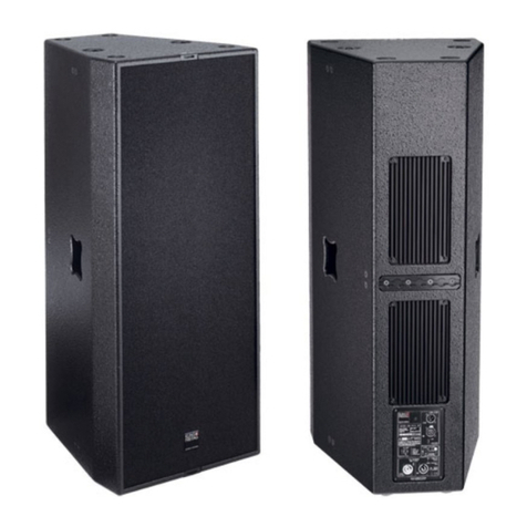
User's Manual K&F SPECTRA 212 Rigging System
KLING & FREITAG GMBH © 2018 Version 1.4 Page 7 of 42
K&F VIDA L Load Adapter
Used as an attachment point on a K&F
SPECTRA 212 Flybar Connector. As either
side of the K&F VIDA load adapter can
be used, you can set the position in half-
steps. This doubles the bore grid on the
K&F SPECTRA 212 Flybar Connector and
thus the adjustment options.
Items included:
K&F VIDA L load adapter (1 item)
K&F fixing pins (2 items)
3. Intended Use
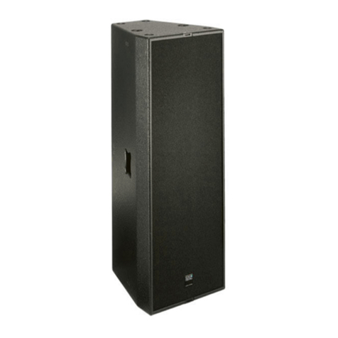
The K&F SPECTRA 212 rigging system is intended for exclusive use in the following:
1) Creating and suspending a horizontal array of up to six K&F SPECTRA 212 speakers
2) Creating and suspending a vertical array of up to four K&F SPECTRA 212 speakers
People may safely stand below the suspended structure during operation. The configuration
is designed for indoor use (trade shows, venues, etc.). Outdoor use is allowable if wind
pressures are horizontally dissipated at the top and bottom ends and the structure can be
taken down at wind forces of 8 bft or more. Be sure to use only genuine KLING & FREITAG
components. All parts must be secured against unwanted loosening.
4. Safety Instructions
Warning
The information described here does not relieve the user of the duty to follow the given
safety requirements and legal regulations.
Only technicians qualified as “riggers” are permitted to perform the installation steps. Be
sure to use personal protective equipment at all times.
The technicians responsible for installing the system on site are responsible for and
guarantee safe setup and use.
To prevent injury and damage, be sure to securely place or suspend arrays as specified in the
DGUV regulations 17 (BGV C1) or similar locally applicable accident-control standards.
Unless otherwise stated, use only KLING & FREITAG original parts for mounting the speakers.
Never use other parts (in particular, parts not made by KLING & FREITAG).
In mobile and stationary installations, always use installation parts supplied by KLING &
FREITAG.
Be sure to always visually inspect all components before use. In fixed installations, regularly
check all array components for signs of wear. Visual inspection includes checking all speaker-
system and flying components, supporting components (e.g. trusses, ceiling structures, etc.),
and all screwed connections. During the inspection, check all flying-system components
carefully for deformation, cracks, bolt damage, and corrosion. Remember checking the
ball-lock pin and pin bolts for proper functioning. Also check slings and lifts (e.g. shackles,
chains, and steel ropes) carefully for wear and deformation. If there are signs of wear,
cracks, or deformation, etc., replace the affected parts immediately. See also the “Care and
Maintenance” chapter on page 39.
Outdoor use is allowable if wind pressures are horizontally dissipated at the top and bottom
ends and the structure can be taken down at wind forces of 8 bft or more.
All connections must be secured against unwanted loosening.
