Kolpin Outdoors 25-1270 Installation and operating instructions

© 2020 Kolpin Outdoors Inc. REV 00
WINCH MOUNT KIT
FOR HONDA ATV
P/N 25-1270
ASSEMBLY / OWNERS MANUAL
Application
WINCH KIT NO. 25-9
Before you begin, please read these instructions and check to be sure all parts and tools are
accounted for. The following instructions contain details required to install and service the contents
of this kit.

2
© 2020 Kolpin Outdoors Inc. REV 00
OPERATING INSTRUCTIONS
Congratulations! You’ve just purchased the most durable accessory component in the industry. Our accessories work great all year
round! With proper care and maintenance, your Kolpin accessory will last for years to come! Please read and understand all assembly
instructions, notices and warnings before assembling and using your Kolpin accessory.
Follo these guidelines to ensure a successful and satisfactory installation:
Read, understand this manual before beginning installation
Periodically check for wear and tightness of all fasteners.
Replace or re-torque fasteners as necessary.
SAFETY & GENERAL PRODUCT INFORMATION
Kolpin accessories are designed with your safety in mind.
In order to protect you and your vehicle, certain parts of the accessory and/or hardware may be designed to collapse or break when
the equipment is over-stressed.
Kolpin winch mount kits are designed to be compatible with Kolpin and Cycle Country winches along with many others, but may not
be compatible with some winches. Kolpin winch mount kits have design features that benefit snow plow applications.
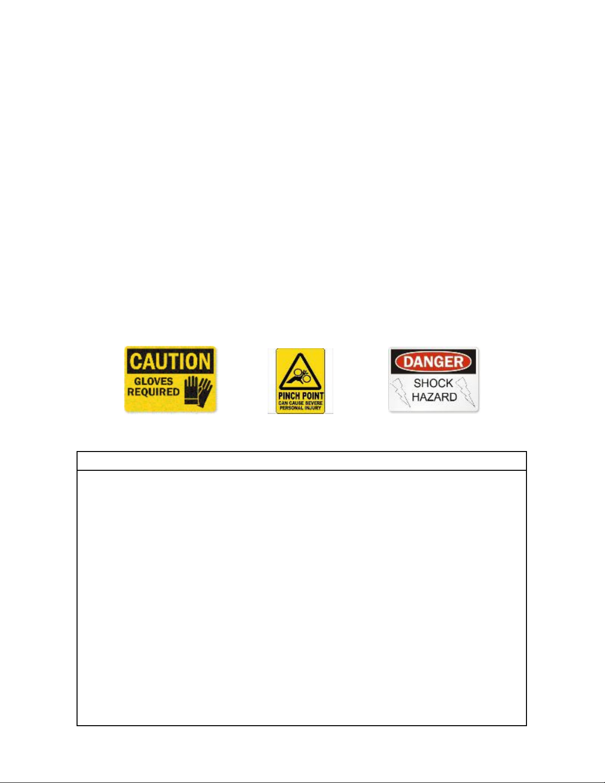
! DANGER ! ! WARNING ! ! CAUTION !
To avoid personal injury or damage to your vehicle:
Read and understand all notices for:
Caution
Warning
Danger
Follow instructions for your vehicle, winch, winch mount and other items used in combination with this product.
Do not winch unsecured loads at any time.
Disconnect battery during winch installation or service to prevent electrical hazards.
Do not lift loads overhead.
Do not e ceed the load capacity of the winch.
Always wear gloves when handling wire winch cable.
Do not use your winch or winch mount for towing.
Do not shock load the winch, cable or winch mount.
Keep fingers, hands and loose clothing away from roller fairlead and winch cable drum when in use.

3
© 2020 Kolpin Outdoors Inc. REV 00
Kit Contents:
Item Qty Part Description Part Number
11Winch Mount Bracket -
21Roller Bumper Mount Bracket -
36He Bolt, Zinc Plated, M8-1.25 20mm -
42Locknut, Zinc Plated, M8-1.25 -
51Instruction Guide (not shown) -
3 1
4
2

4
© 2020 Kolpin Outdoors Inc. REV 00
BEFORE YOU BEGIN:
• Your Kolpin accessory is exclusively designed for
your vehicle
• Please read and understand all instructions
• Verify all parts and tools are accounted for
• To ensure a satisfactory installation, follo all steps
correctly and in the sequence described
• Keep these instructions for future reference or for
informational requests
• To facilitate installation, make sure that your vehicle
is clean and free of debris
• All directions referring to right and left are hen the
rider is sitting on the machine
TOOLS REQUIRED:
• Metric rench set
• Metric socket set
• Pliers
• Do not use impact tools to install hard-
are
APPROXIMATE ASSEMBLY TIME: 30 minutes
Note: If any hardware is missing, do not return to the store. Call
us to help, Toll Free 1-877-956-5746.
Roller bracket (item #2) has
pre-drilled holes for mounting
Kolpin contactor (provided with
winch kit) onto backside of
bracket as shown in image to
the right.

5
© 2020 Kolpin Outdoors Inc. REV 00
RANCHER / FOREMAN / RUBICON
PREPARATION:
1. Shift vehicle transmission into “NUETRAL” and
set the PARKING BRAKE. Turn key to “OFF”
position and remove from vehicle.
2. Remove the OEM bolts that secure the front half
of the bottom plastic engine guard. The front half
of the plastic guard will fle downwards, providing
access to install winch kit as shown. If more
access is desired, the entire plastic guard can be
removed from vehicle. Retain bolts for use during
reinstallation. (See illustration 1-1).
3. Remove the front bumper tubing from the vehicle
as shown by removing the eight OEM fasteners
(two on front rack, two secure plastic center grille
and four attach frame tubing to vehicle main
chassis). Retain bolts for use during
reinstallation. (See illustrations 1-1, 1-2 and 1-3).
Note, the front bumper shape will vary slightly
depending on vehicle model.
4. Remove the seat and tank cover assembly from
the vehicle as shown to gain access to route
winch power cables to battery. Note, the tank
cover assembly is held into position using body
panel locating tabs pressed into rubber
grommets. Refer to the service manual for e tra
details. (See illustration 1-4).
Ill. 1-1
Fle plastic guard
Ill. 1-2
Ill. 1-3
FRONT
Bumper
bolt
Ill. 1-4
Rubber
grommets
Front
bumper
tubing

6
© 2020 Kolpin Outdoors Inc. REV 00
RANCHER / FOREMAN / RUBICON PREPARATION
(continued):
5. Remove the rear fender cover to access the battery.
Disconnect black (negative) and red (positive) cables
from battery as shown. Retain bolts for use during
reinstallation. (See illustration 1-5).
RANCHER / FOREMAN / RUBICON WINCH
INSTALLATION:
6. Position the roller mount bracket (item #2) into the front
bumper as shown. Fasten the sub-assembly into front
bumper using the M8 bolts (item #3) and M8 locknuts
(item #4). Using the hardware provided with winch kit,
install the roller fairlead (included with winch kit) onto
the roller mount bracket. (See illustrations 1-6, 1-7 and
1-8).
Note, contactor (included with winch kit) is
shown mounted in optional location on roller
bracket.
7. Tighten to specification.
Ill. 1-5
Rear fender cover
WARNING
ALWAYS disconnect black negative (-) cable
from battery FIRST. Failure to do so will result
in high current electrical arc, and may result in
battery e plosion if tool touches grounded
frame. Death or serious injury may occur.
!
!
Ill. 1-6
Ill. 1-8
8MM FASTENER TORQUE:
17 ft. lbs. (23 Nm)
Ill. 1-7
Roller
bracket
3
4
3

7
© 2020 Kolpin Outdoors Inc. REV 00
RANCHER / FOREMAN / RUBICON WINCH
INSTALLATION (continued):
8. Mount winch to winch bracket (item #1) as shown using
hardware from winch kit. Unspool a short portion of the
cable from the winch mount sub-assembly as shown.
(See illustration 1-9).
9. Position the winch/mount sub-assembly into the bumper
and align into the roller bracket (item #2) as shown.
Align the rear upper tabs of winch/mount sub-assembly
into the bumper and temporarily insert M8 bolts (item
#3) into the holes, this will help keep the mounts aligned
into the bumper. (See illustrations 1-9, 1-10, 1-11 and
1-12).
10. Fasten the winch/mount sub-assembly to the roller/
contactor sub-assembly using the M8 bolts (item #3)
inserted into the thread holes as shown. Tighten to M8
specification. (See illustrations 1-11, 1-12 and 1-13).
Ill. 1-9
Ill. 1-10
Ill. 1-12
8MM FASTENER TORQUE:
17 ft. lbs. (23 Nm)
Ill. 1-11
Winch (use
hardware
from winch
3
Threaded
holes
Ill. 1-13
3
Roller
3
Upper rear tabs

8
© 2020 Kolpin Outdoors Inc. REV 00
RANCHER / FOREMAN / RUBICON WINCH
INSTALLATION (continued):
11. Route the cable rope thru the roller fairlead and attach
the clevis hook (item #6) onto the thimble end as shown
and if equipped, the rubber bumper (item #14). The
winch cable needs to be routed thru the roller fairlead
off the top . (See illustrations 1-14 and 1-15).
Note,
accessory rubber winch stopper (sold separately as
PN 85 8 ) is shown.
12. Install front bumper-winch assembly onto the vehicle
frame using the longer M8 bolts (item #3) for the two
upper bumper locations as shown. Re-install the lower
OEM M8 screws and OEM M6 shoulder screws. Re-
install the rack mounting M8 bolt and nut. Reinstall the
plastic engine guard. (See illustrations 1-16, 1-17, 1-18,
1-19 and 1-20).
Note, the plastic engine guard can be
flexed downwards to provide install access.
13. Tighten all fasteners to specifications.
Ill. 1-14
Rope
routing
Ill. 1-15
Ill. 1-17
Plastic
engine
guard
Ill. 1-16
3
3
Lower OEM
screws
FRONT
FRONT
8MM FASTENER TORQUE:
17 ft. lbs. (23 Nm)
6MM FASTENER TORQUE:
7 ft. lbs. (9.5 Nm)

9
© 2020 Kolpin Outdoors Inc. REV 00
Ill. 1-19
Ill. 1-18
Bumper-rack
mounting
Ill. 1-20
Winch Wiring and Connections:
14. Using the winch kit instructions, route and connect the
electrical cables and components for the winch
system.
15. Secure all harnesses using cable ties (provided with
winch kit) to prevent contact with hot components,
sharp edges or moving parts.
16. Reconnect red positive (+) cable and black negative
(-) cable to battery.
17. With the vehicle key in the ON position, check winch
for proper operation.
18. Retighten all hardware after 30 minutes of riding.

10
© 2020 Kolpin Outdoors Inc. REV 00
One Year Limited Warranty
For the period of one (1) year from the purchase date, Kolpin will replace for the original purchaser,
free of charge, any part or parts found upon e amination by Kolpin to be defective in material,
workmanship, or both.
All transportation costs incurred submitting product to Kolpin for warranty consideration must be
borne by the purchaser. If Kolpin determines that the product must be returned to the factory for
credit, please call 1-877-956-5746 for a Return Merchandise Authorization (RMA) number and
shipping instructions.
This warranty does not apply to parts that have been damaged by accident, alteration, abuse,
improper maintenance, normal wear, or other causes beyond the manufacturer’s control. In order to
protect you and your ATV, certain parts of the accessory system and/or hardware are designed to
fail when the equipment is over-stressed. Parts that are lost due to loosening and improper
maintenance are not covered under warranty. This warranty does not cover removal or reinstallation
labor fees of the plow system and related components.
Peripheral products such as engines, electric motors, and actuators may carry an original
manufacturer’s warranty. Most hardware is general in nature and is easily obtained locally. Be sure
to replace with minimum metric class 8.8 specification.
Kolpin Outdoors, Inc.
Telephone: (763)-478-5800
Toll Free: (877)-956-5746
Fax Number: (800)-245-7569
.kolpin.com
Email: customerservice@kolpin.com
Table of contents
Popular Offroad Vehicle manuals by other brands

Centaur
Centaur CENTAUR Operator's manual

Polaris
Polaris 120 XC SP Universal owner's safety and maintenance manual

Yamaha
Yamaha Ultramatic GRIZZLY 660 owner's manual

ACG
ACG California Roadster eGC 2011 owner's manual

Can-Am
Can-Am DS 250 2023 Series Operator's guide

KAYO MOTOR
KAYO MOTOR AU200 Maintenance manual