Connection Interface and Wiring cables
* Caution
Do not connect the power cable until all other connections have been completed.
After removing the protection sheet (PE form), supply the power to the dome camera.
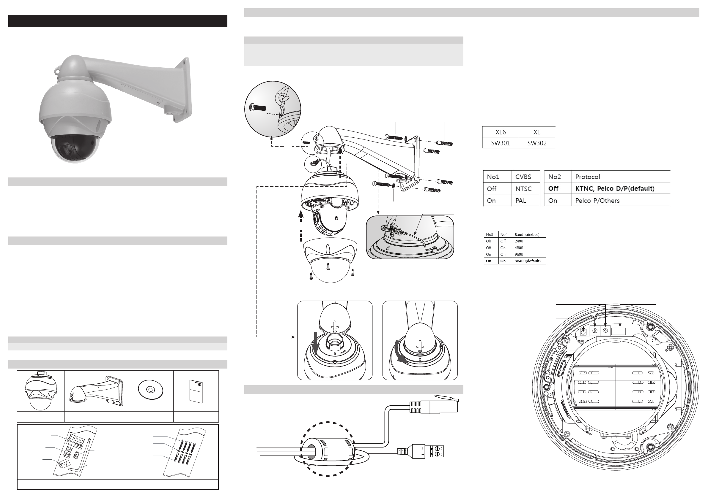
Connecting the RS-485 lines
The dome camera can be controlled remotely by an external device or control system such as a
controller using RS-485 half duplexer (RS-485 Connection). A repeater is recommended to extend
the connect ion over 1.2 Km.
Connecting Video, Audio In/Out
- Connect the video jack (BNC connector) to the portable display device
(BNC out of the dome camera is provided for installation and is not recommended for
monitoring purposes)
- Connect the audio-in jack(3.5mm) to line level audio source or MIC.
- Connect the audio-out jack(3.5mm) to speaker.
Connecting Alarms
- Alarm In: You can use external devices to trigger the dome camera to react to events.
Mechanical or electrical switches can be wired to the AL0 and GND_ARM.
- Alarm Out: The dome camera can activate external devices such as a buzzer.
Connect the device to NO (or NC) and COM pins.
Connecting the network and the power
The Network Camera connects to the network via a standard network cable, and automatically
detects the speed of the local network segment (10BaseT/100BaseTX Ethernet). PoE Supported.
If in a non-PoE power supply environment, connect the power jack(2P-terminal block) to the AC 24V
power supply. A regulated AC24V 2A(With Heater) power supply is recommended for use with this
camera for the most stable operation.
IP Address Assignment
To make it accessible on the network, the Network Camera must be assigned an IP address.
Note:
• A network DHCP server is optional.
• The Network Camera has the default IP address 192.168.0.123.
• If IP assignment fails, check that there is no firewall blocking its operation and check that the Network
Camera and your computer's IP is located on the same subnet.
Assign an IP address using IP Installer
The IP installer automatically search for and displays network devices on your
network. The application can also be used to manually assign a static IP address.
Note:
The computer running the IP installer must be on the same network segment (physical subnet) as the Network
Camera.
1. Check that the Network Camera is connected
to the network and that power has been applied.
2. Start NetCAM installer.
3. When the Network Camera appears in the window, select the Network Camera that needs to be
assigned the IP address.
A. Refresh Device List – Rescan local network to nd the Network Camera.
B. Authenticate – Enter the administrator ID and password.
C. Host Name – Enter the Host Name of the Network Camera.
D. IP Settings
i. Dynamic – Assign a dynamic IP address automatically from DHCP server on your network.
ii. Static – Assign a static IP address manually.
iii. Port – Enter the HTTP port the Network Camera will use. The default setting is 80.
Alternatively, any port in the range 1024-65535 may be used, but check rst with your
system administrator before changing the default setting.
E. Network Settings
i. Subnet Mask – Specify the mask for the subnet the Network Camera is located on.
ii. Gateway – Specify the IP address of the default router (gateway) used for connecting devices
attached to different networks and network segments.
iii. Pri. DNS – Enter the IP address of the primary DNS server. This server provides the
translation of host names to IP addresses on your network.
iv. Sec. DNS – Specify the IP address of the secondary DNS server. This will be used if the
primary DNS server is unavailable.
4. Click “Set” button to save the conguration.
Accessing the Network Camera
1. Start your browser.(when you rst run ActiveX to install, run an “IE as Administrator” on Windows or Vista)
2. Enter the IP address or host name of the Network Camera in the Address eld of your brows
3. If you are accessing the Network Camera for the rst time, you will see the following warning
message as shown below.
4. Click the warning message and select “Install ActiveX Control…”.
5. Click “Install” to install the Web Viewer.
6. If a Windows Security Alert pop-up appears, click “Unblock”.
7. After installing the Web View ActiveX Control, a Login page will be displayed.
Enter the user ID and password.
Note:
Default User ID and Password is [ID: admin, Password: admin]
8. The video image displays in your browser.
Note:
To view streaming video in Microsoft Internet Explorer, you must set your browser to allow the “KT&C Web
Viewer” to be installed on your computer. This ActiveX component is installed the first time a video stream is
accessed.
Camera ID Chart
ID S301 S302 ID S301 S302 ID S301 S302 ID S301 S302 ID S301 S302
10152 34 103 6 7 154 9 A 205 C D
20253 35 104 6 8 155 9 B 206 C E
30354 36 105 6 9 156 9 C207 CF
4 0 4 55 37 106 6 A 157 9 D208 D0
5 0 5 56 38 107 6 B 158 9 E209 D 1
6 0 6 57 39 108 6 C159 9 F 210 D 2
7 0 7 58 3A 109 6 D160 A 0 211 D 3
8 0 8 59 3B 110 6 E161 A 1 212 D 4
9 0 9 60 3 C 111 6 F 162 A 2 213 D 5
10 0 A 61 3 D 112 7 0 163 A 3214 D6
11 0 B 62 3 E 113 71164 A 4 215 D7
12 0C63 3F 114 7 2165 A 5 216 D8
13 0D64 4 0 115 7 3166 A 6 217 D9
14 0 E65 4 1116 7 4 167 A 7 218 DA
15 0 F 66 4 2117 7 5 168 A 8 219 DB
16 10 67 4 3118 7 6 169 A 9 220 D C
17 1 1 68 4 4 119 7 7 170 A A 221 D D
18 1 2 69 4 5 120 7 8 171 A B 222 D E
19 1 3 70 4 6 121 7 9 172 A C 223 D F
20 14 71 4 7 122 7 A 173 A D224 E0
21 1 5 72 4 8 123 7 B 174 A E225 E 1
22 1 6 73 4 9 124 7 C175 A F 226 E 2
23 1 7 74 4 A 125 7 D176 B 0 227 E 3
24 18 75 4 B 126 7 E177 B 1228 E4
25 19 76 4 C127 7 F 178 B 2229 E5
26 1A 77 4 D128 8 0 179 B3230 E6
27 1B 78 4 E129 8 1180 B 4 231 E 7
28 1 C 79 4 F 130 8 2181 B 5 232 E 8
29 1 D 80 5 0 131 83182 B 6 233 E 9
30 1 E 81 5 1 132 8 4 183 B 7 234 EA
31 1 F 82 5 2 133 8 5 184 B 8 235 EB
32 2 0 83 5 3134 8 6 185 B 9 236 E C
33 2 1 84 5 4 135 8 7 186 B A 237 E D
34 2 2 85 5 5 136 8 8 187 B B 238 E E
35 2 3 86 5 6 137 8 9 188 B C239 EF
36 24 87 5 7 138 8 A 189 B D240 F 0
37 25 88 5 8 139 8 B 190 B E241 F 1
38 26 89 5 9 140 8 C191 B F 242 F 2
39 27 90 5 A 141 8 D192 C0 243 F 3
40 28 91 5 B 142 8 E193 C 1 244 F 4
41 29 92 5 C143 8 F 194 C 2 245 F 5
42 2A 93 5 D144 9 0 195 C 3 246 F 6
43 2B 94 5 E145 9 1196 C4 247 F 7
44 2 C 95 5 F 146 9 2197 C5 248 F 8
45 2 D 96 6 0 147 9 3198 C6 249 F 9
46 2 E 97 6 1148 9 4 199 C7 250 F A
47 2F 98 6 2149 9 5 200 C8 251 F B
48 30 99 6 3150 9 6 201 C9 252 F C
49 3 1 100 6 4 151 9 7 202 CA 253 F D
50 3 2 101 6 5 152 9 8 203 CB 254 F E
51 3 3 102 6 6 153 9 9 204 C C 255 F F