OPENING THE UNIT
3.2
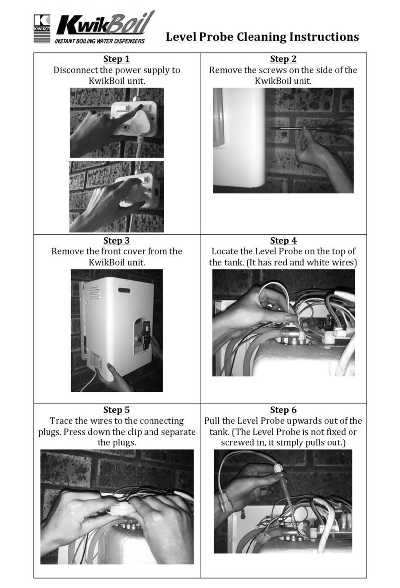
To remove the jacket from all models, remove
the retaining screws on the sides and pull the
jacket forward.
MINIMUM CLEARANCES
3.3
All units require a minimum clearance of 50
mm on all sides, however, we recommend you
leave sufficient clearance for servicing.
MOUNTING
3.4
The Kwikboil, when installed is suspended
from mounting screws located into keyhole
slots at the back of the unit (refer to the
dimension specification diagrams on pages
5,6 and 7 or the template on the carton). Be
sure that the mounting screws are securely
inserted into the keyhole slots. The screws
MUST be anchored in such a way, that they will
hold the weight of the unit when filled with
water,(refer to the weight tableon Page 8).
WATER SUPPLY
CONNECTION
3.5
Mains cold water supply ( refer to pressure
table on Page9 for operating water pressures )
must be piped and connected to the BSP
inlet fitting located on the left hand side
underneath the unit. An accessible isolating
valve must beinstalled near the unit.
1
2
''
This unit contairis a strainer on the water inlet
connection. To ensure continuing satisfactory
operation, it is suggested that theinlet strainer
be serviced every six months. Where poor
water quality is present it is recommended to
install an additionalauxiliary filter.
For rear entry connection, it is recommended
that you use a braided flexible hose with a
90 elbow for easeof connection.
VENT/OVERFLOW
CONNECTION
3.6
Connect a 15 mm (1/2") pipe to the
vent/overflow connection. (1/2" BSP). This
pipe must have a continuous fall, not
exceeding 3 metres in length, or contain no
more than 4bends.
During the normal operation of the Kwikboil
the vent/overflow connection may discharge
small quantities of steam and condensate, so
it is ESSENTIALthat the drainpipe is attached
to the vent/ overflow connection. This drain
pipe must discharge to waste at a point where
no scald injuryor inconvenience is caused.
Ensure that the vent/overflow line remains
open because the Kwikboil tank is not
designed to be pressurised. It is recom-
mended to install an air break in the
vent/overflow drain line, no more than 300
mm from theKwikboil unit.
DRAIN CONNECTION
3.7
There is a drain screw located on
the underside of the unit to
completely drain the tank for
servicing.
Before removing thedrain
screw, ensurethe appliance has
been switched off and thewater is not hot
enough to scald.
This unit is not suitable for
installation in an area where a water jet could
be used. This unit must no not
be cleaned using a water jet.
CAUTION:
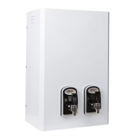
TAP OUTLET
3.8
Toprevent damage during transportation,
the tap is bubble wrapped and placed
inside the carton.
The tap is fitted to the threaded tap outlet
extension with an "o" ring seal fitted and
fixing screw to secure in the vertical
position.
Installation and maintenanceof the
Kwikboil Boiling Water Unit shall
be carried outby a suitably
qualified service person.
PLEASE NOTE:
ELECTRICAL REQUIREMENTS
3.9
All models
230 VoltsAC, 50HZ,
Single Phase
ELEMENT RATING
1800Watts 2.5 Litre
2000Watts 5 to 10 Litre
2400Watts 15 Litre
3000Watts 25 Litre
A flexible cord complete with a plug is
supplied on all models. Do not loosen the
cord grip or pull excess cord into the Kwikboil.
If the supply cord is damaged, it must be
replaced by the manufacturer or its service
agent or similarly qualified persons in order
to avoid a hazard.
THIS APPLIANCE MUST BE
EARTHED
CAUTION:
4. OPERATION
When the installation is complete, first turn
on the water supply and then switch on the
power, which will engage the solenoid valve
and the unit will automatically begin to fill and
the heating sequencewill commence.
The water is heated in small quantities, so
boiling water isavailable at all times.
The electronic control unit constantly controls
the water leveland the water temperature.
4.1 MODE 1 OPERATION:
To follow through the sequence of events in
order , it is necessary that we consider the
unit is switchedon for the first time .
When the unit is swithed on , the controller
scans the Level Probe condition , and having
established that, then executes a sequenceof
events particular tothat mode.
1.The Controller scans the Level
Probe condition. Both Probes
(low and high)will be found to be
in an OPEN condition i.e. no
water present. This then places
the unitin MODE1 condition.
1.
The solenoid valve is then
energised and the "SL" LED on the
PC-Board will light up indicate
power sent to the solenoid valve,
allowing water toenter the tank.
2.
Page 03 Page 04


