KYLAND PTS-10 User manual

www.kyland.com 3
PTS-10
Time Server
Reference
Manual

PTS Series Time Server
- 1 -
Contents
1. Features...................................................................................................................... 2
1.1. Introduction..................................................................................................2
2. LCD.............................................................................................................................. 3
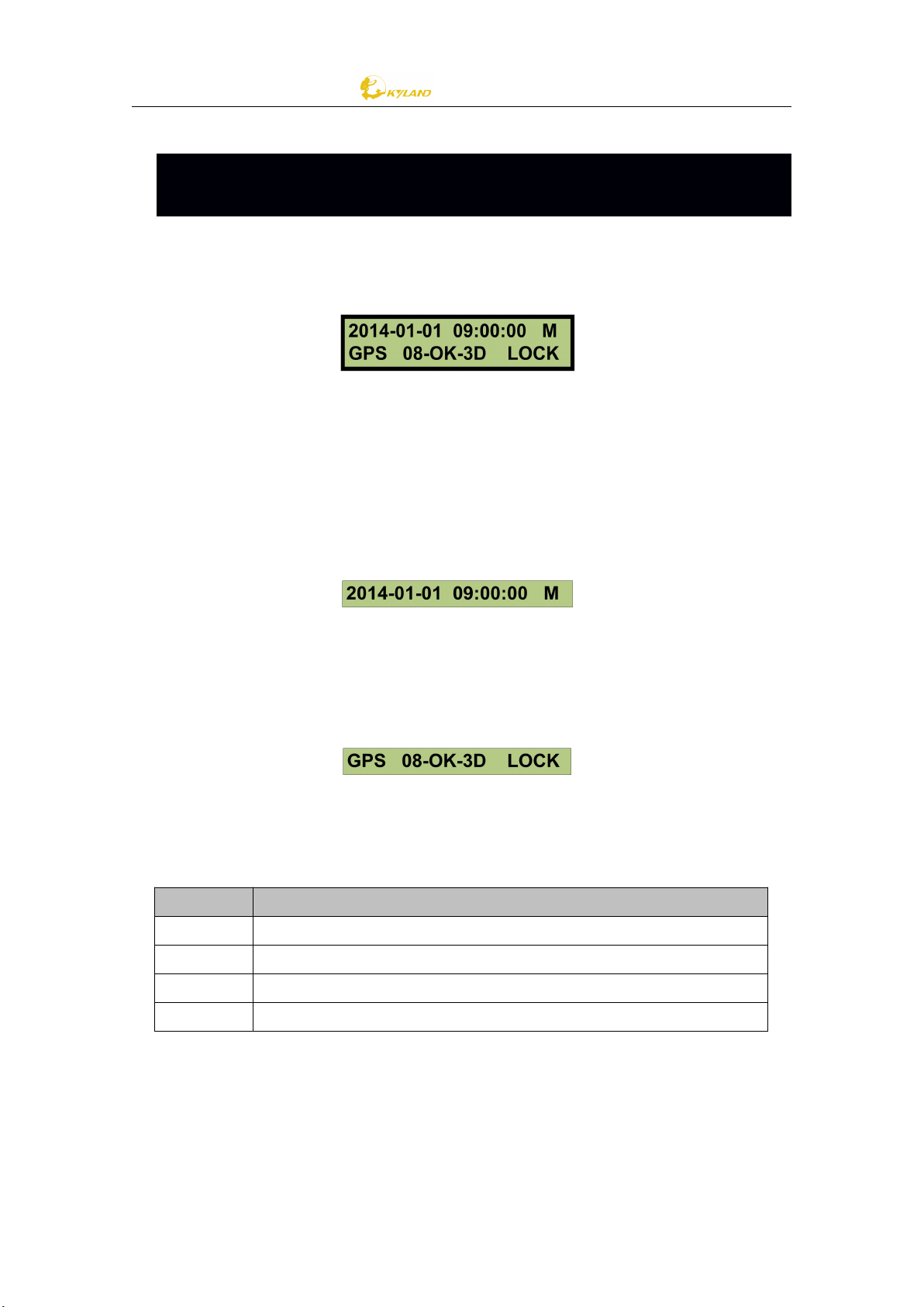
2.1. Main Screen..................................................................................................3
2.1.1. Time Infomation.................................................................................... 3
2.1.2. Status Infomation.................................................................................. 3
2.2. Indicator Light and Keys............................................................................... 3
2.3. Status Indication...........................................................................................4
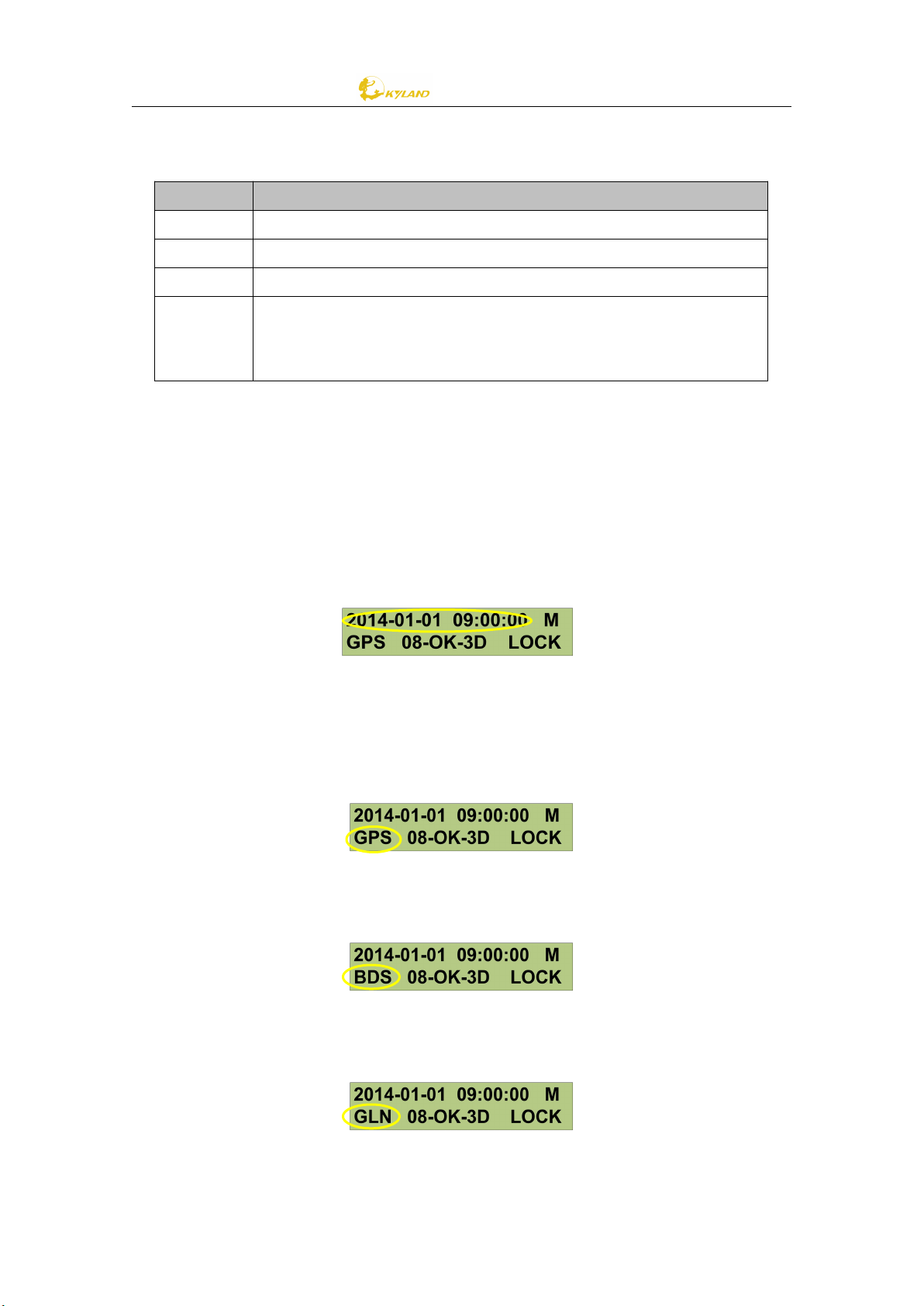
2.3.1. System Reference Time......................................................................... 4
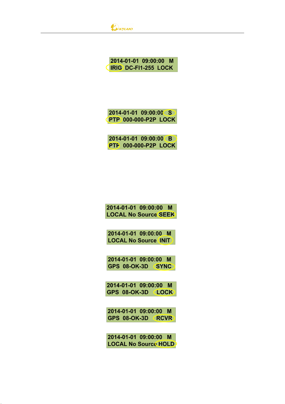
2.3.2. Time Reference Status...........................................................................4
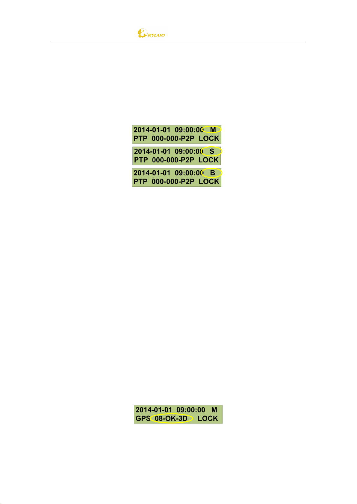
2.3.3. PTP Mode.............................................................................................. 6
2.3.4. Sync Source........................................................................................... 6
3. Operations.................................................................................................................. 9
3.1. Settings......................................................................................................... 9
3.1.1. Setting Options......................................................................................9
3.1.2. Setting Confirmation............................................................................. 9
3.2. Sync Source Settings...................................................................................10
3.3. Clock Settings............................................................................................. 12
3.4. NTP Settings............................................................................................... 12
3.5. PTP Settings................................................................................................ 12
3.6. Output Settings.......................................................................................... 14
3.6.1. SO Output............................................................................................14
3.6.2. O1-O5 Output......................................................................................14
3.6.3. IRIG-B-AC Output................................................................................ 15
3.7. Network Settings........................................................................................ 15
Figure Index.....................................................................................................................17

PTS Series Time Server
- 2 -
1. Features
1.1. Introduction
[Figure 1- 1] PTS-10 Time Server
The PTS-10 Time Server is a standard time server. It supports high precision reference
clock, which can be synchronized to absolute time such as GPS, BDS, and GLONASS.
The reference clock can also be synchronized to local time source through an external
IRIG-B interface, PPS interface or other local time sources. Built-in OXCO help to
provide stable reference frequency source. System supports multiple sources time
sync auto selection algorithm which can perform stable switch between GPS, BDS,
GLONASS, IRIG-B, PTP and local clock, and sky/ground and master/slave clock backup.
PTS time server provides flexible time synchronization signal output slots which can
help to configure different timing output interface channel. The output timing
channels include PPS, PPM, 10M, IRIG-B (DC), IRIG-B (AC), Serial Time Signal (TOD etc.)
etc. Plus, PTS-10 supports network sync time protocols NTP/SNTP/ IEEE1588 V2.0.
IEEE1588 works in several modes by the software configuration including grandmaster
clock, slave clock and boundary clock. PTS-10 has LCD to show any status and do
configuration by keyboard. Meanwhile, PTS-10 is designed to send timing source
status and clock status to control center by IEC61850 MMS, IEC60870-T104, DNP3.0,
Modbus, etc.

PTS Series Time Server
- 3 -
2. LCD
2.1. Main Screen
The default main screen is shown as below:
[Figure 2- 1] PTS-10 Main Screen
The screen has two line characters. The top line always shows the time information.
The bottom line shows time server status.
2.1.1. Time Infomation
Time information includes time as the following format yyyy-mm-dd hh:mm:ss and PTP work
mode as M (Master), S (Slave) and B (Boundary).
[Figure 2- 2] PTS-10 Time Information
2.1.2. Status Infomation
Time server shows the current time source status and clock status. The detail information please
refers to section 2.3.
[Figure 2- 3] PTS-10 Status Information
2.2. Indicator Light and Keys
Press any key of front panel to view information and change parameters.
Name
Description
UP
Show information as UP direction.
DOWN
Show Information as DOWN direction.
Enter
Confirm operation.
ESC
Cancel operation or Back to high level

PTS Series Time Server
- 4 -
Indicator light of front panel shows time server status.
Name
Description
PSW
On: Power On; Off: Power Off
SAT
On: Satellite Number >=4; Off: Satellite Number <4
ANT
On: Antenna is normal; Off: Antenna is abnormal
LOCK
Flash(1 second): Clock is locked;
Flash(3 seconds):Clock is holded;
Off: Clock is unlocked
NOTE: When screen backlight is off, press any key will ative screen again.
2.3. Status Indication
Time server will be shown as the following screen.
2.3.1. System Reference Time
The system reference time is shown at the first part of top line.
The time format is YYYY-MM-DD HH:MM:SS.mmm.
[Figure 2-4] System Reference Time
2.3.2. Time Reference Status
The time reference status is shown at bottom line.
For GPS time reference source, the first part of line named GPS is shown below.
[Figure 2-5] Time Reference (GPS)
For BDS time reference source, the first part of line named BDS is shown below.
[Figure 2-6] Time Reference (BDS)
For GLONASS time reference source, the first part of line named GLN is shown below.
[Figure 2-7] Time Reference (GLONASS)

PTS Series Time Server
- 5 -
For IRIG-B time reference source, the first part of line named IRIG is shown below.
[Figure 2-8] Time Reference (IRIG-B)
For PTP time reference source (i.e., the PTS-10 is working as PTP Slave Clock and
Boundary Clock), the first part of line is named PTP.
[Figure 2-9] Time Reference (PTP-Slave)
[Figure 2-10] Time Reference (PTP-Boundary)
For any kind of time reference source, the last part of line always shows time
synchronization mode. For seeking status, ‘SEEK’ is displayed; for initial status, ‘INIT’ is
displayed; for sync status, ‘SYNC’ is displayed; for lock status, ‘LOCK’ is displayed; for
time adjust status, ‘RCRV’ is displayed; for hold status, ‘HOLD’ is displayed.
[Figure 2-11] Sync Lock Mode (SEEK)
[Figure 2-12] Sync Lock Mode (INIT)
[Figure 2-13] Sync Lock Mode (SYNC)
[Figure 2-14] Sync Lock Mode (LOCK)
[Figure 2-15] Time Setting Mode (RCVR)
[Figure 2-16] Hold Mode (HOLD)

PTS Series Time Server
- 6 -
2.3.3. PTP Mode
The PTP mode is shown at last part of top line. The PTS-10 might work in one of the
following modes:
Master
PTP Grandmaster Clock
Slave
PTP Slave Clock
Boundary
PTP Boundary Clock
[Figure 2-17] PTP Mode
2.3.4. Sync Source
The sync source is shown at middle part of bottom line. The display format depends
on the sync source.
Use GPS as sync source, the display format is shown below:
GPS:xx Ant:xx Fix:xx
GPS
The amount of locked GPS satellites at present.
Ant
GPS antenna status. Following is the status introduction:
OK: antenna normal
UV: low antenna power supply voltage
NV: no antenna power supply voltage
OC: antenna over current
Fix
GPS fix mode. Following is the mode introduction:
3D: The best fix mode.
2D: 2D fix mode. Not enough tracked satellites
HD: Hold over. Just lost the tracking to satellites, but time
accuracy should be OK.
No: No fix. No satellites are tracked.
[Figure 2-18] Sync Source: GPS

PTS Series Time Server
- 7 -
Use BDS as sync source, the display format is shown below:
BDS:xx Ant:xx Fix:xx
BDS
The amount of locked BDS satellites at present.
Ant
BDS antenna status. Following is the status introduction:
OK: antenna normal
UV: low antenna power supply voltage
NV: no antenna power supply voltage
OC: antenna over current
Fix
BDS fix mode. Following is the mode introduction:
3D: The best fix mode.
2D: 2D fix mode. Not enough tracked satellites
HD: Hold over. Just lost the tracking to satellites, but time
accuracy should be OK.
No: No fix. No satellites are tracked.
[Figure 2-19] Sync Source: BDS
Use GLONASS as sync source, the display format is shown below:
GLN:xx Ant:xx Fix:xx
GLN
The amount of locked GLONASS satellites at present.
Ant
GLONASS antenna status. Following is the status introduction:
OK: antenna normal
UV: low antenna power supply voltage
NV: no antenna power supply voltage
OC: antenna over current
Fix
GLONASS fix mode. Following is the mode introduction:
3D: The best fix mode.
2D: 2D fix mode. Not enough tracked satellites
HD: Hold over. Just lost the tracking to satellites, but time
accuracy should be OK.
No: No fix. No satellites are tracked.
[Figure 2-20] Sync Source: GLONASS
Use IRIG-B as sync source, the display format is shown below:

PTS Series Time Server
- 8 -
IRIG-B-xx-xxx Frame: xxx
IRIG-B
IRIG-B input format. Following is the format introduction:
DC: IRIG-B DC
AC: IRIG-B AC
Modified Manchester Code
Frame
The number of IRIG-B input source frame
[Figure 2-21] Sync Source: IRIG-B-DC
Use PTP as sync source, the display format is shown below:
Off: xxxxxx Mode Delay: xxxxxx
Off
PTP Offset, the unit is ns
Mode
PTP Mode, E2E or P2P
Delay
PTP Delay, the unit is ns
[Figure 2-22] Sync Source (PTP-P2P)
[Figure 2-23] Sync Source (PTP-E2E)
Notes: When offset or delay is more than ±999999ns, character’*’ is displayed instead
of a number.

PTS Series Time Server
- 9 -
3. Operations
3.1. Settings
LCD screen might show data by ‘UP/DOWN’ key. Press ‘Enter’ key on any screen might
enter setting screen.
3.1.1. Setting Options
On main screen, select ‘Enter’ key to enter to setting configuration screen.
[Figure 3-1] Configuration Screen
Name
Description
Note
SYN
Sync source
settings
Set the external clock source including GPS, BDS, GLONASS,
IRIG-B, and PTP. Also set the priority for signal source, IRIG-B
time service and antenna time delay compensation, etc.
CLK
Clock settings
Set reference time as UTC or TAI, time zone offset and output
modes, etc.
NTP
NTP settings
Set NTP timing signal output, and time zone offset between
UTC in hour.
PTP
PTP settings
Set timing modes, sync time interval, delay time interval,
priority and vLAN etc.
OUT
Output settings
Set the output channel SO,O1~O5, and the output signal,
signal delay compensation, polarity, etc.
NET
Network settings
Set network IP address, subnet mask and operating modes.
3.1.2. Setting Confirmation
Any modified settings should be accepted password confirm. If wrong password, the
new configuration will not work.
As the following steps to finish password confirm:
Password Verify Screen
Use ‘UP/DOWN’ key to select password, then press ‘Enter’ key to confirm.
NOTE: The default password is 8.

PTS Series Time Server
- 10 -
[Figure 3-2] Configuration Screen
Password Invalid Screen
Input wrong password, the following tips will be shown:
[Figure 3-3] Invalid Password Screen
Password Valid Screen
Input correct password, the following tips will be shown:
[Figure 3-4] Valid Password Screen
3.2. Sync Source Settings
In main screen, press ‘SYNC’ button to modify sync source settings. Various sync
source settings are provided by the page switch buttons. There are totally 3 pages
available.
[Figure 3-5] Sync Source Setting: Page 1
Name
Description
Parameter
Note
WORK
MODE
Working Mode
Single /Multple
Single source enabled(only one good
external source can make clock
work)/multi-source enabled(compare
with multiple good time sources in
order to select best one as the
reference source)
[Figure 3-6] Sync Source Setting: Page 2,3
Name
Description
Parameter
Note
SAT1-T
Satellite Type
UBLOX5/UBLOX8/H
Set satellite receiver model.

PTS Series Time Server
- 11 -
SAT2-T
WA200
SAT1-M
SAT2-M
Satellite Mode
Auto/A-BDS/A-
GPS/A-GLN/F-
BDS/F-GPS/F-GLN
Set satellite receiver working mode.
SAT1-A
SAT2-A
Satellite Antenna
Compensation
0ns
According to different antenna types
and lengths, system implements time
delay compensation.
[Figure 3-7] Sync Source Setting: Page 4,5
Name
Description
Parameter
Note
SAT1-P
SAT1 Priority
1~10
Set the priority for external signal
source. 1 is highest source and 10 is
lowest source.
SAT2-P
SAT2 Priority
B01-P
IRIG-B1 Priority
B02-P
IRIG-B2 Priority
PTP-P
PTP Priority
[Figure 3-8] Sync Source Setting: Page 6,7
Name
Description
Parameter
Note
SAT1-W
SAT1 Mode
SYNC/PEER/NONE
To set source working mode. SYNC is
individual sync source, PEER is
redundancy sync source and NONE is
anything to do.
SAT2-W
SAT2 Mode
B01-W
IRIG-B1 Mode
B02-W
IRIG-B2 Mode
PTP-W
PTP Mode
[Figure 3-9] Sync Source Setting: Page 8,9
Name
Description
Parameter
Note
B1CHA
IRIG-B1/2 Input
FI1/FI2
To set IRIG-B1/B2 input time signal.

PTS Series Time Server
- 12 -
B2CHA
B1FOR
B2FOR
IRIG-B1/2 Format
DC+/DC-/MC/AC
To set IRIG-B1/B2 input format,
including DC+ (positive polarity DC), DC-
(negative polarity DC), MC (Manchester)
and AC (modulated) IRIG-B signal.
B1OFF
B2OFF
IRIG-B1/B2 UTC
0.00H
Set time offset between IRIG-B and
UTC.
3.3. Clock Settings
[Figure 3-10] Clock Setting: Page 1
Name
Description
Parameter
Note
USE
Use UTC
UTC / TAI
Set UTC time or TAI time as required
OUT
Output Mode
Always/Lock
Always means time server always has
output signals in any time. Lock means
time server only has output signals after
timer server is locked by external time
source.
ZONE
Time Zone
0.00H
Set time zone offset to ensure required
time zone display.
TAIOFF
TAI and UTC Offset
35s
Set time zone offset between TAI and
UTC.
3.4. NTP Settings
[Figure 3-11] NTP Setting: Page 1
Name
Description
Parameter
Note
NTP-S
NTP Server
Enable/Disable
To enable or disable NTP server of time
server.
NTPOFF
NTP and UTC Offset
0.00H
Set time offset between NTP and UTC.
3.5. PTP Settings
[Figure 3-12] PTP Setting: Page 1

PTS Series Time Server
- 13 -
Name
Description
Parameter
Note
MODE
PTP Mode
Master/Slave
/Boundary
Set PTP working mode.
PATH
Delay Measurement
Mode
E2E / P2P / Disable
Set clock delay measurement mode or
disable this function.
LOG-S
Sync Interval
-8~4 / Stop
Set the PTP sync message rate of PTP
master clock. Setting value is n, actual
interval is 2nseconds. Valid range is
from -8 to 4 and Stop. Default value is
Stop.
LOG-D
Delay Measurement
Interval
-8~4 / Stop
Set delay measurement rate. Setting
value is n, actual interval is 2nseconds.
Valid range is from -8 to 4 and Stop.
Default value is Stop.
[Figure 3-13] PTP Setting: Page 2
Name
Description
Parameter
Note
DOM1/2
Domain1/2
0~3
Set the working domain name for PTP
message.
PRI1/2
Priority1/2
0~255
Set working priority for PTP message.
[Figure 3-14] PTP Setting: Page 3
Name
Description
Parameter
Note
MEDIA
Over Media
802.3 / IPv4
Set the transmission protocol for
PTP.IEEE802.3 and IPv4 are supported.
INDELAY
Receive Delay
0ns
Set the time delay for receiving PTP
message.
OUTDELAY
Send Delay
0ns
Set the time delay for sending PTP
message.
[Figure 3-15] PTP Setting: Page 4
Name
Description
Parameter
Note
VLAN
Enable Vlan
Yes / No
Set whether to send vLan information.
VLAN-P
vLan Priority
0~7
Set vLan priority.

PTS Series Time Server
- 14 -
VLAN-ID
vLan ID
0~4095
Set vLan ID information.
3.6. Output Settings
[Figure 3-16] Output Setting
Name
Description
SO
Config serial output time signals.
O1
Config channel 1 output time signals.
O2
Config channel 2output time signals.
O3
Config channel 3 output time signals.
O4
Config channel 4 output time signals.
O5
Config channel 5 output time signals.
AC
Config IRIG-B-AC time signals.
3.6.1. SO Output
[Figure 3-17] SO Output Setting: Page 1
Name
Description
Parameter
Note
PPS
SO-PPS signal
PPS/IRIG/PPM/10M
Set the signal type for the SO-PPS.
TXD
SO-TxD Signal
TOD
Set the signal type for SO-TxD.
TIME
SO Time Format
UTC / TAI / Local
Set SO output time format which can be
set to UTC/TAI/Local time.
TYPE
SO Message
RMC,ZDA,DL/T1100,
CM-TOD,CMBB
Set the coding format for serial port
message.
BAUD
SO BaudRate
300~115200
Set the working baud rate for serial
port, ranging from 300 to 115200.
[Figure 3-18] SO Output Setting: Page 2
Name
Description
Parameter
Note
S-OFF
SO Offset
0s
Set SO second offset.
PPS-OFF
SO-PPS Offset
0ns
Set SO-PPS offset.
3.6.2. O1-O5 Output

PTS Series Time Server
- 15 -
[Figure 3-19] O1~O5 Output Setting: Page 1
Name
Description
Parameter
Note
O1~O5
O1~O5 time
signals
PPS/IRIG/PPM/10M
Set the signal type for the O1~05. The
BDC means IRIG-B-DC signal.
S-OFF
IRIG-B Offset
0s
Set second offset for IRIG-B.
PPS-OFF
IRIG-B PPS Offset
0ns
Set PPS offset for PPS1~5.
[Figure 3-20] O1~O5 Output Setting: Page 2
Name
Description
Parameter
Note
IRIG-C
IRIG-B Check Bit
Even /Odd
Set IRIG-B check code: even check, odd
check.
IRIG-P
IRIG-B Polarity
+/-
Set IRIG-B output signal polarity.
IRIG-T
IRIG-B Time
UTC/TAI/Local
Set IRIG-B output time format which
can be set to UTC/TAI/Local time.
3.6.3. IRIG-B-AC Output
[Figure 3-21] AC Output Setting: Page 1
Name
Description
Parameter
Note
AC-PEAK
IRIG-AC
Output P-P
3.OV~12.0V
Set the peak-to-peak value for IRIG-B-
AC, ranging from 3.0V to 12.0V,
adjusting step length is 0.5V, default
value is 12.0V.
AC-Ratio
IRIG –AC
Output Ratio
3.0:1~6.0:1
Set the modulation ratio for IRIG-B-AC,
ranging from 3.0:1~6.0:1, adjusting step
length is 0.5:1; default value is 3.0:1.
3.7. Network Settings
[Figure 3-22] Network Setting: Page 1
Name
Description
Parameter
Note
IP0
IP Address
192.168.0.111
Set ETH0 IP address, the default is

PTS Series Time Server
- 16 -
192.168.0.111.
MS0
Mask Address
255.255.255.0
Set ETH0 Subnet mask address, the
default is 255.255.255.0.
MO0
Network Mode
Auto/Force
Set ETH0 mode.
[Figure 3-23] Network Setting: Page 2
Name
Description
Parameter
Note
IP1
IP Address
192.168.1.111
Set ETH1 IP address, the default is
192.168.1.111.
MS1
Mask Address
255.255.255.0
Set ETH1 Subnet mask address, the
default is 255.255.255.0.
MO1
Network Mode
Auto/Force
Set ETH1 mode.
[Figure 3-24] Network Setting: Page 3
Name
Description
Parameter
Note
IP2
IP Address
192.168.2.111
Set ETH2 IP address, the default is
192.168.2.111.
MS2
Mask Address
255.255.255.0
Set ETH2 Subnet mask address, the
default is 255.255.255.0.
[Figure 3-25] Network Setting: Page 4
Name
Description
Parameter
Note
IP3
IP Address
192.168.3.111
Set ETH3 IP address, the default is
192.168.3.111.
MS3
Mask Address
255.255.255.0
Set ETH3 Subnet mask address, the
default is 255.255.255.0.
When change any options in the main screen, user can use the navigation button ‘UP’
and ‘DOWN’ key to switch the settings page. Press ‘Enter’ key to set parameters.
According to screen tips, select or type the correct settings.

PTS Series Time Server
- 17 -
Figure Index
[Figure 1- 1] PTS-10 Time Server.............................................................................................................2
[Figure 2- 1] PTS-10 Main Screen............................................................................................................3
[Figure 2- 2] PTS-10 Time Information....................................................................................................3
[Figure 2- 3] PTS-10 Status Information..................................................................................................3
[Figure 2- 4] System Reference Time...................................................................................................... 4
[Figure 2- 5] Time Reference (GPS).........................................................................................................4
[Figure 2- 6] Time Reference (BDS).........................................................................................................4
[Figure 2- 7] Time Reference (GLONASS)................................................................................................4
[Figure 2- 8] Time Reference (IRIG-B)..................................................................................................... 5
[Figure 2- 9] Time Reference (PTP-Slave)................................................................................................5
[Figure 2- 10] Time Reference (PTP-Boundary)...................................................................................... 5
[Figure 2- 11] Sync Lock Mode (SEEK).....................................................................................................5
[Figure 2- 12] Sync Lock Mode (INIT)......................................................................................................5
[Figure 2- 13] Sync Lock Mode (SYNC).................................................................................................... 5
[Figure 2- 14] Sync Lock Mode (LOCK)....................................................................................................5
[Figure 2- 15] Time Setting Mode (RCVR)...............................................................................................5
[Figure 2- 16] Hold Mode (HOLD)........................................................................................................... 5
[Figure 2- 17] PTP Mode......................................................................................................................... 6
[Figure 2- 18] Sync Source: GPS.............................................................................................................. 6
[Figure 2- 19] Sync Source: BDS.............................................................................................................. 7
[Figure 2- 20] Sync Source: GLONASS..................................................................................................... 7
[Figure 2- 21] Sync Source: IRIG-B-DC.....................................................................................................8
[Figure 2- 22] Sync Source (PTP-P2P)......................................................................................................8
[Figure 2- 23] Sync Source (PTP-E2E)......................................................................................................8
[Figure 3- 1] Configuration Screen.......................................................................................................... 9
[Figure 3- 2] Configuration Screen........................................................................................................10
[Figure 3- 3] Invalid Password Screen................................................................................................... 10
[Figure 3- 4] Valid Password Screen......................................................................................................10
[Figure 3- 5] Sync Source Setting: Page 1..............................................................................................10
[Figure 3- 6] Sync Source Setting: Page 2,3.......................................................................................... 10
[Figure 3- 7] Sync Source Setting: Page 4,5.......................................................................................... 11
[Figure 3- 8] Sync Source Setting: Page 6,7.......................................................................................... 11
[Figure 3- 9] Sync Source Setting: Page 8,9.......................................................................................... 11
[Figure 3- 10] Clock Setting: Page 1...................................................................................................... 12

PTS Series Time Server
- 18 -
[Figure 3- 11] NTP Setting: Page 1........................................................................................................ 12
[Figure 3- 12] PTP Setting: Page 1.........................................................................................................12
[Figure 3- 13] PTP Setting: Page 2.........................................................................................................13
[Figure 3- 14] PTP Setting: Page 3.........................................................................................................13
[Figure 3- 15] PTP Setting: Page 4.........................................................................................................13
[Figure 3- 16] Output Setting................................................................................................................ 14
[Figure 3- 17] SO Output Setting: Page 1..............................................................................................14
[Figure 3- 18] SO Output Setting: Page 2..............................................................................................14
[Figure 3- 19] O1~O5 Output Setting: Page 1....................................................................................... 15
[Figure 3- 20] O1~O5 Output Setting: Page 2....................................................................................... 15
[Figure 3- 21] AC Output Setting: Page 1.............................................................................................. 15
[Figure 3- 22] Network Setting: Page 1.................................................................................................15
[Figure 3- 23] Network Setting: Page 2.................................................................................................16
[Figure 3- 24] Network Setting: Page 3.................................................................................................16
[Figure 3- 25] Network Setting: Page 4.................................................................................................16
Table of contents