La Pavoni P300 User manual

P300
Cod. 2850012 - Rev. 00 ENG - Ottobre 2008

Pag. 2
INDEX
Technical characteristics -----------------------3
Installation----------------------------------------4
Operating -----------------------------------------7
Programmation-----------------------------------8
frequent menu ---------------------------8
set drinks ---------------------------------9
set prices----------------------------------10
counters & amounts---------------------11
events ------------------------------------12
main menu -------------------------------14
set time--------------------------------15
payment system----------------------16
set temperature-----------------------17
options --------------------------------18
1st level --------------------------19
2nd level -------------------------20
set drinks -----------------------------23
quick functions --------------------------27
Troubleshooting guide--------------------------28
Hydraulic circuit---------------------------------29
Electrical diagram -------------------------------30
Pag. 31
ELECTRIC CIRCUIT LEGEND
F anti-interference filter
TR transformer 230Vac / 24 – 20 Vac 170VA
I.P. door safety switch
CX safety thermostat 145°C
R.C. boiler heating element 230V 1200W
R.G. espresso group heating element
V ventilator
CV flowmeter
PS soluble pump
PC espresso pump
MG espresso group motor
EV-A hot water Electro valve
MS5 doser motor soluble 5
MS4 doser motor soluble 4
MS3 doser motor soluble 3
MS2 doser motor soluble 2
MS1 doser motor soluble 1
MZ “sugar in cup” doser motor
EM-G to the obliterator coil (24Vdc)
M-CB cup turret motor
M-SB cup releaser motor
EM-C coffee releaser coil
EM-P spoon releaser coil
E-S4/5 soluble 4 & 5 electro valve
F-S4/5 soluble 4 & 5 whipper
E-S1/2 soluble 1 & 2 electro valve
F-S1/2 soluble 1& 2 whipper
E-S3 soluble 3 electro valve
F-S3 soluble 3 whipper
EV-C espresso coffee electro valve
M-M grinder motor
S boiler temperature probe
S-PB “cup” position sensor
G.R. espresso group “normal” position sensor
GET “token” microswitch
S-B “cup” sensor
MB cup-releaser motor
S-PE “supply” position sensor
S-PZ “sugar” position sensor
M.B. cup-releaser switch
D.C. coffee-doser switch
V.A. lack water switch (float)
G.E. espresso group “supply” position micro switch

Pag. 30
ELECTRIC DIAGRAM
Pag. 3
TECHNICAL CHARACTERISTICS
Dimensions: Height 162 cm
Width 48.5 cm
Depth 55 cm
Weight: 90 Kg
Voltage supply: 230 Vac. 50 Hz or 120 Vac. 60Hz on request
Absorbed power: 1,6 KW
Selections: n°14 for F300 model
n°28 for F306 model
Possibility to program up to 40 selections.
Payment system: predisposed for
• Obliterator / token system 24Vdc
• Parallel selector 12Vac or 24Vac
• Executive / MDB system
Water connection: inside tank 15lit.
From water system with male fitting of ¾" (optional)
Cups capacity: up to 300
Stirrers capacity: up to 300
Optional:
• connection kit to the water net
• double pump
• beniamino filter (anti-limestone filter)
• whipper for powder container position 3 (mod. Plus)

Pag. 4
INSTALLATION
Before proceeding to the operations of installation, maintenance and reparation of
the machine, read the manual carefully, where there is contained the necessary
information for the correct use of the machine.
Install the machine in a dry and not dusty place.
Put to level the machine through the regulation of the feet.
ELECTRIC CONNECTION
Before connecting the machine to the power, follow the following instructions:
o check that the electric line has a suitable course for the absorbed power
(1600W)
o check that the voltage corresponds to the data indicated in the plate on the left
side of the machine.
o The power has to have the efficient earth connection..
o In case of substitution of the cable of feeding, use only original cables (ask to
the manufacturer the special cable with type M connection)
The manufacturer will not take on any responsibility if these instruc-
tions are not respected.
All the electric devices in the machine work with a 24Vdc produced by the trans-
former except the boiler heating element and the same transformer, that use a ten-
sion of 230Vac or 120Vac on request.
The main light switch is a bipolar type and it supplies all the machine.
There are two fuses, 2A and 12A, which respectively protect the transformer and
the circuit in low voltage 24Vdc.
In case you have to extract the breakdown fuses, unscrew the hood container.
The 20Vac low-power circuit is interrupted by a safety button, situated on the
chassis, that cuts the current to the electronic board when the door is open.
Extracting the button, it is possible to reestablish the feeding with the door open
(by only technical staff).
Pag. 29
HYDRAULIC CIRCUIT
Legend:
EV Inlet electrovalve UC espresso group outlet
D anti-limestone filtrer (optional) U1 mixer 1 outlet
VA water reservoir (optional) U2 mixer 2 outlet
CV flowmeter U3 mixer 3 outlet
PS soluble pump
PC espresso pump
V one-way valve
C boiler
EV1 soluble 1 & 2 electrovalve
EV2 soluble 3 and hot water electrovalve
EV3 soluble 4 & 5 electrovalve
EvE espresso electrovalve
M1 soluble 1 & 2 mixing group
M2 soluble 3 mixing group
M3 soluble 4 & 5 mixing group
GE espresso group
S espresso waste electrovalve

Pag. 28
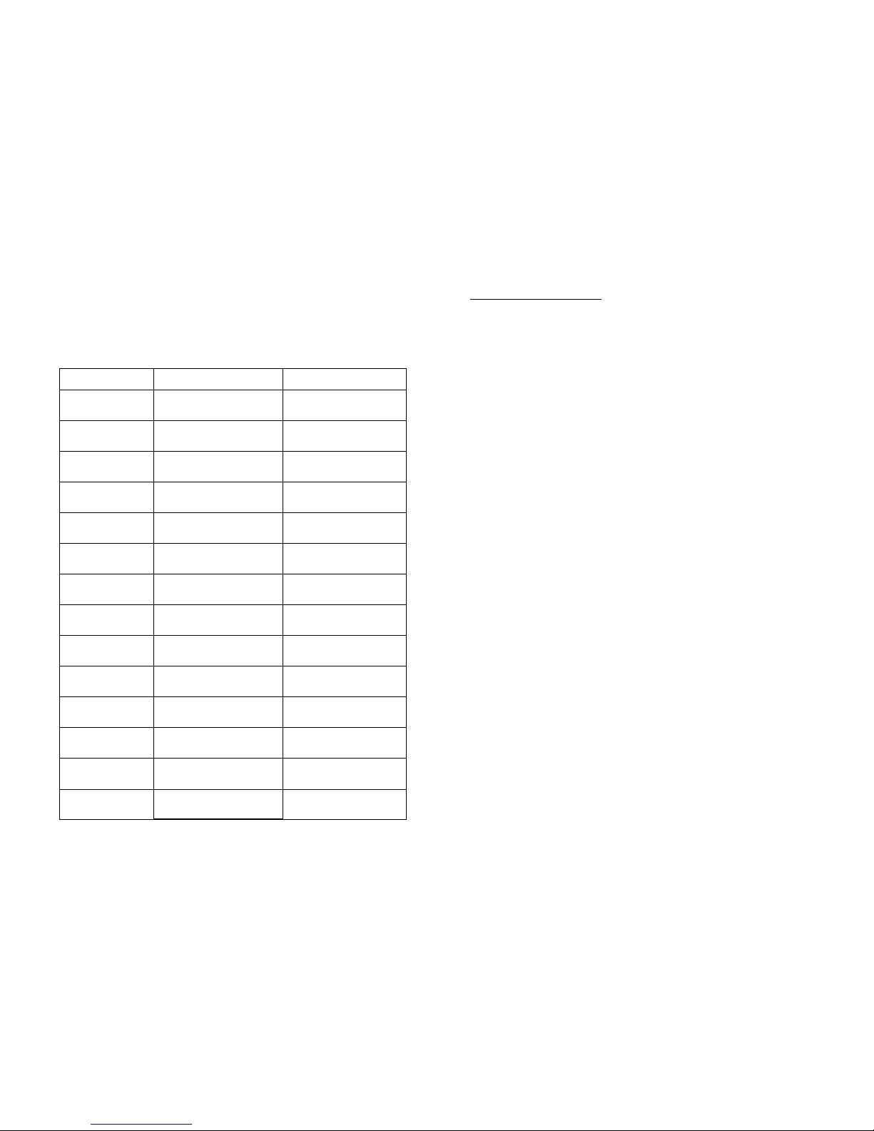
TROUBLESHOOTING GUIDE
The machine is provided with a program of self-diagnosis, that allows to visualize
on the display the messages of breakdown or machine stopped :
Message Description Probable cause
ERR. CUP-RELEAS. during the cup-releasing, the board has not
received the change of state of the cup-releaser
micro switch.
Fuses, cup-releaser motor, cup-releaser micro
switch, electronic board.
ERROR ARM 0 The electronic board has not received the “sugar
position” of the cup -arm signal by the relative
sensor on the cup-station board.
Fuses, cup blocked in the cup-arm, cup-arm
motor, position sensor, electronic board.
ERROR ARM 1 The electronic board has not received the “cup
position” of the cup -arm signal by the relative
sensor on the cup-station board.
Fuses, cup blocked in the cup-arm, cup-arm
motor, position sensor, electronic board.
ERROR ARM 2 The electronic board has not received the
“supply position” of the cup -arm signal by the
relative sensor on the cup-station board.
Fuses, cup blocked in the cup-arm, cup-arm
motor, position sensor, electronic board.
ERROR GROUP 1 the coffee-group has not reached the “supply
position” given by its right micro switch. Fuses, group right micro switch, group motor,
electronic board.
ERROR GROUP 0 the coffee-group has not reached the “normal
position” given by its left micro switch. Fuses, group left micro switch, group motor,
electronic board.
ERR. COFFEE FLOW During espresso supplying, the board has not
received signals from the flowmeter. Fuses, too finer coffee, coffee pump, coffee
electro valve, flowmeter, electronic board.
ERR. SOLUB.FLOW During soluble supplying, the board has not
received signals from the flowmeter. Fuses, solubile pump, solubile electro valve,
flowmeter, electronic board.
ERROR GRINDER 1 During the coffee grinding, the board has not
received the signal given by the doser-switch in
the maximum time of 25 seconds.
Too fine coffee, fuses, doser micro-switch,
grinder motor, grinder blocked by something
hard, electronic board.
LACK OF CUPS The board doesn’t receive the signal from the
cups sensor. Lack of cups, cups sensor, electronic board.
LACK OF WATER The board doesn’t receive the signal from the
float. Lack of water, float, water container micro
switch, electronic board.
ERROR BOILER 1 The board has not received the programmed
value temperature from the boiler probe in the
maximum time of 15 minutes.
Safety thermostat, boiler heating element,
electronic board.
EMPTY GROUNDS! The coffee grounds decounter has reached the
programmed value. Empty the grounds and execute the quick
function nr.5.
ERROR EXECUTIVE At the power-on, the board has not received
signals by the payment payment, Executive or
MDB, programmed.
Payement system, cables, electronic board..
Pag. 5
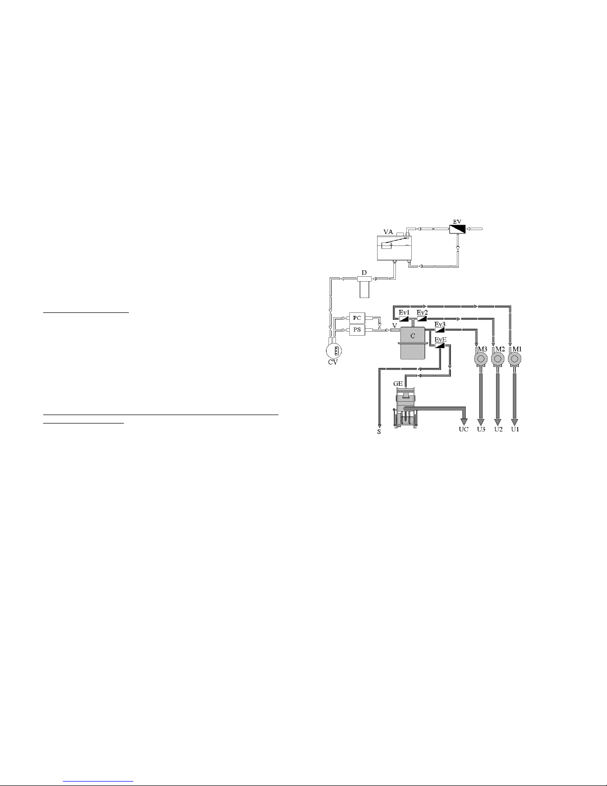
HYDRAULIC CONNECTION
INSIDE TANK
The machine is already set for the inside tank working.
WATER SYSTEM CONNECTION (OPTIONAL)
• disconnect the silicon pipe, which comes from the tank, from the limestone
filter.
• connect the silicon pipe coming from the water resevoir to the filter.
• connect the connector with the two grey wires coming from the water reser-
voir to the connector with two grey wires of the machine.
• disconnect the wires of the float and connect the black and green wires com-
ing from the water reservoir to the black and green wires into the machine.
• check that the net-system pressure doesn't overcome the 2 bars, otherwise it is
necessary to install a pressure reductor.
• Connect the water inlet tube to the inlet electrovalve with a ¾ " fitting.
Table of contents
Popular Beverage Dispenser manuals by other brands

CDS AUTOMATEN
CDS AUTOMATEN ML-16C2-C user manual

Siemens
Siemens GA 3000 OPERATING & SERVICE MANUAL

Bunn
Bunn IMIX Service & repair manual

Fizz Creations
Fizz Creations Slush Puppie Instructions for use

Cornelius
Cornelius IntelliCarb Cold Beverage Dispenser Training manual

TAPRITE
TAPRITE Rattler II Instructional manual