Labnics Equipment LF-300D User manual

Instruction Manual
ULTRA-LOW TEMPERATURE FREEZER
Model : LF-300D
Labnics Equipment
Please read this manual carefully before using the instrument

Thank You for Buying a LABNICS Freezer!
For your personal safety and better performance of the unit, please read this Instruction Manual
thoroughly and save it properly for future reference.
Failure to read, understand and follow the instructions given in this manual may result in damage
to the unit, injury to operating personnel and poor equipment performance.
The material in this manual is for information purposes only. The contents and the product it
describes are subject to change without notice. LABNICS makes no representations or
warranties with respect to this manual.
Always take precautionary measures (clothing, gloves, goggles etc.) while using the equipment.
Always dissipate extreme cold or heat and wear protective clothing.
Always follow good hygiene practices.
Each individual is responsible for his or her own safety.

Table of Content
CHAPTER CONTENT PAGE No.
1 Schematic Picture and Description 1
2 Pre-installation 2
3 Operation Direction 2
3.1 Using For the First Time 2
3.2 Adjust the Temperature 4
3.3 Function Setting 5
4 Defrost, Unused, Maintenance 6
5 Service After Sale 7
6 Technical Information 8
7 Circuit Diagram 8
8 Service Report 9

- 1 -
CHAPTER1. SCHEMATIC PICTURE AND DESCRIPTION:-
Ultra-low temperature freezer is designed to store materials under very low temperature condition for hospitals,
epidemic stations, blood banks, research institutes, universities, biological pharmaceutical industries and gene
engineering, etc. The internal temperature in cabinet can be easily adjusted through the keys on control panel. All
operations are convenient and reliable.
Knob
Control Panel
Up Cabinet
Down Cabinet

“6” “5”
- 2 -
PA
Print
Set
o
- 40.0 C
o
- 40.0 C Up
Up
Down
o
- 40.0 C
LF-300D
Enter
o
- 40.0 C Down
CHAPTER 2. PRE-INSTALLATION:-
1) How to Transport: Pick up the unit from the bottom of tank and a slant with 45° is acceptable. All
transportation should be done carefully.
CHAPTER 3. OPERATION DIRECTION:-
3.1
2) Remove all wrappers.
3) Check accessories and documents according to package list.
4) Clean the unit thoroughly before any operation.
5) Installing Location : Do not keep the unit in direct sunlight or near heating diffusers, radiators, or other
o
sources of heat. The ambient temperature should not exceed 32 C. A minimum 20cm space on the sides,
rear and top should be provided for better air circulation and heat discharge. Avoid location where there is too
much cold, high humidity and can be easily splashed by water.
Safety Introduction:-
1) Power supply : This LF-300D freezer is designed for operating under 220V/50HZ AC power supply. The unit
can normally start under the voltage varying from 198V to 242V.
2) Must provide one single exclusive plug receptacle with credible grounding to the unit.
3) Inflammable and explosive materials, as well as high corrosive acid and alkali must be strictly prohibited in
cabinet.
4) Keep the keys properly, so that the children's can't be able to open the back door which may result in
unexpected injury.
5) To avoid cold injury, please place and remove goods with protective gloves.
Function Introduction for Display Panel:-
:LCD Window: These windows display the real temperature of Up/down chambers under
normal running condition and display different hint string under set conditions:
:Function Adjustment Pads: Press these pads to show different functions combining with
different function keys.

- 3 -
“Enter”
“PA”
“Time”
Temp.Setting
“LTL”
“HTL”
“Print”
“Comp”
“High Alarm”
“Low Alarm”
“Print Port”
“Output”
“Fault”
: Press this key to activate all parameter adjustments. Under alarm status, press this key
which wills stop the alarm buzz and "Mute" displays in LCD window.
: Keyboard locking function is developed in this unit. While unlocking the keyboard, modify
the password and enter the right password. The default password is "000". The LCD
window displays under locking status and under unlocking status.
: For easy record and print of the saved temperature data, a built-in clock with YMDHM is
developed.
: Individually set the storage temperature of up and down cabinets of this unit. After adjusting
the temperature, the microcomputer control system will run automatically to maintain a
stable temperature in tank.
: When the temperature in the tank decreases below the low temperature limit (LTL) setting,
system will alarms to show warning.
: When temperature in the tank is higher than the high temperature limit (HTL) setting,
system will alarms to show warning (During the initial start-up, a "HTL" alarm is a normal
phenomenon but after stabilizing temperature "HTL" alarm will stops. Now you can keep
your goods in the freezer.)
: This unit develops a function of automatically printing the real-time temperature data and
manually printing the latest seven day's data.
: This indicator lights up when the compressor is running.
: This indicator blinks and alarms when the temperature in chamber is higher than the HTL
setting.
: This indicator blinks and alarms when the temperature in chamber is lower than the LTL
setting.
: This indicator lights when the remote port is connected successfully.
: This indicator lights up when the matched micro-printer is properly connected.
: The LCD window displays corresponding error code when this indicator lights up. The code
"E4" denotes that the ambient temperature is too high, so user should assure the ambient
o
temperature should be lower than 32 C. For other error codes please contact our service
center and remove all the products present in cabinets to avoid jeopardizing user's product
safety.
Special Notice: Functions marked with "*" are available only for some special customers or when the unit is
equipped with the optional parts.

- 4 -
3.2 Initial Start-up:-
a. Connect the power supply so that the unit immediately comes to working status.
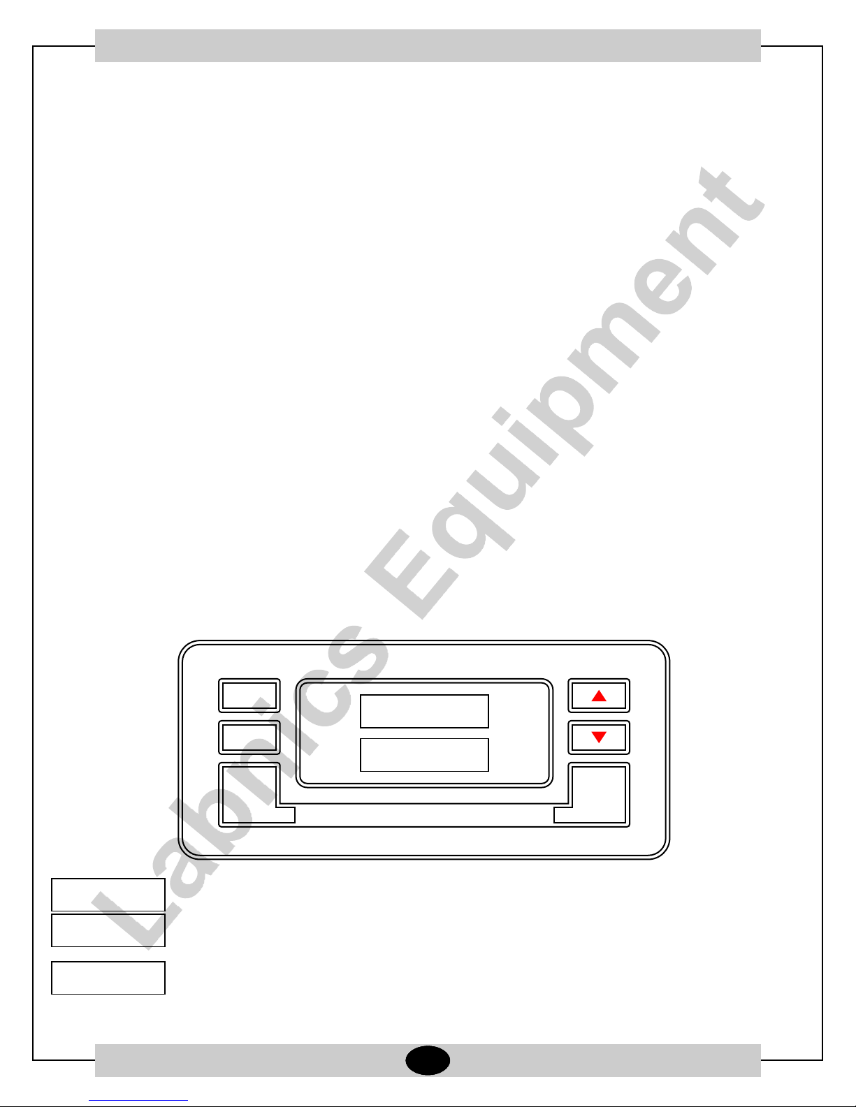
b. The initial password for locking keyboard is "0000" in factory. Before entering the password, the "set",
"6" and "5" keys are all disabled while "PA" displayed in LCD window.
c. Enter Password: Press "PA" to make the input window active. The LCD for up cabinet displays "PA"
and the LCD for down cabinet displays "000" with the mark blinking. Press "6" to change the input bit
which circularly blinks from the hundred to one bit in turn. Press the key once for one bit. Now press "5"
to enter your required number in the blinking bit, press the key to add 1 per touch to this bit which will
return to 0 after 9. After entering all three bits password, press "Enter". If the entered password is right,
LCD will stop blinking and display . Now the password is unlocked. If the wrong password is entered,
it will still keeps on lighting and blink for 6 seconds with a frequency of 2HZ. Only after releasing the
password all functions and parameter changes and setting are activated. Under unlocking status, if no
keys are pressed within 2 minutes, the system switches to locking condition.
d. Set Password: Under unlocking state press the "PA" key, so that LCD displays the current password
with the hundred bit blinking. Press "6" to change the setting bit which circularly blinks from hundred bit
to one bit in turn. Press the key once for one bit. Now press "5" to set your required number for the
blinking bit, press the key to add 1 per touch to this bit which will return to 0 after 9. When all new three
bits number is set, press "Enter" key. Then LCD stops blinking and displays the new password.
System will save your new password and 15 seconds later, the LCD returns to its normal displaying
state.
e. "Mute" : Press the "Enter" key, LCD displays "Mute" and the alarm buzzer switches to alarm locked
status. Now, the alarm buzzer will be closed under any error condition.
f. Disable "Mute": Press the "Enter" key again, the mute indicator lamp closes and the alarm buzzer
switches to open status. The buzzer may work and will stop only when the system recovers to its normal
working condition. Otherwise press the "Mute" key again to close the alarm buzzer. Then the mute
indictor lamp lights up and the buzzer come to alarm locked status.
g. Set Temperature:
Under unlocking state press the "Set" key to set different running temperatures. Press the key per
touch, the LCD displays "Temp → HTL → LTL → Time → Temp" respectively in turn. Set the
corresponding parameter when the required parameter lamp lights. If no keys have been pressed
within 15 seconds, the system exits the setting state and reverts to its normal display.
Press the "Set" key to change the system to "Temp" state and set the running temperatures for
up and down cabinets. LCD windows display the current setting value with the Ten bit of up cabinet
temperature blinking. Press "6" to change the blinking bit which changes in sequence
accordingly "Ten bit of up → One bit of up → Ten bit of up → Ten bit of down → One bit of down →
Ten bit of down → Ten bit of up". Now press "5" to add 1 per touch to the blinking bit which will
return to 0 after 9. When the setting finishes, press the "Enter" key to activate the setting. Then the
indictor lamp in temperature display window stops blinking and the mark "Temp" disappears.
Then the system exits the setting status, if no keys have been pressed within 15 seconds, system
exits the setting state without getting any data saved and reverts to its normal display.
o o
Notice : The default temperature is set as -35 C in factory. Please do not set any temperature lower than -40 C to
assure the performance and stability of unit.

- 5 -
3.3 Functions Setting:-
a) Set High Temperature Limit (HTL):-
Press the "Set" key, the system switches to "HTL" state and now you can set the alarming HTL of up
and down cabinets. LCD windows display the current setting value with the Ten bit of up cabinet
temperature blinking first. Press the "6" key to change the blinking bit which changes in sequence
accordingly "Ten bit of up → One bit of up → Ten bit of down → One bit of down → Ten bit of up". Now
press "5" to add 1 per touch to the blinking bit which will return to 0 after 9. When set finishes, press
"Enter" to activate the setting. Then the indicator lamp in temperature display window stops blinking
and the set mark "HTL" disappears. Now the system exits the HTL setting status. If no keys have been
pressed within 15 seconds, system exits the setting state without getting any data saved and reverts to
its normal display.
o o
The HTL value can be adjusted from 5 C to 10 C higher than temperature setting value and the default
o
value is 5 C.
b) Set Low Temperature Limit (LTL):-
Press "Set" key, the system switches to "LTL" state and now you can set the alarming LTL of up and
down cabinets. LCD windows display the current setting value with the Ten bit of up cabinet
temperature blinking first. Press the "6" key to change the blinking bit which changes in sequence
accordingly "Ten bit of up → One bit of up → Ten bit of down → One bit of down → Ten bit of up". Now
press "5" to add 1 per touch to the blinking bit which will return to 0 after 9. When set finishes, press
"Enter" to activate the setting. Then the indicator lamp in temperature display window stops blinking
and the set mark "LTL" disappears. Then the system exits the HTL setting status. If no keys have been
pressed within 15 seconds, system exits the setting state without getting any data saved and reverts to
its normal display.
o o
The LTL value can be adjusted from 5 C to 10 C lower than temperature setting value and the default
o
value is 5 C.
c) Time Display:-
Press "Set" key so that the system switches to "Time" state. Now set the current clock. Temperature
window displays current temperature and the Ten bit of year blinks in clock display window. Press "6"
to change the blinking bit which changes in sequence accordingly "Ten bit of year → One bit of year →
Ten bit of month → One bit of month → Ten bit of day → One bit of day → Ten bit of hour → One bit of
hour → Ten bit of min. → One bit of min. → Am or PM → Ten bit of year". All these shows in the format as:
"Y: D: AM: PM". Now press "5" to add 1 per touch to the blinking bit which will return to the minimum
after the max. When the set finishes, press "Enter" to activate the setting. Then the number in time
display window stops blinking and the set mark "TIME" disappears to exit the time setting status. . If no
keys have been pressed within 15 seconds, system exits the setting state without getting any data
saved and reverts to its normal display.
d) Set On/Off for Up/Down Cabinet
Press and hold the "Set" key for 5 seconds, the system switches to "set on/off for up and down
cabinets" and sets the on/off for up and down cabinets respectively. Now "Up off" and "Down off"
blinks in the temperature display window. Press "6" to change the running state which circularly
change in sequence accordingly to: "Up off lights & Down off blinks→ Up off blinks & Down off lights →
Up off blinks & Down off blinks → Up off lights & Down off blinks", which denote: Up off → Down off → All
on → Up off. Please set the on/off status for up/off cabinet respectively according to our need.

- 6 -
e) Auto Print:
Press the "Print" key; system switches to auto print mode. Now AUTO displays in the LCD window and
the print indicator lamp changes to normal bright state. Under this mode press the print key of printer to
automatically print the recorded data. All data are printed per 5 minutes with a format as "Year, Month,
Day, Time, and Temperature". When the print finishes, the buzzer buzzes for 5 seconds and the system
exits the print mode. To cancel print midway, press "Print" again.
f) Manual Print:
Press and hold the "Print" key for 5 seconds, the system switches to manual print mode. Now the LCD
window displays "--- -1" and the print indicator lamp blinks. Then press the print key of printer to print
the current recorded data. Press "5" key once to print the data of previous day and the LCD displays "--
-2". Similarly, the recorded data of the other days can be printed manually. All data are printed per 5
minutes in a format as "Year, Moth, Day, Time, temperature". When the print finishes, the buzzer
buzzes for 5 seconds and the system exits the print mode. To cancel print midway, press "Print" again.
Special Notice:
Functions marked with "*" are available only for some customers or when the unit is equipped with the optional
parts.
DO NOT place anything immediately after the power supply is connected. About a 6~8 hour's there should be no-
load running before storing materials is recommended.
CHAPTER 4. DEFROST, UNUSED, MAINTENANCE:-
1. There will be some frost on the surfaces of chamber for a long time running which may decrease the
performance of freezer. If the thickness of frost is more than 10mm, some defrost operations are
recommended.
2. Disconnect the power supply before defrosting. Wear special protective gloves for any interior operation.
Open the door and remove all materials from freezer. There are two ways to defrost: (I) softly spud the frost
on the surfaces with defrost shovel, (II) let the internal temperature rise naturally to thaw all frost accretion.
Then clean up the water thoroughly with dry rag.
3. Connect the power supply after defrosting is completed to run your freezer.
4. Note: Any electric heater, metal tool or edge tool CAN NOT be used during defrost operation.
5. Leave Unused: If the unit is not used for long time, please disconnect power supply and maintain as the
following procedures. For next time operation, ensure that there is not water around the liners to avoid the
seal of door is frozen.
6. Clean: Regularly clean the filter for better performance of freezer. (Procedure: Loose the two bolts in the
ventilating panel and lay the panel flatly. Then loose the sit bolts in the filter and remove the dust with soft
brush or wash it. Dry the filter before installing again.
7. Maintenance: The freezer should be cleaned regularly. For personal safety, please cut the power supply for
any maintenance! Wear special protective gloves and wipe the inward and outward walls with wet and soft
rag.
Note:DO NOT sprinkle water on the faces of cabinets, which may decrease insulating property of electric parts and
rust metal parts.
DO NOT use hot water, corrosive cleanser and organic solvent!

- 7 -
CHAPTER 5. SERVICE AFTER SALE:-
Some unexpected failures may arise during running. Please pay attention to the running status of your LF-300D
freezer. If any exceptional case arises, please check and solve it according to the following introductions. If the
problem is not solved well, please contact our service center for details.
Problem Possible Cause
ULT freezer does not operate Power outage has occurred.
The plug is not properly plugged-in.
Fuse is blown.
Voltage is too low or too high.
Compressor does not work Power in control panel is off.
Temperature setting is wrong.
Temperature is higher than setting Frost in inner wall is too thick.
The door is not closed properly or is opened too frequently.
Overfull materials are put into chamber.
Ambient temperature is too high.
Too great noise Freezer is not leveled well.
Freezer leans upon the wall.
Below are normal operations:
There are some light clashes when the compressor starts up and stops.
During rainy and watery season some frost may accumulate on the surfaces of cabinets. Please clean it with
dry rag.
DO NOT open the door twice within 5 minutes. This may lead the hot air into the interior of freezer and the
door may be difficult to open because of a negative pressure due to a sharp decrease of temperature of this
part air.

Thermometer
Compressor M1
Start Relay
M2 Cool Fan
L
N
Microcomputer
Controller
- 8 -
CHAPTER 6. TECHNICAL SPECIFICATIONS:-
Model No. LF-300D
Climatic Type N
o
Internal Temperature -10 ~ -40 C
Useful Capacity (L) 208
Rated Voltage (V) 220
Rated Frequency (HZ) 50
Input Power (W) 375
Safety Type I Class B Type
Refrigerant R404A
External Dimension (L×W×H) mm 623 x 604 x 1755
Weight (Kg) 90
Catalog No. 04590304
Package List :
Name Instruction Quality Warranty Key Defrost Plastic
Manual Certificate Card Shovel Bag
Amount 1 1 1 2 1 1
CHAPTER 7. CIRCUIT DIAGRAM:-
Power Supply
All technical parameters and circuit diagram in nameplate are final ones for your units.

Customer’s Address :
SERVICE REPORT
Contact Person / Designation :
Tel.No.:
Fax No.:
Weekly Off.:
Dept.:
Date
Nature of Problem :
Observation & Action Taken :
Customer’s Remarks :
Parts Replaced :
Parts Recommended / Action Required : Yes
Service Engineer’s Name & Signature
Requisition Number :
Customer’s Name, Signature, Date & Stamp
Page ____ Of ____
No
Model Serial No.
Date :
Status : OK
Installation
Demonstration
Maintenance
Repairs
Application
Calibration
Validation
Not OK
Warranty
Contract
Billable
Courtesy
SR. No.
System
Configuration
Time
From To
- 9 -
Table of contents
Other Labnics Equipment Freezer manuals