PAGE 5
39 01207 Button Head Allen Screw 3/8"-16UNC x 3.25" Length
40 01173 Button Head Allen Screw 3/8"-16UNC x 2.75" Length
41 01193 Button Head Allen Screw 3/8"-16UNC x 2.25" Length
42 01195 Button Head Allen Screw 3/8"-16UNC x 2.00" Length
43 01072 Button Head Allen Screw 3/8"-16UNC x 1.00" Length
44 01165 Button Head Allen Screw 3/8"-16UNC x 0.75" Length
45 01076 Button Head Allen Screw 5/16"-18UNC x 2.50" Length
46 01226 Button Head Allen Screw 5/16"-18UNC x 1.25" Length
47 01208 Flat Head Allen Screw 3/8"-16UNC x 0.75" Length
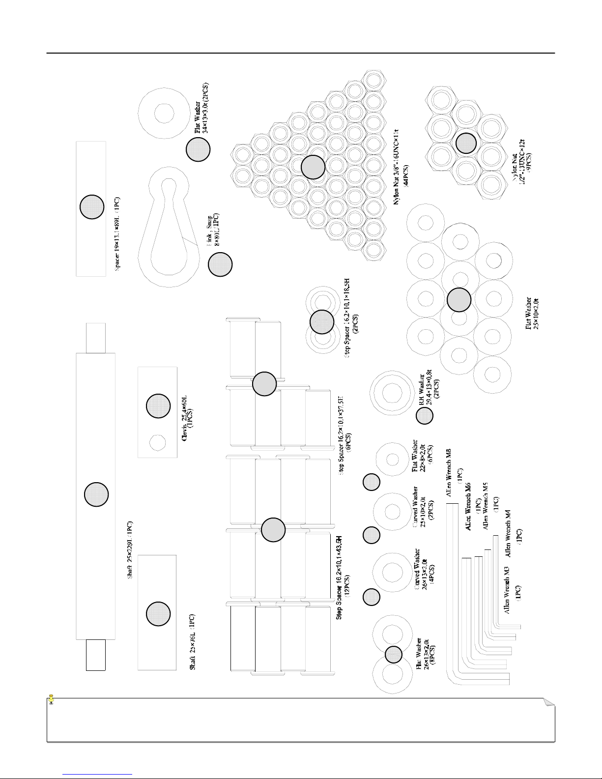
48 01209 Flat Washer 1/2" x 26mm
49 01210 Curved Washer 1/2" x 26mm
50 01211 Flat Washer 3/8" x 25mm
51 01212 Curved Washer 3/8" x 25mm
52 01213 Flat Washer 5/16" x 22mm
53 01214 Cap Mounting Ring
54 01216 Nylon Nut 1/2"-13UNC
55 01217 Nylon Nut 3/8"-16UNC
56 01087 Plastic Washer 1.125" I.D.
57 01222 Hardware Cap
58 27028 Threaded Split (Clamp) Collar
59 05094 Weight Stack / Guide Rod Bumper 2.50" dia. X 1.50"
60 03045 Roller Pad
61 03042 Seat Pad
62 03043 Upper (Small) Back Pad
63 03044 Lower (Large) Back Pad
64 01219 Pulley Spacer 16.2 x 10.1 x 43.5
65 01220 Pulley Spacer 16.2 x 10.1 x 37.5
66 01221 Pulley Spacer 16.2 x 10.1 x 18.5
67 01215 Flat Washer 34 x 13 x 3.t (Pivot Shaft)
68 25006 Weight Plate (single)
69 05097 Selector Pin (Weight Plate)
70 20006 3.5 inch dia. Cable Pulley
71 20007 4.5 inch dia. Cable Pulley
72 32006 Lat / Press Arm Cable Assembly (Length: 151.58 inches )
73 32005 AB Crunch Cable Assembly (Length: 71.38 inches)
74 32003 Low Pull / Leg Extension Cable Assembly (Length: 110.63 inches)
75 32007 Free Motion Cable Assembly (Length: 143.31 inches)
Item # Part Number Description
76 01218 Snap Link (Accessory Mounting)
2
6
4
9
2
4
2
4
2
8
4
70
2
6
2
9
44
8
2
4
2
4
1
1
1
12
6
2
2
19
1
21
2
1
1
1
1
Quantity
1
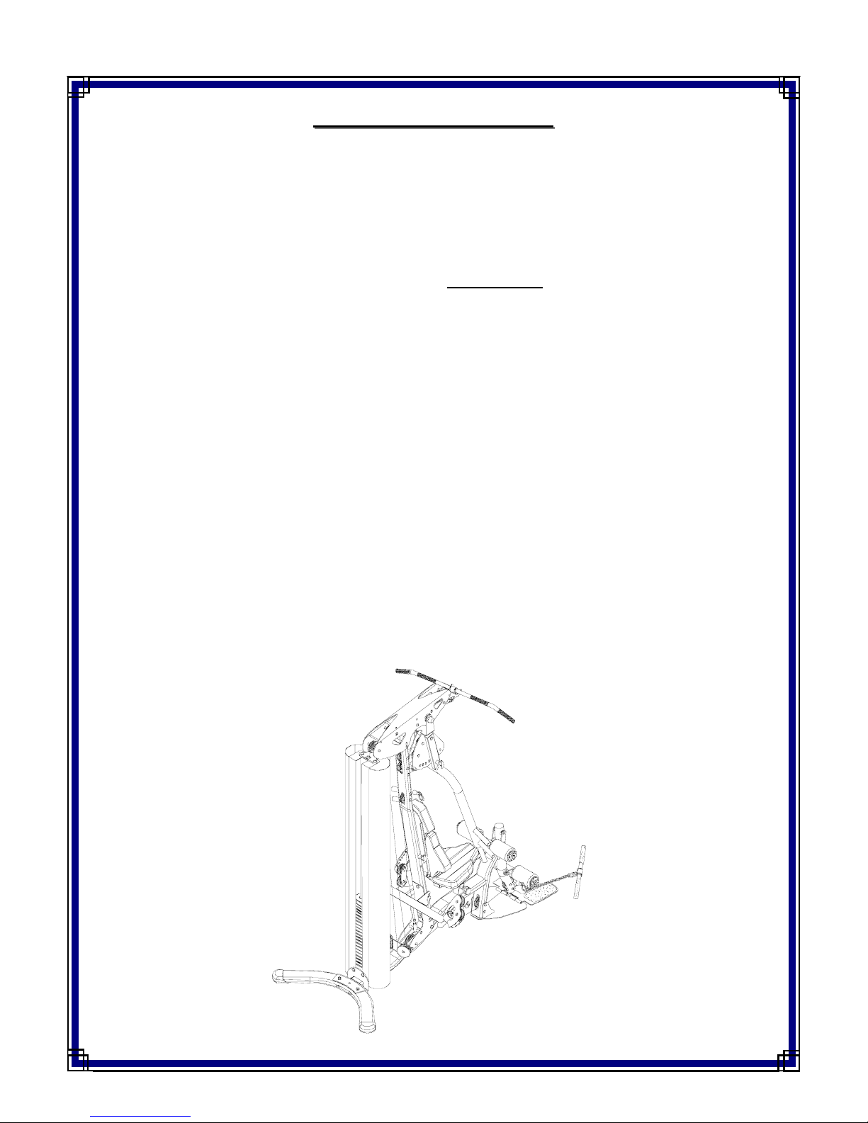
LS 70 GYM