Landis McKay Stitcher 77 Specifications

Shoe Systems Plus, Inc.
249 W Main Street
Goshen, NY 10924
1-800-354-6278
INSTRUCTIONS TO OPERATORS
LANDIS CHAINSTITCH McKAY STITCHER
Model “77”
CATALOGUE OF PARTS


MODEL “77” CHAINSTITCH
INTRODUCTION
The Landis Model “77” Chainstitch McKay Stitcher is the result of many years of experience in the
design and manufacture of shoe machinery, and has been especially designed to fit the needs of the shoe
rebuilder of today and to enable him to increase his business through the repair or resoling of ladies’ shoes.
The Model “77” McKay Stitcher is simple in design, constructed of the finest materials and manu-
factured with unusual accuracy, which is conductive to low cost of operation and low upkeep. In order to
get the benefit of the features of this Stitcher the only necessary contribution by the operator is reasonable
care in preparing and fitting up his work. If this is done in a first-class manner, excellent results will be
obtained.
When sewing on the Model “77” McKay Stitcher no anxiety need be felt on the part of the operator
should small trifles arise at times, which can be eliminated by consulting the following instructions which
will enable you to care for your machine properly and keep it in perfect adjustment. For your particular
benefit, it is desired that you familiarize yourself as much as possible with the operation of the machine.
The following instructions will be of considerable assistance towards helping you in maintaining, adjust-
ing and operating your machine. Remember that the Model “77” McKay Stitcher is a quality built ma-
chine, as are all Landis Machines. Clean it, oil it, and it will render you perfect service.
The Fayscott Landis Machine Corp. will continue to manufacture the Model “77” McKay Stitcher
as a Landis Product and we reserve the right to make changes or improvements at any time, without
thereby incurring any obligation either to install the same on machinery or equipment previously sold, or
install the old part, which has been changed, improved or omitted in new machines or equipment subse-
quently sold. Prices and equipment subject to change without notice.
FAYSCOTT LANDIS MACHINE CORP.
-1-

-2-
GENERAL INSTRUCTIONS
Keep your machine well oiled. Use a good grade of Oil. We recommend Landis Stitcher Oil.
Always use a good grade of Liquid Wax. We recommend Landis Yellow Label-Al-Liquid Wax for McKay
Stitchers.
All Model “77” McKay Stitchers are carefully adjusted at the factory by experts who are competent on these
machines, and they are shipped to you ready for operation.
All parts are of the highest grade material possible to purchase for their purpose and are inspected to insure
interchangeability so that all repair parts fit into place without fitting or difficulty.
How To Order Parts for Quick Delivery
1. Give the complete part number of the part needed and quantity.
2. Give the Model and Serial Number of your machine.
3. Write your name and address as plainly as possible.
4. Prices of parts do not include postage or insurance. This is extra. Parts are usually
shipped parcel post insured.
5. Prices are subject to change without notice.
NOTE: When mailing parts to Factory - be sure to write your name and address plainly
on the package. Also write your name and address on your letter explaining why goods
are being sent to the factory.
SETTING UP MACHINE
After the Model “77” McKay Stitcher is uncrated and placed in position where it will be used, place
motor extension cord plug in electric light socket and machine will be ready to operate.
Machines are carefully oiled before leaving the factory, but should also be oiled carefully before operating.

THREADING THE WAX POT AND HORN
Put spool of thread on Thread Holder. Put Thread
up through first hold in Thread Unwinder Rod and
wrap thread half way around Rod and up through
second hole in rear of Thread Unwinder Rod. Bring
Thread up through Horn Spindle, by using the long
straight Thread Hook furnished. To do this remove
Wax Pot and push Thread Hook down in small hole
found below the Wax Pot to the bottom of Horn
Spindle, loop Thread around barb of Thread Hook
and pull up through hole, then replace the Wax Pot.
Place Thread in Tension and over Thread Roll to Wax
Pot, down through Lower Wax Pot Roll, then up
through Wax Pot Stripper, through Thread Guide
Pin and under Horn Thread Roll and up Horn to
small hole in Whirl. A small curved Thread Hook
will be found in the supply package. (See Figure
No. 1).
LIQUID WAX - CLEANING WAX POT
Stir Liquid Wax thoroughly before putting it in Wax
Pot. Use “thinner” to thin wax when too thick or
heavy. Order Landis Yellow Label Machine Cleaner
& Wax Thinner available in pint and quart cans.
CAUTION: Do not put oil in wax pot.
Remove Wax Pot at least once a week and clean thor-
oughly with kerosene or coal oil. Keep thread rolls
free from old or dried wax. (See Figure No. 1).
SIZE OF THREAD AND NEEDLE
In general practice a No. 33 Needle and 4 Cord right
twist Thread will usually be found satisfactory.
Figure 1
S-531
LANDIS “77”
-3-

LANDIS “77”
TO SET NEEDLE
Turn machine until Needle Bar is at its lowest position. Adjust needle
until it projects slightly below bottom of whirl. The Needle should be set
so that the Whirl lays the thread in the barb groove of the Needle as it
revolves around the Needle, much on the order of the Looper on the
Curved Needle Stitcher. (See figure No. 2).
PLACING THE FEED POINT
Place Feed Point S-191 so that it extends 3/64” below bottom of
Presser Foot S-130 when Feed Socket S-190 is at its lowest point.
(See figure No. 3).
NEEDLE BAR FRICTION
For more friction, turn Adjusting Screw (in top of Main Head) to the right; for less friction, turn screw left.
This Friction Screw is adjusted at the factory and requires little attention. It is used to hold Needle Bar in
place when Latch is released. A few drops of oil should be placed in Oil Hole each day.
CAST-OFF FRICTION
The Cast-Off Friction is adjusted at the factory so the Cast-Off Block can be moved up and down with the
fingers without moving the Cast-Off Rod. For more friction, turn Adjusting Screw in Cast-Off Friction
Holder to right; for less friction, turn Screw to left. A few drops of oil should be placed in Oil Hole each
day.
Figure No. 3
S-130
S-190
S-191
Figure No. 2
-4-

LANDIS “77”
-5-
SETTING THE CAST-OFF
The adjustment of the Cast-Off S-95 is important. The Cast-Off Point
must be set low enough to completely cover the barb of the Needle S-
92 as the Needle pulls the thread up.
To adjust Cast-Off up or down, loosen Cast-Off Screw S-97, raising or
lowering the Cast-Off to the desired position, and afterward tighten-
ing the screw. (See figure 4).
The correct relation of the Cast-Off to the Needle is that it just clears
the side of the Needle. To test this relation, raise and lower the Cast-
Off repeatedly by lifting on Cast-Off Block, S-96. If too close, the
Cast-Off will spring the Needle sideways. To correct this, spring the
Cast-Off a little away from the Needle. Pliers will be found in the
supply package for this purpose. Should the Cast-Off be too far from
the Needle, remove the Needle, spring the Cast-Off in as much as nec-
essary.
TO REMOVE AND REPLACE CAST-OFF: Loosen Cast-Off Set Screw
(S-97). Loosen and take off Needle Clamp Collar S-93, remove Cast-
Off. To replace Cast-Off, insert Cast-Off in Cast-Off Block, tighten
Set Screw and replace Needle Clamp Collar. (See figure No. 4).
ADJUSTMENTS FOR ELIMINATING THE SKIPPING OF STITCHES
See that the following are in proper adjustment:
Timing of Whirl (See Page 8)
Setting of Needle (See Page 4)
Setting of Cast-Off (See Page 5)
LENGTH OF STITCH - ADJUSTMENT OF FEED
The usual practice is to use about 4-3/4 stitches per inch. Should
you desire to sew more or less stitches per inch, loosen the Hexa-
gon Screw S-260 on Feed Cam S-255. Turn Adjusting Screw S-
259 on Movable Cam S-256 in for more stitches per inch and
out for less stitches per inch. After adjustment is made, press
Movable Cam and Feed Cam together and tighten Hexagon
Screw. (See figure No. 5).
Figure No. 4
S-93
S-95
S-92
S-97
S-96
Figure No. 5
S-256
S-259
S-255
S-260

-6-
CAUTION:
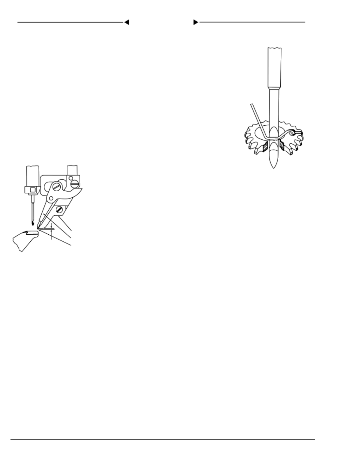
Before mounting the sole on a shoe, it will be well to find and pull out two to four staples, which will
be found near the beginning of the toe curvature, where the upper puckers worst. These staples were put
in to hold the sole before the first McKay sewing. These staples will interfere with sewing and may even
break the needle. They are generally a little outside the row of lasting tacks.
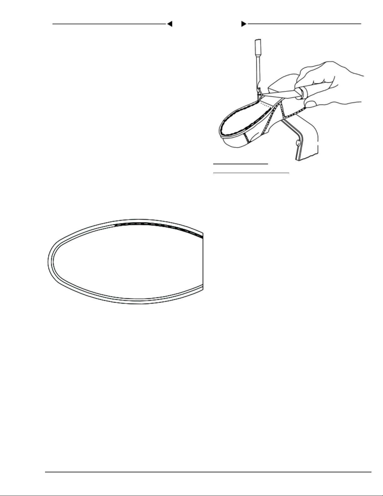
STITCHING SHOES
Shoes are stitched in the same order as on your other stitching machine; that is to say, the shoe is
put on the horn with the heel to the left and the stitches started in the shank, stitching up and around the
toe, turning the heel of the shoe from left to right, with the heel towards the operator, then sewing down the
opposite side of the shoe to the shank with the heel on the right. You will find this procedure extremely
easy.
With the different types of shoes, namely Welt, McKay and Turn, it will be found necessary to stitch
at different distances from the edges of the inner sole.
On McKays, the usual practice is to stitch along the old line of stitching if the make-up of the shoe
enables the line of stitching to catch the upper.
In stitching the Turn shoe, it is desirable to stitch outside of the inside channel of the turn shoe in
order to catch the upper.
In stitching the Welt shoe, it is desirable to stitch as close to the edge of the inner sole as the Horn
will permit. The same applies to the stitching of cement shoes.
It might be well to mention the fact that often on McKay shoes the uppers are not drawn or lasted as
close to the shank as they should be, in which case it would be good practice to sew a little outside the
regular line of stitching to catch the upper.
NOTE: With the channel cut the proper distance from the edge, this difference of stitching from
the edge of the inner sole can be accomplished by simply tipping the shoe up in back or down in front, as
the case may require, much on the order of the Straight Needle Stitcher. The tipping of the shoe has the
desired effect of setting the stitches in on the insole or out as may be desired.
Ordinarily the stitching is accomplished by simply holding the shoe in its place on the horn and
the presser foot in the groove, letting the machine feed the shoe around.
LANDIS “77”

LANDIS “77”
-7-
As for sewing the channel, and the general
handling of stitching, you will find the Model
“77” McKay Stitcher without doubt the easi-
est simplest machine to operate and you will
find it extremely so in sewing in the channel
and around the toe. There is such a marked
difference between this and other machines
that it is quite noticeable.
After stitching, cut the front thread of the
needle loop, the thread nearest you, close to
the work, raise the presser foot and remove
the shoe. (See figure No. 6). Cut Outer Thread
When Sewing Is Finished
Figure No. 6
ALOFT WORK
ALOFT STITCHING is easily accomplished with
the Aloft Channel Groover which is easy to oper-
ate, the channel operation requiring but a second
or two, and when properly done, it permits of
practically closing the grooved channel over the
thread. (See figure No. 7).
The Aloft Presser Foot should be inserted when
stitching aloft. This Presser Foot can be used for
any other type of channel work. You will find aloft
stitching extremely simple.
THREAD
It is highly important that a good grade of right twist thread be used, and should you experience difficulty
in breaking thread, examine and test your thread.
SIZES OF THREAD AND NEEDLES
For all ordinary purposes, it has been found that No. 33 needle and 4 cord right twist thread is very
satisfactory. Should it be desired to use a different size needle and thread, the chart below will show the
sizes of needles to be used with different sizes of thread.
We recommend needles and right twist thread as follows:
NEEDLE SIZES 33 34 35 36
THREAD USED WITH 4 cord 5 cord 6 cord 7 cord

LANDIS “77”
-8-
THREAD TENSION
To increase the Tension, turn Tension Thumb Nut S-583 to the right,
and to decrease, turn to the left. (See figure No. 8).
WAX STRIPPER ADJUSTMENT
To replace Wax Stripper S-573, remove
Stripper Screw S-574 and take out old
Stripper, insert new Stripper and replace
Stripper Screw. (See figure No. 9).
CAUTION: Do not tighten rubber stripper too tight as this tends to increase tension.
TO REMOVE WHIRL
Remove the Horn Cap S-503 by taking out two Fas-
tening Screws, S-504 and S-505, so that the Horn Tip
S-502 can be raised enough to allow removal of Whirl.
(See figure No. 10).
TO REPLACE AND TIME WHIRL
Care must be taken to see that the Whirl S-507 is cor-
rectly timed. Two settings of the machine are neces-
sary. 1st - Revolve the machine by hand until the ar-
row on the Feed Cam S-255 coincides with the Arrow
on the Main Head (See figure No. 5). 2nd - Set the
Horn at the left until the marks on the Horn and Horn
Table coincide. (See figure No. 11).
With these settings arranged, insert the Whirl so that
the small hole in Whirl coincides with mark on Horn
Tip (See figure No. 10). Push the Horn Tip down,
replace Horn Cap and fasten securely with two Screws.
Set Horn So That Lines Meet
Figure No. 11
S-503
S-504
S-505 S-507
S-502
Set thread hole in whirl in line with
mark on horn tip. The outer edge of
pinion tooth in mesh, is even with
top of whirl.
Figure No. 10
Thread
S-574
S-573
Figure No. 9
For More
Tension
Turn
For Less
Tension
Turn
S-583
Thread
Figure No. 8

LANDIS “77”
-9-
TO CHANGE PINION
Take out the two Fastening Screws S-504 and S-505, remove Horn
Tip S-502 and Horn Cap S-503; the Pinion S-508 may now be
lifted out and replaced with a new one.
Be sure that the new Pinion meshes with the Whirl S-507 prop-
erly. (See cut for Pinion Adjustment).
Replace the Horn Tip and Whirl. Be sure Whirl is correctly
timed as previously described. Replace Horn Cap and fasten
with two Screws. (See figure No. 12).
ADJUSTING PINION
To adjust Pinion S-508, remove Horn Rear Curved Plate S-555,
which will permit access to Pinion Adjusting Screw S-510.
To raise Pinion turn Adjusting Screw to the right; to lower Pin-
ion, turn Adjusting Screw to the left. Pinion and Whirl teeth
should mesh, and turn freely. (See figure No. 13).
HORN CAP
The top of the Horn Cap should be kept smooth at all times, also
the hole should be dressed out smooth with emery cloth if at any
time it is nicked or burred.
If not perfectly smooth, the thread may catch on sharp edges and
strand. (See figure No. 12).
ALIGNMENT OF HORN
The Horn is lined up at the factory. Should the occasion arise at
any time for re-alignment, it can be accomplished by the following
procedure:
Loosen four Screws S-531 under Horn Table slightly, which will
permit tapping the Horn to correct alignment. Tap into a central
position so that hole in Horn Cap runs true. After firmly tighten-
ing Horn Holding Screws, you can check the position by putting
needle down into the Whirl and see that it does not rub on the side
of the hole in Whirl. (See figure No. 14).
CLEANING HORN
IMPORTANT: Take off Horn Cap S-503 each day after you are
finished sewing and clean Whirl, Pinion and Rollers with kero-
sene. Your machine will be ready for work the next day and this
will eliminate any difficulty from hard and gummed wax.
On the LANDIS McKay Stitcher Model “77” the Horn is sepa-
rated in three parts to provide easy cleaning and threading.
S-503
S-507
S-502
S-504
S-505
Keep smooth at all times
S-508
S-501
TOP OF
HORN Figure No. 12
When Horn is Centrally
Located, the Whirl Will
Not Rub Needle
Figure No. 14
Horn S-501
Hole for Screw
S-556
Hole for Cover Plate
S-555 in Back of Horn
To Adjust Pinion S-508 Up,
Turn Screw S-510 to Right
To Adjust Pinion S-508 Down,
Turn Screw S-510 to Left
Figure No. 13

-10-
S-21 S-320
S-22
S-26 S-32
S-256
S-25
S-630
S-260 S-255 S-259
S-307 S-301
S-305 S-174
S-318
S-326
S-327
S-642 S-644 S-314
S-313 S-306 S-302 S-308
S-45
S-44
S-79
S-40 S-41
S-48
S-36
S-37
S-42 S-62
S-64 S-65
S-61
S-60
S-70 S-71
S-128
S-150
S-63
S-38
S-77
S-117
S-172 S-152 S-151 S-166
S-140
S-139
S-136
S-137
S-160
S-170
S-171
S-39
S-76
S-75
S-85
S-84
S-104
S-105
S-82
S-81
S-86
S-93
S-94
S-97
S-99
S-109
S-96
S-116
S-97
S-198
S-199
S-186
S-130 S-131
S-188 S-141
S-205
S-206
S-192
S-191
S-190
S-205
S-202
S-196
S-197
S-95
S-98

-11-
S-363
S-361
S-365
S-366
S-347 S-346
S-347
S-342
S-343
S-341
S-357 S-354 S-345
S-227S-226
S-181
S-175
S-176S-177
S-179
S-228
S-222
S-230
S-221
S-220
S-239
S-247
S-246
S-242 S-250
S-146 S-155
S-214
S-215
S-395
S-397
S-386
S-380
S-385 S-391
S-390

-12-
S-566 S-574
S-571 S-578
S-582
S-583
S-560
S-572 S-575
S-627
S-630
S-632
S-631
S-633
S-639
S-638
S-534
S-556
S-564
S-518
S-513 S-545 S-504
S-508 S-507
S-710
S-726
S-725
S-10
S-11
S-13
S-12
S-415
S-692
S-736
S-727
S-728
S-732

77-S-1 1 Main Head
77-S-2 1 Main Head Fastening Screw (Short)
77-S-2A 2 Main Head Fastening Screw (Long)
77-S-3 3 Main Head Fastening Screw Washer
77-S-5 1 Main Head Rear Cover
77-S-6 1 Main Head Rear Cover Screw
77-S-7 1 Main Head Rear Cover Lock Washer
77-S-10 1 Main Head Front Cover
77-S-11 1 Main Head Front Cover Fulcrum
77-S-12 1 Main Head Front Cover Set Screw
77-S-13 1 Main Head Front Cover Spring
77-S-21 1 Cam Shaft
77-S-22 4 Cam Shaft Key
77-S-23 4 Cam Set Screw
77-S-24 2 Needle Bar Driving Cam Set Screw
77-S-25 1 Miter Gear
77-S-25A 2 Miter Gear Set Screw
77-S-26 1 Hand Wheel
77-S-27 1 Hand Wheel Set Screw
77-S-29 1 Needle Bar Driving Cam Assembly,
Includes 77-S-30 and 77-S-31
77-S-30 1 Needle Bar Driving Cam
77-S-31 1 Needle Bar Driving Stud
77-S-32 1 Needle Bar Driving Cam Roll
77-S-36 1 Needle Bar Cam
77-S-37 1 Needle Bar Cam Post
77-S-38 1 Needle Bar Cam Post Screw
77-S-39 1 Needle Bar Cam Bumper Washer
77-S-40 1 Needle Bar Latch Holder Assembly,
Includes 77-S-43, 77-S-46 and 77-S-50
77-S-41-1 1 Needle Bar Latch
77-S-41A 1 Needle Bar Latch Pin
77-S-42 1 Needle Bar Latch Spring
77-S-43 1 Needle Bar Latch Holder
77-S-44 1 Needle Bar Latch Holder Set Screw
77-S-45 1 Needle Bar Latch Holder Nut
77-S-46 1 Needle Bar Latch Stud
77-S-47 1 Needle Bar Latch Spring Pin
77-S-48 1 Needle Bar Latch Stud Collar
77-S-49 2 Needle Bar Latch Stud Collar Set Screw
77-S-50 1 Needle Bar Latch Stud Taper Pin
77-S-60 1 Thread Measure Cam
77-S-61 1 Thread Measure Cam Set Screw
77-S-62 1 Thread Measure Cam Stud
77-S-63 1 Thread Measure Cam Block
77-S-64 1 Thread Measure Cam Spring
77-S-65 2 Thread Measure Cam Spring Screw
77-S-66 2 Thread Measure Cam Block Set Screw
77-S-68 1 Thread Measure Presser Bar Block
77-S-69 1 Thread Measure Presser Bar Dowel
77-S-70 1 Thread Measure Presser Bar Adjusting
Screw
77-S-71 1 Thread Measure Presser Bar Nut
77-S-75 1 Needle Bar Friction Spring
77-S-76 1 Needle Bar Friction Fibre
77-S-77 1 Needle Bar Friction Screw
77-S-79 1 Needle Bar, assembled
77-S-81 1 Needle Bar Guide
77-S-82 1 Needle Bar Guide Post Clamp Screw
77-S-83 1 Needle Bar Guide Dowel
77-S-84 1 Needle Bar Guide Stop Screw
77-S-85 1 Needle Bar Guide Stop Nut
77-S-86 1 Needle Bar Guide Post
77-S-87 1 Needle Bar Guide Post Nut
77-S-88 1 Needle Bar Guide Post Lock Washer
77-S-93 1 Needle Clamp Collar
77-S-94 1 Needle Clamp Collar Screw
77-S-95 1 Cast Off
77-S-96 1 Cast Off Holder
77-S-97 1 Cast Off Holder Set Screw
77-S-98 1 Cast Off Spring
77-S-99 1 Cast Off Spring Screw
77-S-104 1 Cast Off Guide
77-S-105 1 Cast Off Guide Clamp Screw
77-S-106 1 Cast Off Guide Pin
77-S-109 1 Cast Off Rod Assembly, Includes77-S-99,
77-S-110, 77-S-111 and 77-S-112
LIST OF PARTS - MODEL “77” MCKAY STITCHER
-13-
77-S-110 1 Cast Off Rod
77-S-111 3 Cast Off Rod Collar
77-S-112 2 Cast Off Rod Collar Pin
77-S-116 1 Cast Off Friction Holder
77-S-117 1 Cast Off Friction Holder Gib Screw
77-S-118 1 Cast Off Friction Spring
77-S-119 1 Cast Off Friction Fibre
77-S-120 1 Cast Off Friction Screw
77-S-128 1 Presser Bar Assembly,
Includes 77-S-68, 77-S-69 and 77-S-129
77-S-129 1 Presser Bar
77-S-130 1 Presser Foot
77-S-130B 1 Two Prong Presser Foot
77-S-131 1 Presser Foot Screw
77-S-133 1 Presser Bar Holder
77-S-134 1 Presser Bar Holder Pin
77-S-136 1 Presser Bar Guide
77-S-137 1 Presser Bar Guide Clamp Screw
77-S-138 1 Presser Bar Guide Dowel
77-S-139 1 Presser Bar Guide Stop Screw
77-S-140 1 Presser Bar Guide Stop Nut
77-S-141 1 Presser Bar Guide Post
77-S-142 1 Presser Bar Guide Post Nut
77-S-143 1 Presser Bar Guide Post Lock Washer
77-S-146 1 Lift Lever
77-S-147 1 Lift Lever Screw
77-S-150 1 Presser Bar Spring
77-S-151 2 Presser Bar Spring Collar
77-S-152 2 Presser Bar Spring Collar Set Screw
77-S-154 1 Lift Lever Rod
77-S-154A 1 Lift Lever Rod Retaining Pin
77-S-155 4 Lift Lever Rod Nut
77-S-156 2 Lift Lever Rod Washer
77-S-157 1 Lift Lever Rod Stud
77-S-158 1 Lift Lever Rod Stud Lock Washer
77-S-159 1 Lift Lever Rod Stud Nut
77-S-160 1 Lifting Dog Assembly,
Includes 77-S-161, 77-S-162
and 77-S-163
77-S-161 1 Presser Foot Lifting Dog Block
77-S-162 1 Presser Foot Lifting Dog Tail
77-S-163 1 Presser Foot Lifting Dog
Fulcrum Pin
77-S-164 1 Presser Foot Lifting Dog Block
Spring
77-S-165 2 Presser Foot Lifting Dog Block
Spring Screw
77-S-166 1 Presser Foot Lifting Dog Spring
77-S-170 1 Lifting Dog Trip Pin
77-S-171 1 Lifting Dog Trip Pin Set Screw
77-S-172 1 Lifting Dog Trip Pin Set Screw Rod
77-S-174 1 Presser Foot Lift Cam
77-S-175 1 Presser Foot Lifting Lever
77-S-176 1 Presser Foot Lifting Lever Adjusting
Screw
77-S-177 1 Presser Foot Lifting Lever Adjusting
Screw Nut
77-S-178 1 Presser Foot Lifting Lever Spring Pin
77-S-179 1 Presser Foot Lifting Lever Cam Roll
77-S-180 1 Presser Foot Lifting Lever Cam Stud
77-S-181 1 Presser Foot Lifting Lever Cam Nut
77-S-186 1 Feed Socket Cam Block
77-S-187 2 Feed Socket Cam Block Dowel
77-S-188 1 Feed Socket Cam Block Fastening
Screw
77-S-190 1 Feed Socket
77-S-191 1 Feed Point (Regular)
77-S-191A 1 Feed Point (Aloft)
77-S-192 1 Feed Point Screw
77-S-196 1 Feed Socket Collar
77-S-197 1 Feed Socket Collar Set Screw
77-S-198 1 Feed Socket Spring
77-S-199 1 Feed Socket Spring Fastening Screw
77-S-202 1 Feed Socket Cam Plate
77-S-205 1 Feed Socket Cam Plate Dowel Screw
77-S-206 1 Feed Socket Cam Plate Dowel
77-S-214 1 Feed Lever Connecting Link
REQ’DREQ’D
REQ’DREQ’D
REQ’D
PP
PP
PARAR
ARAR
ARTT
TT
T
NO.NO.
NO.NO.
NO. NAME OF PNAME OF P
NAME OF PNAME OF P
NAME OF PARAR
ARAR
ARTT
TT
T
REQ’DREQ’D
REQ’DREQ’D
REQ’D
PP
PP
PARAR
ARAR
ARTT
TT
T
NO.NO.
NO.NO.
NO. NAME OF PNAME OF P
NAME OF PNAME OF P
NAME OF PARAR
ARAR
ARTT
TT
T

LIST OF PARTS - MODEL “77” MCKAY STITCHER
-14-
77-S-215 1 Feed Lever Connecting Link Stud
77-S-220 1 Feed Lever
77-S-221 1 Feed Lever Clamp Screw
77-S-222 1 Feed Lever Set Screw
77-S-223 1 Feed Lever Dowel
77-S-226 1 Feed Lever Spring
77-S-227 1 Feed Lever Spring Collar
77-S-228 1 Feed Lever Spring Collar Set Screw
77-S-229 1 Feed Lever Shaft
77-S-230 1 Feed Lever Shaft Bushing
77-S-231 2 Feed Lever Shaft Bushing Clamp
77-S-231A 2 Adjusting Bushing for Feed Lever Shaft
Bush. Clamp Screw
77-S-239 1 Feed Cam Lever Assembly, Includes
77-S-229, 77-S-240 and 77-S-241
77-S-240 1 Feed Cam Lever
77-S-241 1 Feed Cam Lever Dowel Pin
77-S-242 1 Feed Cam Lever Cam Roll
77-S-243 1 Feed Cam Lever Cam Stud
77-S-244 1 Feed Cam Lever Cam Stud Nut
77-S-246 1 Feed Cam Lever Oil Wiper
77-S-247 1 Feed Cam Lever Oil Wiper Plate
77-S-248 1 Feed Cam Lever Oil Wiper Screw
77-S-249 1 Feed Cam Lever Oil Wiper Nut
77-S-250 1 Feed Cam Lever Oil Wiper Fastening
Screw
77-S-255 1 Feed Cam
77-S-256 1 Feed Cam Plate Assembly, Includes
77-S-257 and 77-S-258
77-S-257 1 Feed Cam Plate
77-S-258 1 Feed Cam Plate Block
77-S-259 1 Feed Cam Plate Adjusting Screw
77-S-260 1 Feed Cam Plate Clamp Screw
77-S-261 1 Feed Cam Plate Dowel
77-S-301 1 Clutch Sleeve
77-S-302 2 Clutch Sleeve Set Screw
77-S-304 1 Clutch Sleeve Plunger Pin
77-S-305 1 Clutch Sleeve Stop
77-S-306 1 Clutch Sleeve Plunger
77-S-307 1 Clutch Sleeve Plunger Pin
77-S-308 1 Clutch Sleeve Plunger Spring
77-S-311 1 Clutch Sleeve Plunger Fibre Stop
77-S-312 1 Clutch Sleeve Plunger Stop Stud
77-S-313 1 Clutch Sleeve Plunger Stop Bar
77-S-314 1 Clutch Sleeve Plunger Stop Bar Screw
77-S-318 1 Clutch Pulley Assembly, Includes 77-S-319,
77-S-320, 77-S-321, 77-S-322, 77-S-323,
77-S-324, 77-S-325, 77-S-326 and 77-S-327
77-S-319 1 Clutch Pulley (10 1/2” Diam.)
77-S-320 2 Clutch Pulley Driving Dog
77-S-321 1 Clutch Pulley Pipe Plug
77-S-322 1 Clutch Pulley Plate
77-S-323 1 Clutch Pulley Plate Gasket
77-S-324 4 Clutch Pulley Plate Screw
77-S-325 4 Clutch Pulley Wool Yarn
77-S-326 1 Clutch Pulley Set Collar
77-S-326A 1 Hand Wheel Set Collar (Regular)
77-S-326B 1 Hand Wheel Set Collar (For Repairs)
77-S-327 2 Clutch Pulley Set Collar Set Screw
77-S-327A 2 Hand Wheel Set Collar Set Screw (Regular)
77-S-327B 2 Hand Wheel Set Collar Retaining Screw
(For Repairs)
77-S-336 1 Clutch Pulley Round Belt
77-S-337 1 Motor Belt
77-S-340 1 Clutch Throw Out Lever Assembly,
Includes 77-S-341, 77-S-342, 77-S-343,
77-S-344, 77-S-345, 77-S-346, 77-S-347 and
77-S-348
77-S-341 1 Clutch Throw Out Lever
77-S-342 1 Clutch Throw Out Lever Wedge
77-S-343 1 Clutch Throw Out Lever Wedge Screw
77-S-344 1 Clutch Throw Out Lever Wedge Dowel
77-S-345 1 Clutch Throw Out Lever Bumper
77-S-346 1 Clutch Throw Out Lever Plate
77-S-347 1 Clutch Throw Out Lever Plate Screw
77-S-348 1 Clutch Throw Out Lever Plate Lock
Washer
77-S-354 1 Clutch Throw Out Lever Shaft
77-S-355 1 Clutch Throw Out Lever Shaft Set
Screw
77-S-356 1 Clutch Throw Out Lever Shaft Collar
77-S-357 1 Clutch Throw Out Lever Shaft Collar
Set Screw
77-S-360 1 Clutch Idler Pulley Assembly,
Includes 77-S-361 and 77-S-362
77-S-361 1 Clutch Idler Pulley
77-S-362 1 Clutch Idler Pulley Needle Bearing
77-S-363 1 Clutch Idler Pulley Screw
77-S-364 1 Clutch Idler Pulley Screw Nut
77-S-365 1 Clutch Idler Pulley Lever
77-S-365A 1 Clutch Idler Pulley Screw Nut Lock
Washer
77-S-366 1 Clutch Idler Pulley Lever Spring
77-S-380 1 Lower Clutch Pulley Assembly,
Includes 77-S-381, 77-S-382,
77-S-383 and 77-S-387
77-S-381 1 Lower Clutch Pulley
77-S-382 1 Lower Clutch Stationary “V” Pulley
77-S-383 3 Lower Clutch Stationary Pulley Screw
77-S-384 1 Lower Clutch Sliding “V” Pulley
77-S-385 1 Lower Clutch Pulley Key
77-S-386 2 Lower Clutch Pulley Fibre Washer
77-S-387 3 Lower Clutch Stationary Pulley Screw
Lock Washer
77-S-390 1 Lower Clutch Yoke
77-S-390A 1 Lower Clutch Yoke Spacing Washer
(1/8”)
77-S-390B 1 Lower Clutch Yoke Spacing Washer
(3/16”)
77-S-390C 1 Lower Clutch Yoke Set Collar
77-S-390D 2 Lower Clutch Yoke Set Collar Set
Screw
77-S-391 1 Lower Clutch Yoke Adjusting Screw
77-S-392 3 Lower Clutch Yoke Adjusting Screw
Nut
77-S-394 2 Lower Clutch Yoke Bracket Lock
Washer
77-S-395 1 Lower Clutch Yoke Bracket
77-S-396 2 Lower Clutch Yoke Bracket Fastening
Screw
77-S-397A 1 Lower Clutch Yoke Shaft (New Style)
77-S-398 1 Lower Clutch Yoke Shaft Set Screw
77-S-404 1 Lower Clutch Yoke Finger
77-S-405 1 Lower Clutch Yoke Finger Set Screw
77-S-409 1 Lower Clutch Shaft
77-S-410 1 Lower Clutch Shaft Oil Cup
77-S-411 1 Lower Clutch Shaft Oil Wick
77-S-412 1 Lower Clutch Shaft Set Screw
77-S-415 1 Lower Clutch Belt Guard
77-S-416 2 Lower Clutch Belt Guard Set Screw
77-S-501 1 Horn
77-S-502 1 Horn Tip
77-S-503 1 Horn Tip Cap
77-S-504 1 Horn Tip Cap Upper Screw
77-S-505 1 Horn Tip Cap Lower Screw
77-S-506 1 Horn Tip Cap Lower Screw Insert
77-S-507 1 Horn Whirl
77-S-508 1 Horn Pinion Shaft
77-S-509 1 Horn Pinion Shaft Sleeve
77-S-510 1 Horn Pinion Shaft Adjusting Screw
77-S-511 1 Horn Pinion Shaft Bushing
77-S-512 2 Horn Hollow Hex Set Screw (Lower
Shaft)
77-S-512A 1 Horn Hollow Hex Set Screw (Pinion
Shaft)
77-S-513 1 Horn Pinion Shaft Sleeve Assembly,
Includes 77-S-509, 77-S-510, 77-S-511,
77-S-514 and 77-S-515
REQ’DREQ’D
REQ’DREQ’D
REQ’D
PP
PP
PARAR
ARAR
ARTT
TT
T
NO.NO.
NO.NO.
NO. NAME OF PNAME OF P
NAME OF PNAME OF P
NAME OF PARAR
ARAR
ARTT
TT
T
REQ’DREQ’D
REQ’DREQ’D
REQ’D
PP
PP
PARAR
ARAR
ARTT
TT
T
NO.NO.
NO.NO.
NO. NAME OF PNAME OF P
NAME OF PNAME OF P
NAME OF PARAR
ARAR
ARTT
TT
T

LIST OF PARTS - MODEL “77” MCKAY STITCHER
-15-
77-S-514 1 Horn Center Bevel Gear
77-S-515 2 Horn Center Bevel Gear Taper Pin
77-S-518 1 Horn Lower Shaft Assembly, Includes
77-S-514, 77-S-515, 77-S-519, 77-S-520
and 77-S-521
77-S-519 1 Horn Lower Shaft
77-S-520 2 Horn Lower Shaft Bushing
77-S-521 1 Horn Lower Shaft Bevel Gear
77-S-530 3 Horn Spring Oiler
77-S-531 4 Horn Fastening Screw
77-S-532 1 Horn Thread Guard Plate
77-S-533 1 Horn Thread Roll
77-S-534 1 Horn Thread Roll Pin
77-S-535 1 Horn Thread Guide Pin
77-S-537 1 Horn Spindle Bearing Oiler
77-S-545 1 Horn Front Cover Assembly, Includes
77-S-546, 77-S-547, 77-S-549, 77-S-550,
77-S-551 and 77-S-552
77-S-546 1 Horn Front Cover
77-S-547 2 Horn Front Cover Pin
77-S-549 1 Horn Front Cover Knob
77-S-550 1 Horn Front Cover Latch
77-S-551 1 Horn Front Cover Lock Washer
77-S-552 1 Horn Front Cover Dowel
77-S-553 1 Horn Rear Cover
77-S-556 1 Horn Rear Cover Screw
77-S-557 1 Horn Rear Lower Cover
77-S-558 4 Horn Rear Lower Cover Screw
77-S-560 1 Horn Wax Pot Assembled Complete
77-S-561 1 Wax Pot Only
77-S-562 1 Wax Pot Stud (Right)
77-S-562A 1 Wax Pot Stud (Left) Cotter Pin
77-S-563-1 1 Wax Pot Stud (Left) With Hole
77-S-566-1 1 Horn Wax Pot Lid
77-S-567 1 Horn Wax Pot Lid Hinge
77-S-568 1 Horn Wax Pot Lid Stop Screw
77-S-571 1 Horn Wax Pot Thread Roll
77-S-572 1 Horn Wax Pot Thread Roll Pin
77-S-573 1 Horn Wax Pot Stripper
77-S-574 1 Horn Wax Pot Stripper Screw
77-S-575 1 Horn Wax Pot Thread Guide Pin
77-S-576 1 Horn Wax Pot Thread Roll Thread
Guide Pin
77-S-578 1 Thread Tension Lever
77-S-579 1 Thread Tension Plate
77-S-580 1 Thread Tension Lever Dowel
77-S-581 1 Thread Tension Stud
77-S-582 1 Thread Tension Spring
77-S-583 1 Thread Tension Thumb Nut
77-S-584 1 Thread Tension Washer
77-S-586 1 Horn Wax Pot Plug
77-S-587 1 Horn Wax Pot Stripper Screw
77-S-588 1 Horn Wax Pot Stripper Plunger
77-S-590 1 Table
77-S-591 2 Table Fastening Screw (Long)
77-S-592 1 Table Fastening Screw (Short)
77-S-593 2 Table Fastening Screw Nut
77-S-594 2 Table Fastening Screw Lock Washer
77-S-595 1 Table Rubber Bushing
77-S-601 1 Horn Spindle Bearing
77-S-602 2 Horn Spindle Bearing Dowel Pin
77-S-603 4 Horn Spindle Bearing Fastening Screw
77-S-605 4 Horn Spindle Bearing Lock Washer
77-S-610 1 Horn Spindle
77-S-611 1 Horn Spindle Dowel
77-S-612 1 Horn Spindle Oil Tube
77-S-616 2 Horn Spindle Thrust Disc
77-S-617 1 Horn Spindle Thrust Bearing Retainer
77-S-620 14 Steel Balls
77-S-621 1 Horn Spindle Hollow Shaft Assembly,
Includes 77-S-622, 77-S-623 and 77-S-624
77-S-622 1 Horn Spindle Hollow Shaft
77-S-623 1 Horn Spindle Hollow Shaft Upper Gear
77-S-624 1 Horn Spindle Hollow Shaft Upper Gear
Key
77-S-625 1 Horn Spindle Hollow Shaft Spacer
77-S-626 1 Horn Spindle Hollow Shaft Washer
77-S-627 1 Horn Spindle Hollow Shaft Lower
Gear
77-S-630 2 Drive Shaft Miter Gear
77-S-631 1 Drive Shaft Center Bevel Gear
77-S-632 1 Drive Shaft Center Bevel Pinion
77-S-633 6 Gear Ball Point Set Screw
77-S-635 1 Drive Shaft Gear Guard
77-S-636 1 Drive Shaft Gear Guard Screw
77-S-637 1 Drive Shaft Gear Guard Lock Washer
77-S-638 1 Vertical Drive Shaft Thrust Collar
77-S-639 1 Vertical Drive Shaft Thrust Collar
Set Screw
77-S-640 1 Vertical Drive Shaft
77-S-641 1 Vertical Drive Shaft Lower Bushing
77-S-642 1 Vertical Drive Shaft Upper Bushing
77-S-643 1 Vertical Drive Shaft Upper Bushing
Oil Wick
77-S-644 1 Vertical Drive Shaft Upper Bushing
Set Screw
77-S-645 1 Vertical Drive Shaft Upper Bushing Nut
77-S-654 1 Horizontal Drive Shaft
77-S-655-1 1 Horizontal Drive Shaft Bracket (Rear)
77-S-656 1 Horizontal Drive Shaft Bracket (Front)
77-S-659 1 Horizontal Drive Bracket Rod
77-S-660 4 Horizontal Drive Bracket Rod Pin
77-S-680 1 Column
77-S-681 1 Tripod
77-S-682 4 Tripod Fastening Screw
77-S-683 4 Tripod Fastening Screw Washer
77-S-684 4 Tripod Fastening Screw Lock Washer
77-S-688 1 Clutch Pedal
77-S-689 1 Presser Foot Pedal
77-S-690 1 Pedal Fulcrum
77-S-691 2 Pedal Fulcrum Set Screw
77-S-692 1 Presser Foot Pedal Spring
77-S-693 2 Clutch Pedal Yoke
77-S-694 2 Clutch Pedal Pin
77-S-695 4 Clutch Pedal Yoke Cotter Pin
77-S-696 2 Clutch Pedal Yoke Nut
77-S-696A 2 Clutch Pedal Yoke Screw
77-S-700 1 Clutch Throw Out Rod
77-S-701 1 Clutch Throw Out Rod Spring
77-S-702 1 Clutch Throw Out rod Clamp with
Screws
77-S-703 2 Clutch Throw Out Rod Clamp Set
Screw
77-S-710 1 Column Door
77-S-711 2 Column Door Hinge Pin
77-S-712 2 Column Door Hinge
77-S-713 4 Column Door Hinge Screw
77-S-715 1 Column Door Knob
77-S-716 1 Column Door Knob Screw
77-S-717 1 Column Door Knob Nut
77-S-722 1 Column Door Assembled Complete
77-S-725 1 Thread Holder Cup
77-S-726 2 Thread Holder Cup Fastening Screw
77-S-726A 2 Thread Holder Cup Fastening Screw
Nut
77-S-727 1 Thread Holder
77-S-728 1 Thread Holder Wood Screw
77-S-740 1 Thread Unwinder Bracket
77-S-741 1 Thread Unwinder Bracket Screw
77-S-764 1 Motor Extension Cord Complete
77-S-768 2 Wire Terminals (Copper)
77-S-770 1 2” Diam. Motor Pulley
77-S-770A 1 Motor Pulley Set Screw
77-S-777 1 Motor Base
77-S-778 4 Motor Fastening Screw
77-S-778A 4 Motor Fastening Screw Washer
77-S-778B 4 Motor Fastening Screw Nut
77-S-781 1 Motor Base Fulcrum Set Screw
77-S-795 1 Motor Switch
77-S-795B 2 Motor Switch Fastening Screw
REQ’DREQ’D
REQ’DREQ’D
REQ’D
PP
PP
PARAR
ARAR
ARTT
TT
T
NO.NO.
NO.NO.
NO. NAME OF PNAME OF P
NAME OF PNAME OF P
NAME OF PARAR
ARAR
ARTT
TT
T
REQ’DREQ’D
REQ’DREQ’D
REQ’D
PP
PP
PARAR
ARAR
ARTT
TT
T
NO.NO.
NO.NO.
NO. NAME OF PNAME OF P
NAME OF PNAME OF P
NAME OF PARAR
ARAR
ARTT
TT
T

-16-
LIST OF PARTS - MODEL “77” MCKAY STITCHER
CHAMPION AND LANDIS COMBINATION HAND CHANNELER AND GROOVER
REQ’DREQ’D
REQ’DREQ’D
REQ’D
PP
PP
PARAR
ARAR
ARTT
TT
T
NO.NO.
NO.NO.
NO. NAME OF PNAME OF P
NAME OF PNAME OF P
NAME OF PARAR
ARAR
ARTT
TT
T
HC50 Right Hand Channeler & Groover
Complete with Sharpening Stone
HC50A Left Hand Channeler & Groover
Complete with Sharpening Stone
PARTS
HC53 1 Hand Channeler Frame
HC54 1 Hand Groover Frame
HC58 1 Hand Channeler Knife
HC62 1 Semi-English Knife
HC63 1 Groover Knife
HC67 2 Edge Gauge
HC68 4 Edge Gauge Screw
HC69 3 Edge Gauge Washer
HC73 1 Hand Channeler Handle
HC77 1 Sharpening Stone
PP
PP
PARAR
ARAR
ARTT
TT
T
NO.NO.
NO.NO.
NO. NAME OF PNAME OF P
NAME OF PNAME OF P
NAME OF PARAR
ARAR
ARTT
TT
T
MX-1R McKay Lip Channeler - Right
Hand Complete
MX-1L McKay Lip Channeler - Left
Hand Complete
X-6R McKay Lip Channeler Knife - Right
Hand
X-6L McKay Lip Channeler Knife - Left
Hand
LANDIS HAND GROOVERS
X-5R McKay Groover - Right Hand
Complete
X-5L McKay Groover - Left Hand
Complete
X-4R McKay Groover Knife - Right Hand
X-4L McKay Groover Knife - Left Hand
REQ’DREQ’D
REQ’DREQ’D
REQ’D
PP
PP
PARAR
ARAR
ARTT
TT
T
NO.NO.
NO.NO.
NO. NAME OF PNAME OF P
NAME OF PNAME OF P
NAME OF PARAR
ARAR
ARTT
TT
T
REQ’DREQ’D
REQ’DREQ’D
REQ’D
PP
PP
PARAR
ARAR
ARTT
TT
T
NO.NO.
NO.NO.
NO. NAME OF PNAME OF P
NAME OF PNAME OF P
NAME OF PARAR
ARAR
ARTT
TT
T
77-S-796 1 Motor Switch Rod
77-S-850 1 1/4” Hollow Hex Wrench
77-S-852 1 3” Screw Driver
77-S-855 1 1/4” Square Socket Wrench
77-S-856 1 3/16” Hollow Hex “L” Wrench
77-S-861 1 Oil Can
77-S-863 1 Threading Wire - Straight
77-S-864 1 Threading Wire - Bent
77-S-865 1 Can Liquid Wax
77-S-870 1 Model Name Plate
77-S-871 2 Model Name Plate Drive
Screw
ILLUSTRATION OF CHAMPION COMBINATION HAND CHANNELER AND GROOVER
Champion Combination
Hand Channeler and
Groover
Has an Adjustable Gauge. Groove can be
cut in channel where desired.
Quickly adjusted for cut-
ting channel any margin
from the edge of sole or
to make thin or thick lip.
Table of contents