manuals.online logo
Brands
  1. Home
  2. •
  3. Brands
  4. •
  5. Leicas
  6. •
  7. Film Camera
  8. •
  9. Leicas M-Series Installation guide

Leicas M-Series Installation guide

Factorytipsonthe
M-SeriesLeicas
TheM-seriesLeicaisstillthe
standardofexcellenceamong
rangefinder-type35mmcameras.Yet
despiteLeica'spopularityandlength
oftimeinservice,thereseemstobea
long-feltvacuumoffactory
informationintherepairfield— at
least,soitappearsfromthe
individualquestionswe'vebeen
answeringatNationalCamera.
SoinstructorMontyWittventured
forthtoLeitzinhopesofobtaining
somefirst-handfactoryservicingtips.
ThenoteshebroughtbackfromNew
Jerseyshouldbeofprimeinterestto
CRAFTSMANreaders.Andwe'dlike
toexpressourgratitudetoLeitzfor
theircourtesyandassistancein
gatheringthismaterial.
AlthoughMontyalsoreceived
benchtrainingontheLeicaflexand
theLeicaM5,we'llconfineourselves
thistimetothenoteshekeptonthe
M2,M3,andM4( mainlybecauseof
theimmediateavailabilityofanM2
whichwasusedformostofthe
illustrations).Weplantopassalong
theLeicaflexandM5informationin
futureCRAFTSMANarticles.
InadditiontoMonty'snotes,we'll
includesomebasicinformationonthe
M-seriesLeicas.Ifyou'realreadya
proficientLeicatechnician,please
stickwithus— youshouldfind
somethingnewandusefulbesides
whatmayalreadybefamiliar.
DisassemblyStepsForThe
M-SeriesLeicas
TheLeicaM2illustratedinFig.1 is
aslightlysimplifiedversionofthe
originalM-seriesLeica,theM3.The
M3setthedesignprecedentsforthe
otherM-seriesLeicas:theMl
(furthersimplifiedfromtheM2)and
theMP(aspecialmodelforpress
photographersquitesimilartothe
M2).Morerecently,theM4(an
improvedversionoftheM3)tookover
thetoproost.ButalltheLeicamodels
mentionedarenearlyidenticalfrom
thetechnician'sviewpoint.Onlythe
M5,whichwe'llnotdiscusshere,
representsa radicaldeparturefrom
theoriginaldesign.
Ifyou'vebeenintherepairbusiness
foranylengthoftime,youcanno
doubttake a Leicaapart.Butwefind
thatmosttechniciansspendtime
removingpartsthatcouldjustaswell
beleftinplace.Sowe'lloutlinethe
disassemblytechniquestoreachthe
adjustmentsandtimingpointsof
concern.
Startingwiththetopcoverplate
disassembly,removethescrewatthe
topofthelensmountingring,Fig.1.
Thisscrewisnormallysealedwitha
blacklockingagent.Sincethescrew
mustberemovedtopulleitherthetop
coverplateorthebodyshell,youcan
frequentlytellfromtheconditionof
thelockingagentwhetherornotthe
camerahaspreviouslybeen
disassembled.
Next,removethecamera'sbase
plateasyouwouldforloadingfilm.
TheLeicasbasedontheM3design
carryovertheload-from-the-bottom
techniqueofthescrew-mountLeicas.
ButtheM-seriesLeicasaddeda
hingedbacktofacilitateloading.You
canremovethehingedbackby
pushingthereleasepinfromleftto
rightinFig.2.
Reachingintothesupply-spool
cavity,wedgetherewindforkto
preventitfromturning.Then,usea
Multispanwrenchtounscrewthe
coverscrewthatholdstherewind
knob,Fig.3.Anexceptionhereisthe
M4—therewindknobintheM4sitsat
aconvenientcantandisheldbya
setscrew.
Probablyoneofthemain
disassemblyproblemsfacedbythe
technicianistheremovalofthewind
levercoverscrew,Fig.3.Thewind
levercoverscrewhasa right-hand
thread,butitmaybeextremelytight.
Toavoidscarringthepolished
RANGEFINDERWINDOWFRAMELINE
MASKWINDOW
COVERSCREWFOR
VERTICALRANGEFINDER
ADJUSTMENT
Figure1 Figure2
VIEWFINDERWINDOW
RELEASEPIN
FRAMELINESELECTORLEVER
REWINDLEVER
surface,usea Flexiclampwrenchora
splitcollettounscrewthewindlever
coverscrew.Youcanthenliftoffthe
windleverand,intheM2,thecounter
dial.
Also,ifyou'reworkingontheM2,
removethecoverplateretaining
screwshowninFig.3.Youwon'tfind
thisretainingscrewintheM3orthe
M4— instead,unscrewtheretaining
ringaccessibleafterremovingthe
windlever.Thereasonforthe
differenceisthattheAA2hasan
external,manuallysetcounterdial.
ButintheM3andAA4,thecounterdial
isunderneaththetopcoverplate.The
spring-loadedcounterdialintheM3
andAA4automaticallyreturnswhen
youpulloutthefilmtake-upspool.
Anothertrickyparttoremoveisthe
retainingringaroundtherewind
shaft.Theproblemhereisthat
standardtoolscan'tdothejob—there
isn'tenoughroomfora Flexiclamp
wrenchandtherearenonotchesfora
Multispanwrench.Sohere'soneplace
thatyoumaywishtodesigna special,
tubulartoolthatfitsovertheretaining
ring.
Theremainingtopcoverplate
componentsarenoproblem.Takeout
thespeedknobretainingscrew,Fig.
3,andliftoffthespeedknob.And
removethefourscrewsholdingthe
accessoryshoe,alsoshowninFig.3.
Liftofftheaccessoryshoe,the
accessoryshoepressureplate,and
thespring.
Proceedingtothebackofthe
camera,unscrewthetwoflashsocket
coverringsandthetwoflashsocket
bushings.Ifyou'reworkingontheM3,
alsounscrewtheeyepieceframe.
Now,liftoffthetopcoverplate.
Beforewegointotheadjustments
andtimingpointsnowvisible,we'll
completethedisassemblyofthebody
shellandtherangefinder,Fig.4.You
may,however,wishtoreplacethe
windleverwithitscoverscrewto
examinetheoperationatthetopofthe
camera.Then,turnoverthecamera
andremovethethreescrewsholding
thebottomcoverplate,Fig.5.Liftoff
thebottomcoverplateandthebase
lockplate.
AdjustmentsAtTheBottomOf
TheM-SeriesLeica
Severaladjustmentpointsarenow
visibleatthebottomofthecamera,
Fig.6.NoticethattheM-seriesLeicas
departedfromtheconventional
methodsoflockingthecurtaintake-up
rollers.Toadjustthecurtaintensions,
REWIND
KNOB
COVER
SCREW
COUNTERDIALWINDLEVER
COVERSCREW
COVER
PLATE
RETAINING
SCREW
SPEEDKNOB
RETAININGSCREW
ACCESSORYSHOESCREWS
Figure3
RANGEFINDER
ASSEMBLY
SPEEDSELECTORWINDCAM
SAFETYSWITCHFOR"FP"SYNCCONTACTS
Figure4
BOTTOMCOVERPLATERETAININGSCREWS
Figure 5 PIVOTPLATE
FORCURTAIN
WINDGEAR
ANDOPENING
CURTAINLATCH
BASELOCKPLATE
CLOSINGCURTAIN
TAKE-UPROLLER
ENDOFOPENING
CURTAINLATCH"X"-SYNCADJUSTMENT
DRUMBEARINGPLATE
LOCKING
COLLARS
OPENINGCURTAIN
TAKE-UPROLLER
CLOSINGCURTAIN
BRAKEADJUSTMENT
SETSCREW
ADJUSTMENT
FLAT
RELEASE
SPRING
Figure6
usea screwdriverwitha blade
slightlywiderthantheslottedendsof
thetake-uprollerscentralshafts.
Insertthescrewdriverintotheslotted
endofonecentralshaftandpush
down— thatdepressesthelocking
collarandfreesthecentralshaft.You
cannowturnthescrewdrivertoadd
orletofftension.
Anotherdeparturefromtraditionis
theeliminationoftheinterlocking-
studarrangementcommontothe
drum-typefocal-planeshutters.Inthe
shutter-cockedposition,a slotinthe
curtainwindgearclearsthedrum
gearatthebottomofthecurtain
drum.Then,theopeningcurtain
latch,Fig.6,dropsintoengagement
withtheopeningcurtaincam
underneaththedrumgear.
Depressingthereleasebutton
pushestheendoftheflatrelease
springagainsttheopeningcurtain
latch.Sotheopeningcurtainlatch,
pushedoutofengagementwiththe
openingcurtaincam,freesthe
openingcurtain.Simultaneously,the
flatreleasespringallowstheclosing
curtainlatch,Fig.7,todropdownand
engagetheclosingcurtaincam.
meetingthesespecificationsisthe
setscrewontheflatreleasespring,
Fig.6.
The"X"-syncadjustmentis
anotherconvenientlylocated
adjustmentpointvisibleinFig.6.The
collarwiththeMultispannotches
controlsaneccentricallypositioned
studattheothersideofthebottom
plate.Andthestud,inturn,controls
thepositionofthefixed"X"contact.
Turningthecollarcorrectsthe"X"-
syncdelaybysettingtheproperspace
gapbetweenthetwocontacts.
Asecondeccentriccontrolsthe
tensionoftheclosingcurtainbrake
spring,Fig.6.Thebrakespring,
whichwe'llseeafterremovingthe
bodyshell,engagesa camoperated
bytheclosingcurtaindrum.Andby
turningtheeccentricfromthebottom
ofthecamera,youcancontrolthe
amountofbrakingaction.
Checkthepropertensionforthe
closingcurtainbrakebyfirstsetting
theshutterto"bulb."Then,cockand
releasetheshutter.Theclosing
curtainshouldbestoppedbythe
brakespringbeforereachingthe
extremelimitofitstravel.Sotry
pullingtheclosingcurtaininthe
directionofitsreleasemovement—
youshouldbeabletopullthecurtain
anadditional0.1mm—0.5mm.
Insomecameras,there'salsoan
eccentricadjustmentfortheopening
curtainbrake;theopeningcurtain
brakeeccentricisshownfroma Leica
M3inFig.8.Checktheadjustmentof
theopeningcurtainbrakebyholding
theshutteropenatthe"bulb"setting.
Now,lookingfromthefrontofthe
focal-planeaperture,examinethe
positionoftheopeningcurtainbarat
theright-handsideofthecamera.If
theopeningcurtainbrakeisproperly
adjusted,theedgeoftheopening
curtainbarshouldbe1.5mm—
2.5mmbeyondtheedgeofthefocal-
planeaperture.
Beforemovingtoofarawayfrom
Fig.6,weshouldpointoutthebayonet
capinthefocal-planelightshield.You
canremovethebayonetcapafter
rotatingita partialturn.Asyouwill
seea littlelater,removingthe
bayonetcapuncoversanaccesshole
inthefocal-planelightshield—a hole
whichmakesiteasiertoreachoneof
therangefinderretainingscrews.
RELEASEBUTTONLEICAM3OPENINGCURTAINBRAKEADJUSTMENT
CLOSINGCURTAIN
LATCH
DRUMGEAR
FLAT
RELEASE
SPRING
Figure7'
OPENINGCURTAIN
LATCH
RELEASECYCLE
Leica'sspecificationsherearethat
theopeningcurtainshouldrelease
whenyoudepressthereleasebutton
approximately1.5mm.Onceyoulet
uponthereleasebutton,theflat
releasespringraisestheclosing
curtainlatchabovetheclosingcurtain
cam.Checkingtheoperationat
"bulb,"thereleasebuttonshould
haveanadditional0.2mmupward
travelaftertheclosingcurtainhas
released.Theadjustmentpointfor
Figure8
BODYSHELL
SCREWS
Figure9• RANGEFINDERCONTROLARM
RELEASE
ROD
REWIND
LEVER
SCREW
RemovingTheBodyShell
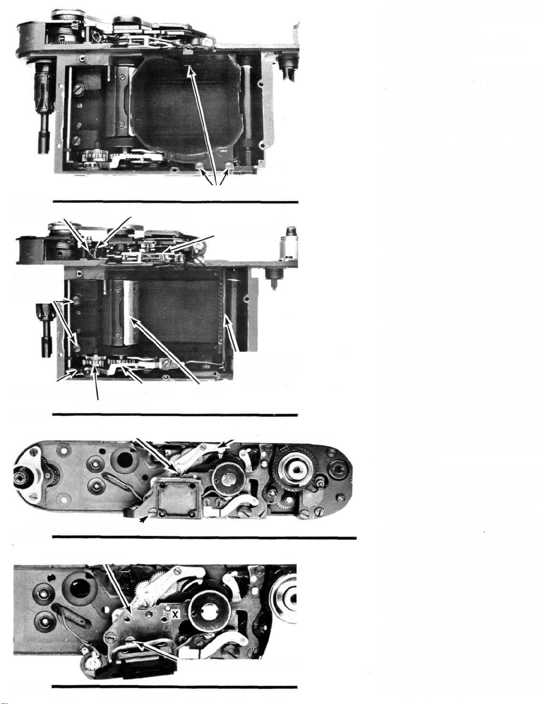
Thenextstepistoseparatethe
bodyshellfromtheshutter
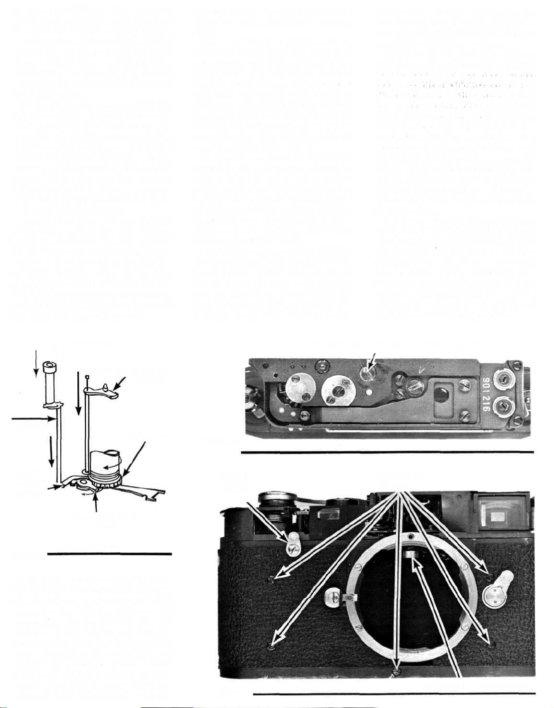
mechanism.First,takeouttherewind
leverbyremovingitsretainingscrew,
Fig.9.Then,removethefivescrews
holdingthebodyshell,alsopointed
outinFig.9.Youmayfindit
necessarytoremovetheframeline
selectorlevertoreachtheupperbody-
shellscrewattherightofthelens
mountingring.
TheAA2weusedfortheillustrations
doesnothavea selftimer.Butif
you'veworkedonM-seriesLeicas
before,youprobablyknowthatthe
cockingleverinmodelswitha self
timerhasa left-handthread.What
youmaynothaveknownisthatyou
don'thavetoremovetheself-timer
cockinglevertopullthebodyshell—
justcocktheselftimerpriorto
separatingthebodyshellfromthe
shuttermechanism.
Somemanipulation— butno
pressure— isnowrequiredtoremove
thebodyshell.Asyoupulloffthebody
shell,pushintherangefindercontrol
arm(againstitstension)for
clearance.
RangefinderAdjustmentPoints
andDisassemblyProcedure
Wecannowmoreeasilypointout
therangefinderadjustments.Besides
thenormalhorizontal(infinity)and
verticaladjustments,thereare
adjustmentsforthelinearityat
differentdistancesandforthe
overtraveloftherangefindercontrol
arm.
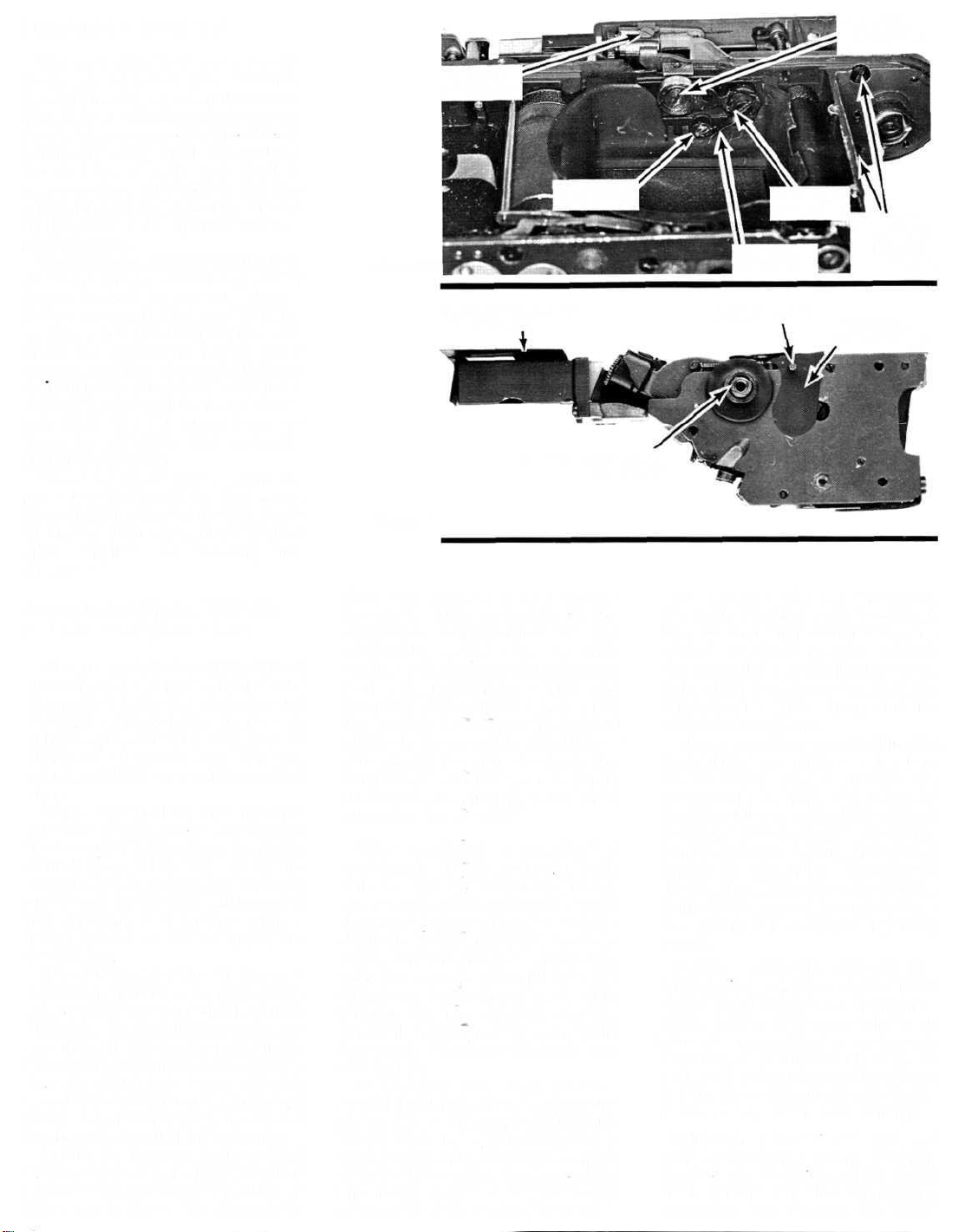
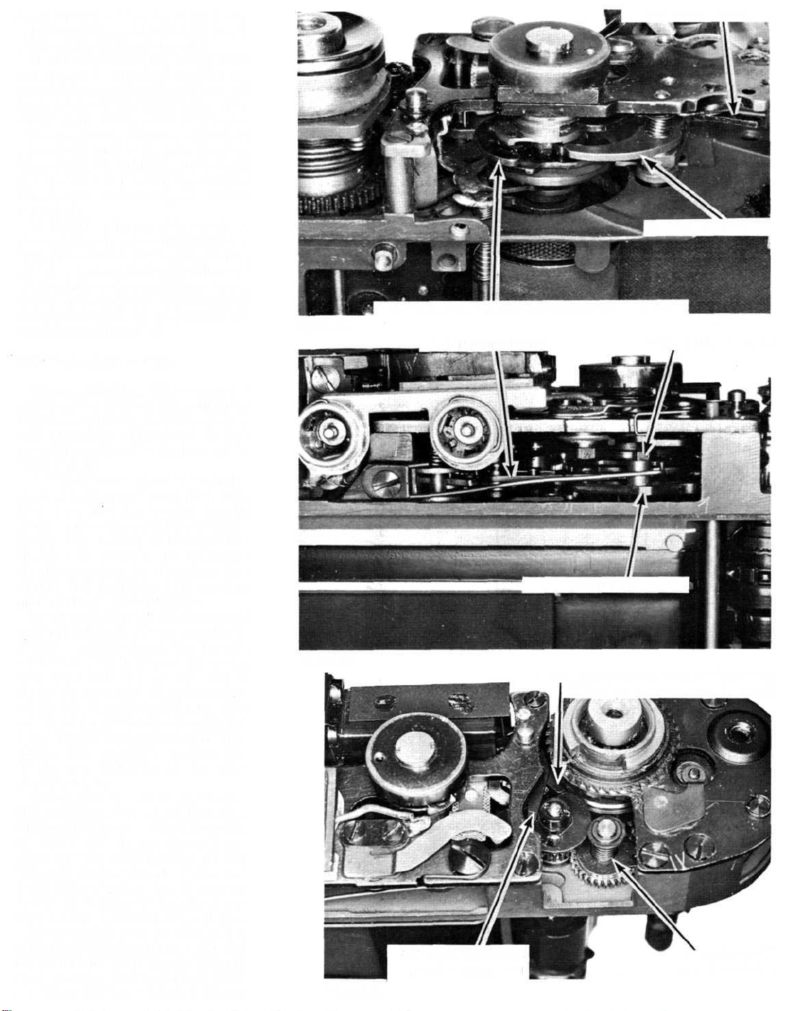
Makeyourinfinityand10-meter
rangefinderadjustmentsbyturning
theeccentricshaftontherangefinder
controlarmroller,Fig.10.Ifthe
rangefinderalignsproperlyatinfinity
and10meters,checkthealignmentof
thesuperimposedimageswitha
targetplacedonemeterfromthe
focalplane.
Theadjustmentpointfortheone-
metertargetistheeccentricatthe
otherendoftherangefindercontrol
arm,Fig.10.Toturntheone-meter
eccentric,firstloosentherangefinder
controlarmretainingscrew.Youmay
havetoalternatebetweenthetwo
eccentrics,checkingandadjustingat
thedesignateddistances,tocorrect
thelinearityforalldistancesettings.
InFig.10,therangefindercontrol
armhasmoved(viaspringtension)
asfarasitcangotowardthefrontof
thecamera.Here,therangefinder
INFINITYAND
10-METER
ADJUSTMENT
Figure10
ONE-METER
ADJUSTMENTRANGEFINDER
ASSEMBLY
RETAINING
SCREWS
THISLIGHTSHIELDMAY
BELOOSEFRAMELINEPINTHISLIGHT
SHIELDISLOOSE
RANGEFINDERCONTROL
ARMSHAFT
Figure 17
stoparmcomesagainstanother
eccentric.Thiseccentricisthe
overtraveladjustmentforthe
rangefindercontrolarm.Inother
words,attheinfinitysettingthelens
pushestherangefindercontrolarm
towardthebackofthecamera.But
therangefindercontrolarmshould
nottouchtheeccentricatinfinity—
youshouldbeabletopushthe
rangefindercontrolarma slight
distancebeyondinfinitybeforeitis
stoppedbytheeccentric.
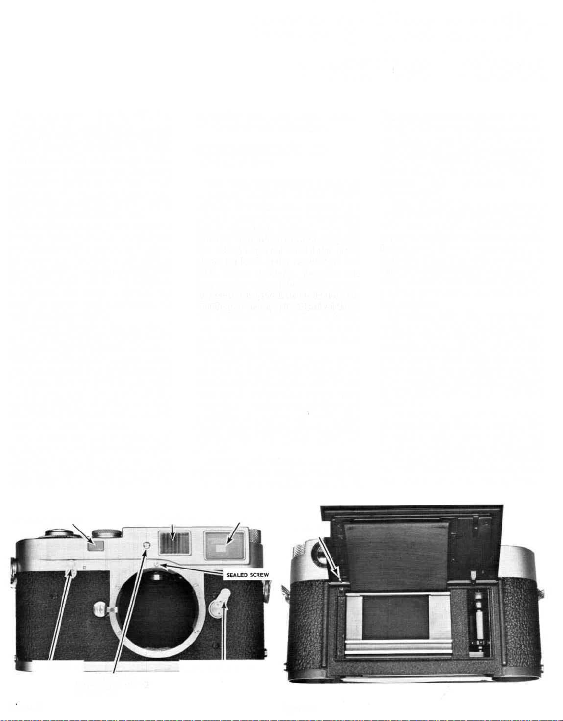
Theverticalrangefinder
adjustment,alsoshowninFig.10,is
stillaccessibleafterreplacingthetop
coverplate;justremovingthescrew
showninFig.1 providesaccesstothe
verticaladjustment point.Soyoucan
makeallrangefinderadjustments
withthecameraassembled— the
distanceadjustmentsareaccessible
throughthelensopening,andthe
verticaladjustmentisaccessible
throughtheclearanceholeinthetop
coverplate.
Removingtherangefinder
assemblydisturbsthesettingofthe
one-metereccentricandcoulddisturb
theovertraveleccentric.Butyoucan
scribethepositionsoftheeccentrics
priortodisassembly.Onreassembly,
aligningthescribemarkssavesa lot
oftimeintheadjustingdepartment.
Now,removethetworangefinder
assemblyretainingscrewsshownin
Fig.10.And,afterscribingtheone-
metereccentric'sposition,remove
therangefindercontrolarmscrew.
Takeouttheone-metereccentric,the
rangefindercontrolarm,andthe
rangefinderstoparm.
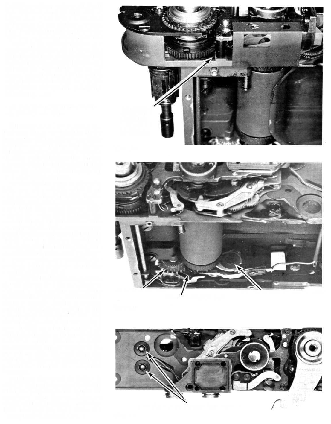
There'sonemorescrewholdingthe
rangefinderassembly— thelong
screwwhichpassesthroughthe
overtraveleccentric.Butyoumay
findthatthisscrewisa littledifficult
toreach.Sowe'vefinallycometothe
purposebehindremovingthebayonet
capinthefocal-planelightshield.
Inserta longscrewdriverthroughthe
lightshieldaccessholeandunscrew
theovertraveleccentricretaining
screw.
Next,carefullyliftoffthe
rangefinderassembly;asyoucansee
inFig.11,there'sa looselightshield
atthebottomoftherangefinder.If
youdoencountera damaged
rangefinder,you'llusuallyhaveto
replacethecompleteassemblyshown
inFig.11— individualrangefinder
replacementpartsarenotavailable.
Althoughyoumayhavereversed
thesequenceinthepast,it'seasierto
removethefocal-planelightshield
aftertakingouttherangefinder
assembly.Soremovethethree
VERTICAL
ADJUSTMENT
OVERTRAVEL
ADJUSTMENT
RANGEFINDER
STOPARM
FOCAL-PLANELIGHTSHIELDRETAININGSCREWS
Figure 12
"FP"SYNCCONTACTS
WHENSELF
TIMERISUSED,
ITISHELD
BYTHESE
TWOSCREWS
SAFETYSWITCHFOR
"X"SYNCCONTACTS
CURTAINWINDGEAR
"X"SYNC
CONTACTS
CURTAIN
DRUM
TUBEFORROUTING
WIRESTO"X"SYNC
CONTACTSAND
SAFETYSWITCH
Figure13
1/8SECONDADJUSTMENTSPEEDSESCAPEMENTADJUSTMENTLEVER
ACCESSORYSHOEMOUNTINGPLATESCREW
Figure14
SPEEDSESCAPEMENTPIVOTSCREW
Figure15
screwsshowninFig.12andliftoutthe
focal-planelightshield.
RemovingAndReplacingThe
SpeedsEscapement
Thepresentstageofdisassembly
maybeasfarasyou'llnormallygo
forroutinecleaningandlubrication.
Butthereisonemorerecommended
step— theremovalofthespeeds
escapementatthetopofthecamera.
Fig.13.
Ifthisisyourfirstencounterwithan
M-seriesLeica,thespeeds
escapementseemsquiteunique.
Varyingamountsofretard
engagementareobtainedbyswinging
theentireescapementarounda pivot
point.Thespeedsescapement
adjustmentlever,Fig.14,rides
againsttheslow-speedcam,oneofthe
camsmovedbythespeedselector.
TheeccentricpointedoutinFig.14
isyouradjustmentpointfortheslow
speeds.Aftermakingthehigh-speed
adjustments(whichwe'lldiscussa
littlelater),turntheadjustmentarm
eccentrictocorrecttheexposureat
the1/8secondsetting.
Toremovethespeedsescapement,
firsttakeoutthescrewholdingthe
accessoryshoemountingplate,Fig.
14.Now,liftasidetheaccessoryshoe
mountingplatetoexposethespeeds
escapementpivotscrew,Fig.15.
Lookingunderthespeedcontrol
bridge,Fig.15,locatethespeeds
escapementpivotspring.Thelong
(upper)endofthespringhookstoa
postontheundersideofthespeed
controlbridge,andtheshortend
hookstoa studonthespeeds
escapement.
Disconnectthelongendofthepivot
springfromthehookingpost.Then,
removethepivotscrew,Fig.15,and
slideoutthespeedsescapement
toward thefrontofthecamera.
Asyou'venodoubtnoticed,the
pivotscrewissealed— inthiscase,
thelockingagentisusedtoholdthe
pivotscrewadjustmentfortheproper
freedomofthespeedsescapement.So
let'stake a momenttodiscussthe
reassemblyofthespeedsescapement
andthepivotscrewadjustment
procedure.
First,setthespeedselectorto1
secondandpushthepalletcam
followertowardthefrontofthe
camera,Fig.16.Placethepivot
springontopofthespeeds
escapementandslidetheescapement
intoplace—makesurethatthepallet
controllever(ontopofthespeeds
SPEEDCONTROLBRIDGE
"FP"CONTACTSGROUNDWIRE
SPEEDSESCAPEMENT
escapement)ishookedbehindthe
palletcamfollower.Replacethepivot
screwandhookthepivotspring.
Now,toadjustthepivotscrew,hold
thespeedsescapementagainstits
springtension—awayfromthespeed
controlcamstack.Tightenthepivot
screwuntilthespeedsescapement
cannotmovetoward thespeedcontrol
camstackunderitsowntension.
Then,backoffthepivotscrewuntil
thespeedsescapementdoesswing
intocontactwiththespeedcontrol
camstack.
Testyouradjustmentbypushing
downonthespeedcontrolbridgeat
thepointmarked"X"inFig.15.The
speedsescapementshouldstillmove
freelywhileyou'reexertingpressure.
Ifitdoesn't,slightlybackoffthepivot
screw.Finally,resealthepivotscrew
toholdyouradjustment.
Slit-WidthAdjustments
Sincewementionedtheslow-speed
adjustment,let'slookattheslit-width
adjustmentatthebackofthecamera.
Theslit-widthadjustmentisthe
eccentricpostontheclosingcurtain
latch,Fig.17.
Saythatyou'vejustreleasedthe
shutteratoneoftheslit-widthspeeds.
Youknowthattheopeningcurtain
startsacrosstheaperture,butthe
closingcurtainisheldbackbythe
closingcurtainlatch.It'suptothe
openingcurtaintodisengagethe
closingcurtainlatchattheproper
timeforthedesiredslitwidth.
Thepartthatdisengagestheclosing
curtainlatchisthedisengaginglever,
Fig.17.Andthedisengagingleveris
controlledbythereleasecam,a cam
thatspinswiththeopeningcurtain
drum.So,oncetheopeningcurtain
hastraveleda sufficientdistance,the
releasecamstrikesthedisengaging
lever.Thedisengaginglever,inturn,
strikestheeccentricpostonthe
closingcurtainlatchandfreesthe
closingcurtain.
Turningthespeedselectortothe
differentshutterspeedspositionsthe
disengaginglever— that'showthe
speedselectorchangestherelease
pointoftheclosingcurtainfor
differentshutterspeeds.Fromthe
frontofthecamera,Fig.16,youcan
seetheendofthedisengaginglever
thatridesagainstthehigh-speedcam.
Theeccentricpostontheclosing
curtainlatchistheadjustmentpoint
foralltheslit-widthspeeds.Turning
theeccentricposttocorrect1/500
secondand1/250secondshouldbring
PALLETCAMFOLLOWER
1/1000SECONDCONTROLSECTIONOFHIGH-SPEEDCAM
Figure16
DISENGAGINGLEVERSLIT-WIDTHECCENTRIC
Figure17
LATCHWHICHLIMITSTHEFORWARDTRAVELOF
THEWINDGEARSONTHECOCKINGCYCLE
LATCHWHICHPREVENTS
SPROCKETBACKLASH
ONE-WAYCLUTCH
FORWINDSTROKE
Figure18
DISENGAGINGLEVER
CLOSINGCURTAINLATCH
intheremainingspeedsaswell.Butif
the1/1000secondisstilloutof
tolerance,youhavea slotted
adjustmentonthehigh-speedcam,
Fig.16;reformingthissectionofthe
high-speedcamaffectsonlythe1/1000-
secondsetting.Infact,inthenewer
versionsoftheM-seriesLeicas,the
high-speedcamisslottedatmostof
theindividualspeedstoallowprecise
adjustmentsthroughoutthespeed
range.Theslow-speedcam,which
controlsthespeedsescapement,also
hasslottedadjustmentpointsfor
individualspeeds.
OtherTestsAndAdjustmentsIn
TheM-SeriesLeicas
Althoughwe'vedisassembledthe
Leicaasfaraswouldnormallybe
necessary,we'llmentionsomeofthe
pointstocheckintheeventyougo
further.Forone,checktheactionof
thethreewindlatches:thelatches
showninFigs.18and19mustalldrop
intoengagementsimultaneouslyat
theendofthewindstroke.
Anothertimingpointisshownin
Fig.20.Thecurtainwindgear
engagesthedrumgeartoadvancethe
curtains.Ifyou'llcocktheshutter—
andholdthewindleverfully
advanced— thefirsttoothinthe
curtainwindgear(clockwiseofthe
slotinthegear,asseenfromthetop)
shouldcenterontheopeningcurtain
latch.Youcanremovethecurtain
windgearbytakingoutthepivotplate
fromthebottomofthecamera,Fig.6.
Soonreassembly,youmusttimethe
curtainwindgeartomeetthe
conditionjustdescribed.
Theplentifuladjustmentpointsare
truetestimonytoLeicaquality.For
example,howmanyfocal-plane
shuttersallowyoutoadjustindividual
shutterspeedswithina range?
Anotherconvincingexampleisthe
alignmentadjustmentforthe
curtains.Inmostfocal-planeshutters,
youstraightena leaningcurtainby
shimmingthetapes.Butmostofthe
M-seriesLeicasprovideeccentric
bushingsfortheupperendsofthetake-
uprollers,Fig.21.Correctingthe
squarenessofthecurtainbarsisjusta
matterofturningtheeccentric
bushings.
Perhapsthewordoftodayis
"SLR,"butmanya connoisseurstill
demandsthecomparativequietand
convenienceoftheM-seriesLeica.So
wehopethisarticlehasbeenofsome
helpingivingtheregalLeicathe
qualityfieldserviceitdeserves.
LATCHWHICH
LATCHESTHE
MAINWIND
GEARATTHE
ENDOF
ITSMOTION
Figure19
CURTAINWINDGEAR
Figure20
CLOSINGCURTAINBRAKEASSEMBLY
OPENINGCURTAINLATCH
ECCENTRICBUSHINGSFORTAKE-UPROLLERS
Figure21

Popular Film Camera manuals by other brands

KMZ Zenit-EM manual

KMZ

KMZ Zenit-EM manual

Nikon FA instruction manual

Nikon

Nikon FA instruction manual

Pentax IQZoom 130M operating manual

Pentax

Pentax IQZoom 130M operating manual

Canon EOS IX 7 instructions

Canon

Canon EOS IX 7 instructions

ZEISS IKON CONTINA IIA Instructions for use

ZEISS IKON

ZEISS IKON CONTINA IIA Instructions for use

Polaroid 170BV Specifications

Polaroid

Polaroid 170BV Specifications

Mamiya M645 Super instructions

Mamiya

Mamiya M645 Super instructions

Samsung FINO 80 SUPER user guide

Samsung

Samsung FINO 80 SUPER user guide

Pentax ME Super operating manual

Pentax

Pentax ME Super operating manual

Canon AE-1 instructions

Canon

Canon AE-1 instructions

Nikon N60 instruction manual

Nikon

Nikon N60 instruction manual

PANAVISION HD900F Operation manual

PANAVISION

PANAVISION HD900F Operation manual

Canon CT1-7462-000 user guide

Canon

Canon CT1-7462-000 user guide

Zenza Bronica S2 instructions

Zenza Bronica

Zenza Bronica S2 instructions

Canon FTb manual

Canon

Canon FTb manual

Minolta MAXXUM 5000I manual

Minolta

Minolta MAXXUM 5000I manual

Olympus 102375 - Stylus Epic Zoom 80 DLX 35mm Camera Instrucciones

Olympus

Olympus 102375 - Stylus Epic Zoom 80 DLX 35mm Camera Instrucciones

Pentax IQZoom 130M operating manual

Pentax

Pentax IQZoom 130M operating manual

manuals.online logo
manuals.online logoBrands
  • About & Mission
  • Contact us
  • Privacy Policy
  • Terms and Conditions

Copyright 2025 Manuals.Online. All Rights Reserved.