manuals.online logo
Brands
  1. Home
  2. •
  3. Brands
  4. •
  5. Lennox
  6. •
  7. Furnace
  8. •
  9. Lennox G23 Series User manual

Lennox G23 Series User manual

Other manuals for G23 Series

2

This manual suits for next models

21

Other Lennox Furnace manuals

Lennox SL280DFNV Series Guide

Lennox

Lennox SL280DFNV Series Guide

Lennox G41UF Series Guide

Lennox

Lennox G41UF Series Guide

Lennox G40UHX Series Installation and operation manual

Lennox

Lennox G40UHX Series Installation and operation manual

Lennox EL280UHE Service manual

Lennox

Lennox EL280UHE Service manual

Lennox ML193UH045P36B Installation and operation manual

Lennox

Lennox ML193UH045P36B Installation and operation manual

Lennox SLP98UH SERIES Guide

Lennox

Lennox SLP98UH SERIES Guide

Lennox Allied Air A93UH1E User manual

Lennox

Lennox Allied Air A93UH1E User manual

Lennox 80UHG2-45 Service manual

Lennox

Lennox 80UHG2-45 Service manual

Lennox SL280UHV Operator's manual

Lennox

Lennox SL280UHV Operator's manual

Lennox G23Q2-50 Installation and operation manual

Lennox

Lennox G23Q2-50 Installation and operation manual

Lennox G40UHX Series Guide

Lennox

Lennox G40UHX Series Guide

Lennox SLO183UFV Series User manual

Lennox

Lennox SLO183UFV Series User manual

Lennox GSR14 User manual

Lennox

Lennox GSR14 User manual

Lennox GHR32 Series Guide

Lennox

Lennox GHR32 Series Guide

Lennox G60DF(X) Series Guide

Lennox

Lennox G60DF(X) Series Guide

Lennox EL180DFE Series User manual

Lennox

Lennox EL180DFE Series User manual

Lennox Allied Air EFV Series User manual

Lennox

Lennox Allied Air EFV Series User manual

Lennox ML193DF User manual

Lennox

Lennox ML193DF User manual

Lennox G43UF SERIES User manual

Lennox

Lennox G43UF SERIES User manual

Lennox ML193UH User manual

Lennox

Lennox ML193UH User manual

Lennox MPGA 075 B3 User guide

Lennox

Lennox MPGA 075 B3 User guide

Lennox ML180UHE Manual

Lennox

Lennox ML180UHE Manual

Lennox Elite series User manual

Lennox

Lennox Elite series User manual

Lennox GSR21Q Series Guide

Lennox

Lennox GSR21Q Series Guide

Popular Furnace manuals by other brands

Unitary products group AHV8 UH installation manual

Unitary products group

Unitary products group AHV8 UH installation manual

VERDER CARBOLITE GERO RHF 14/8 Installation, operation and maintenance instructions

VERDER

VERDER CARBOLITE GERO RHF 14/8 Installation, operation and maintenance instructions

Tempstar B Series Service and technical support manual

Tempstar

Tempstar B Series Service and technical support manual

Carrier Performance 59SP5A Installation, start-up, operating and service and maintenance instructions

Carrier

Carrier Performance 59SP5A Installation, start-up, operating and service and maintenance instructions

Armstrong EG7H SERIES Installation and maintenance instructions

Armstrong

Armstrong EG7H SERIES Installation and maintenance instructions

Payne PG92ESA Installation, start-up, operating and service and maintenance instructions

Payne

Payne PG92ESA Installation, start-up, operating and service and maintenance instructions

NANOE Zetasinter Operation manual

NANOE

NANOE Zetasinter Operation manual

SUPREME FEM10-M2301CM-A Installation instructions and homeowner's manual

SUPREME

SUPREME FEM10-M2301CM-A Installation instructions and homeowner's manual

Johnson Controls TM9T User's information manual

Johnson Controls

Johnson Controls TM9T User's information manual

Fluke 9118A user manual

Fluke

Fluke 9118A user manual

Intertherm M7RL Series user manual

Intertherm

Intertherm M7RL Series user manual

HDG Pelletmaster 15 Operation manual

HDG

HDG Pelletmaster 15 Operation manual

Nortek MG2S Series installation instructions

Nortek

Nortek MG2S Series installation instructions

VERDER CARBOLITE GERO ABF 8/28 Installation, operation and maintenance instructions

VERDER

VERDER CARBOLITE GERO ABF 8/28 Installation, operation and maintenance instructions

Goodman GMV9 Installation & operating instructions

Goodman

Goodman GMV9 Installation & operating instructions

SUPREME SUP10-M2301C Installation instructions and homeowner's manual

SUPREME

SUPREME SUP10-M2301C Installation instructions and homeowner's manual

Dettson AMT400B34-SM1PMA Installation instructions and homeowner's manual

Dettson

Dettson AMT400B34-SM1PMA Installation instructions and homeowner's manual

Evcon DGD 60 MBH installation instructions

Evcon

Evcon DGD 60 MBH installation instructions

manuals.online logo
manuals.online logoBrands
  • About & Mission
  • Contact us
  • Privacy Policy
  • Terms and Conditions

Copyright 2025 Manuals.Online. All Rights Reserved.

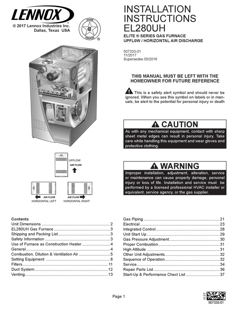
INSTALLATION INSTRUCTIONS
2000 Lennox Industries Inc.
Dallas, Texas, USA
INSTALLATION
INSTRUCTIONS
G23(X) SERIES UNITS
GAS UNITS
503,884M
1/2000
Supersedes 5/99
Table of Contents
Unit Dimensions 2. . . . . . . . . . . . . . . . . . . . . . . . . . . . .
Parts Arrangement 3. . . . . . . . . . . . . . . . . . . . . . . . . . .
Requirements 4. . . . . . . . . . . . . . . . . . . . . . . . . . . . . . . .
General 5. . . . . . . . . . . . . . . . . . . . . . . . . . . . . . . . . . . . .
Combustion, Dilution, & Ventilation Air 5. . . . . . . . . .
Installation - Setting Equipment 7. . . . . . . . . . . . . . . .
Return Air Opening Guidelines 7. . . . . . . . . . . . . . . . .
Filters & Optional Filter Assembly 8. . . . . . . . . . . . . .
Duct System 9. . . . . . . . . . . . . . . . . . . . . . . . . . . . . . . . .
Venting 9. . . . . . . . . . . . . . . . . . . . . . . . . . . . . . . . . . . . .
Gas Piping 16. . . . . . . . . . . . . . . . . . . . . . . . . . . . . . . . .
Electrical 17. . . . . . . . . . . . . . . . . . . . . . . . . . . . . . . . . . .
Unit Start-Up 21. . . . . . . . . . . . . . . . . . . . . . . . . . . . . . .
Gas Pressure Adjustment 22. . . . . . . . . . . . . . . . . . . .
High Altitude Information 23. . . . . . . . . . . . . . . . . . . . .
Other Unit Adjustments 23. . . . . . . . . . . . . . . . . . . . . .
Service 24. . . . . . . . . . . . . . . . . . . . . . . . . . . . . . . . . . . .
Repair Parts List 26. . . . . . . . . . . . . . . . . . . . . . . . . . . .
SureLight Troubleshooting 27. . . . . . . . . . . . . . . . . . . .
Start-Up & Performance Check List 31. . . . . . . . . . . .
RETAIN THESE INSTRUCTIONS
FOR FUTURE REFERENCE
WHAT TO DO IF YOU SMELL GAS:
Do not store or use gasoline or other
flammable vapors and liquids in the vi
cinity of this or any other appliance.
Installation and service must be per
formed by a qualified installer, ser
vice agency or the gas supplier.
Do not try to light any appliance.
Do not touch any electrical switch; do not use
any phone in your building.
Immediately call your gas supplier from a
neighbor's phone. Follow the gas supplier's
instructions.
If you cannot reach your gas supplier, call the
fire department.
Extinguish any open flames.
If the information in this manual is not
followed exactly, a fire or explosion
may result causing property damage,
personal injury, or death.
WARNING
Litho USA
Page 2
G23(X) Unit Dimensions - inches (mm)
AIR FLOW
SUPPLY
AIR
OPENING
FLUE
OUTLET
4 (102)
11/16
(41)
B
C
F
GAS PIPING INLET
(Both Sides)
ELECTRICAL INLETS
(Both Sides)
RETURN AIR
KNOCKOUT
(Either Side)
281/2
(724)
A
23 (584)
115/16 (49)
G
45/8
(117)
TOP VIEW
FRONT VIEW
SIDE VIEW
11/16
(41)
4 (102)
233/4 (603)
25 (635)
5/8
(16)
J
H
5/8 (16)
EXTERNAL
SIDE RETURN
AIR FILTER KIT
(Either Side)
(Optional)
133/16 (335) Left
1315/16 (354) Right
2-3/8 (60) Left
5 (127) Right
Return Air
Knockout (Bottom)
Bottom Return
Air Knockout
187/8
(479)
23 (584)
D
E
Model No. A B C D E F G H J
G23Q2(X)-50
G23Q3(X) 50
in. 40 161/4 141/8 12 12 21/8 5 14 123/4
G23Q3(X)50
G23Q2/3(X)75 mm 1016 413 359 305 305 54 127 356 324
G23Q3(X) 100
in. 40 211/4 191/8 14 14 35/8 71/2 16 143/4
G23Q3(X)100 mm 1016 540 486 356 356 92 191 406 375
G23Q4/5(X)75
G23Q3/4
(
X
)
-100 in. 46 211/4 191/8 18 18 15/8 71/2 20 183/4
G23Q3/4(X) 100
G23Q4/5(X)-100
G23Q3/4(X)-125 mm 1168 540 486 457 457 41 191 508 476
G23Q5/6
(
X
)
125 in. 46 261/4 241/8 18 18 41/8 10 20 183/4
G23Q5/6(X)125
G23Q5/6(X)-150 mm 1168 667 613 457 457 105 254 508 476
Page 3
G23(X) Parts Arrangement
FIGURE 1
G23(X) UNIT WITH PANELS REMOVED
IGNITOR ASSEMBLY
MANIFOLD AND
GAS VALVE
GAS ORIFICE
DURALOKTM
HEAT EXCHANGER
(Assembly)
FLUE
COLLECTOR BOX
TOP CAP GLASS FIBER
GASKET
ORIFICE PLATE
(FLUE TRANSITION
ASSEMBLY)
FLUE OUTLET
GLASS FIBER
GASKET
UPPER VEST
PANEL
FLAME
BAFFLES
(NOxunits only)
RIGHT MANIFOLD BRACKET
ROLL-OUT BRACKET
MID VEST PANEL
PRIMARY LIMIT
MANIFOLD END
PLUG
ROLL-OUT SWITCH
LEFT MANIFOLD BRACKET
COMBUSTION
AIR BLOWER
PRIMARY LIMIT
ALTERNATE STYLE
BURNER ASSEMBLY
CONTROL BOX
SUPPLY AIR
OPENING
TOP CAP
BLOWER
ASSEMBLY
CAPACITOR
AND BRACKET
COMBUSTION
BLOWER
GASKET
FLUE BOX GLASS FIBER
GASKET
COMBUSTION
AIR PROVING
(PRESSURE) SWITCH
DOOR INTERLOCK SWITCH
SURELIGHT CONTROL BOARD
CONTROL
TRANSFORMER
CONTROL VOLTAGE
CIRCUIT BREAKER
Page 4
Requirements
All G23(X) units are Canadian Standards Association
(CSA) certified.
In the USA, installation of Lennox gas central furnaces
must conform with local building codes. In the absence of
local codes, units must be installed according to the cur
rent National Fuel Gas Code (ANSIZ223.1) in the United
States. The National Fuel Gas Code is available from the
following address:
American National Standards Institute, Inc.
11 West 42nd Street
New York, NY 10036
Air supply for combustion and ventilation must conform to
the methods outlined in the current National Fuel Gas Code.
WARNING
Product contains fiberglass wool.
Disturbing the insulation in this product during
installation, maintenance, or repair will expose you
to fiberglass wool dust. Breathing this may cause
lung cancer. (Fiberglass wool is known to the State
of California to cause cancer.)
Fiberglass wool may also cause respiratory, skin,
and eye irritation.
To reduce exposure to this substance or for further
information, consult material safety data sheets
available from address shown below, or contact
your supervisor.
Lennox Industries Inc.
P.O. Box 799900
Dallas, TX 75379-9900
This furnace is CSA certified for installation clearances to
combustible material as listed on the unit rating plate and
in table 1. Accessibility and service clearances must take
precedence over fire protection clearances.
TABLE 1
Clearances Location Inches (mm)
Service access Front 24 (610)
Side and rear 0 (0)
To combustible Top 1 (25)
To
combustible
materials Flue 6 (152)*
Floor 0 (0)**
Around com
bustion cham
Front
B1Vent
3 (76)
b
us
ti
on c
h
am
ber air opening
Front
Single Wall Vent
4 (102)
NOTE-Service access clearance must be maintained.
* 1 inch (25mm) for type B1" Vent Pipe.
**For installation on combustible floors, appliance shall not be installed
directly on carpeting, tile, or other combustible material other than wood
flooring.
Vent installations must be in accordance with the pro
vided venting tables and applicable provisions of local
building codes.
For installation in a residential garage, the furnace must
be installed so that the burner(s) and the ignition source
are located no less than 18 inches (457 mm) above the
floor. The furnace must be located or protected to avoid
physical damage by vehicles. When a furnace is installed
in a public garage, hangar, or other building that has a
hazardous atmosphere, the furnace must be installed ac
cording to recommended good practice requirements
and current National Fuel Gas Code.
Unit must be adjusted to obtain a temperature rise within
the range specified on appliance rating plate.
G23(X) units must be installed so that electrical compo
nents are protected from water.
When the furnace is used with cooling units, it shall be
installed in parallel with, or on the upstream side of, cool
ing units to avoid condensation in the heating compart
ment. With a parallel flow arrangement, a damper (or
other means to control the flow of air) must adequately
prevent chilled air from entering the furnace. If the damp
er is manually operated, it must be equipped to prevent
operation of either the heating or the cooling unit, unless
it is in the full HEAT" or COOL" setting.
When installed, the furnace must be electrically
grounded according to local codes. In addition, in the
United States, installation must conform with the current
National Electric Code, ANSI/NFPA No. 70. The Nation
al Electric Code (ANSI/NFPA No. 70) is available from
the following address:
National Fire Protection Association
1 Battery March Park
Quincy, MA 02269
Field wiring connection with unit must meet or exceed
specifications of type T wire and withstand a 63F (17C)
temperature rise.
This furnace is designed for a minimum continuous return
air temperature of 60° dry bulb for cases in which a ther
mostat night setback is used. Return air temperature
must not exceed a maximum of 85F db.
NOTE - G23(X) series units must not be used as a
construction heater during any phase of construction.
Very low return air temperatures, harmful vapors and
misplacement of the filters will damage the unit and low
er its efficiency.
Page 5
General
These instructions are intended as a general guide and
do not supersede local codes in any way. Consult authori
ties having jurisdiction before installation.
A-Shipping and Packing List
1 - Assembled G23(X) furnace
1 - Bag assembly containing
1-Electrical makeup box
3-Wire nuts
1-Green ground wire
1-Brown accessory wire
1-Wiring harness
1-Snap bushing
2-Filter clips
B-Shipping Damage
Check equipment for shipping damage. If you find any
damage, immediately contact the last carrier.
Combustion, Dilution, & Ventilation Air
In the past, there was no problem in bringing in sufficient
outdoor air for combustion. Infiltration provided all the air
that was needed. In today's homes, tight construction
practices make it necessary to bring in air from outside for
combustion. Take into account that exhaust fans, ap
pliance vents, chimneys, and fireplaces force additional
air that could be used for combustion out of the house.
Unless outside air is brought into the house for combus
tion, negative pressure (outside pressure is greater than
inside pressure) will build to the point that a downdraft can
occur in the furnace vent pipe or chimney. As a result,
combustion gases enter the living space creating a poten
tially dangerous situation.
In the absence of local codes concerning air for combus
tion and ventilation, use the guidelines and procedures in
this section to install G23(X) furnaces to ensure efficient
and safe operation. You must consider combustion air
needs and requirements for exhaust vents and gas pip
ing. A portion of this information has been reprinted with
permission from the National Fuel Gas Code
(ANSIZ223.1). This reprinted material is not the com
plete and official position of the ANSI on the referenced
subject, which is represented only by the standard in its
entirety.
All gasfired appliances require air for the combustion
process. If sufficient combustion air is not available, the
furnace or other appliance will operate inefficiently and
unsafely. Enough air must be provided to meet the needs
of all fuelburning appliances and appliances such as ex
haust fans which force air out of the house. When fire
places, exhaust fans, or clothes dryers are used at the
same time as the furnace, much more air is required to en
sure proper combustion and to prevent a downdraft. In
sufficient air causes incomplete combustion which can re
sult in carbon monoxide.
Combustion Air Requirements
WARNING
Insufficient combustion air can cause headaches,
nausea, dizziness or asphyxiation. It will also cause
excess water in the heat exchanger resulting in rust
ing and premature heat exchanger failure. Exces
sive exposure to contaminated combustion air will
result in safety and performance related problems.
Avoid exposure to the follow-ing substances in the
combustion air supply:
Permanent wave solutions
Chlorinated waxes and cleaners
Chlorine base swimming pool chemicals
Water softening chemicals
De-icing salts or chemicals
Carbon tetrachloride
Halogen type refrigerants
Cleaning solvents (such as perchloroethylene)
Printing inks, paint removers, varnishes, etc.
Hydrochloric acid
Cements and glues
Antistatic fabric softeners for clothes dryers
Masonry acid washing materials
In addition to providing combustion air, fresh outdoor air
dilutes contaminants in the indoor air. These contami
nants may include bleaches, adhesives, detergents, sol
vents and other contaminants which can corrode furnace
components.
The requirements for providing air for combustion and
ventilation depend largely on whether the furnace is
installed in an unconfined or a confined space.
Unconfined Space
An unconfined space is an area such as a basement or
large equipment room with a volume greater than 50 cu
bic feet (1.42 m3) per 1,000 Btu (.29 kW) per hour of the
combined input rating of all appliances installed in that
space. This space also includes adjacent rooms which
are not separated by a door. Though an area may appear
to be unconfined, it might be necessary to bring in outdoor
air for combustion if the structure does not provide
enough air by infiltration. If the furnace is located in a
building of tight construction with weather stripping and
caulking around the windows and doors, follow the proce
dures in the air from outside section.
Confined Space
A confined space is an area with a volume less than 50
cubic feet (1.42 m3) per 1,000 Btu (.29 kW) per hour of the
combined input rating of all appliances installed in that
space. This definition includes furnace closets or small
equipment rooms.
Page 6
When the furnace is installed so that supply ducts carry air
circulated by the furnace to areas outside the space con
taining the furnace, the return air must be handled by
ducts which are sealed to the furnace casing and which
terminate outside the space containing the furnace. This
is especially important when the furnace is mounted on a
platform in a confined space such as a closet or small
equipment room. Even a small leak around the base of
the unit at the platform or at the return air duct connection
can cause a potentially dangerous negative pressure
condition. Air for combustion and ventilation can be
brought into the confined space either from inside the
building or from outside.
Air from Inside
If the confined space that houses the furnace adjoins a
space categorized as unconfined, air can be brought in by
providing two permanent openings between the two
spaces. Each opening must have a minimum free area of 1
square inch (645 mm2) per 1,000 Btu (.29 kW) per hour of
total input rating of all gas-fired equipment in the confined
space. Each opening must be at least 100 square inches
(64516 mm2). One opening shall be within 12 inches (305
mm) of the top of the enclosure and one opening within 12
inches (305 mm) of the bottom. (See figure 2).
EQUIPMENT IN CONFINED SPACE
ALL AIR FROM INSIDE
CHIMNEY OR
GAS VENT
WATER
HEATER
OPENINGS
(To Adjacent
Room)
FIGURE 2
NOTE-Each opening shall have a free area of at least one square
inch per 1,000 Btu per hour of the total input rating of all equipment in
the enclosure, but not less than 100 square inches.
G23
FURNACE
Air from Outside
If air from outside is brought in for combustion and ventila
tion, the confined space must have two permanent open
ings. One opening shall be within 12 inches (305 mm) of
the top of the enclosure and one opening within 12 inches
(305 mm) of the bottom. These openings must communi
cate directly or by ducts with the outdoors or spaces
(crawl or attic) that freely communicate with the outdoors
or indirectly through vertical ducts. Each opening shall
have a minimum free area of 1 square inch (645 mm2) per
4,000 Btu (1.17 kW) per hour of total input rating of all
equipment in the enclosure. (See figures 3 and 4). When
communicating with the outdoors through horizontal
ducts, each opening shall have a minimum free area of 1
square inch (645 mm2) per 2,000 Btu (.56 kW) per total
input rating of all equipment in the enclosure. See figure 5.
When ducts are used, they shall be of the same cross-
sectional area as the free area of the openings to which
they connect. The minimum dimension of rectangular air
ducts shall be no less than 3 inches (75 mm). In calculat
ing free area, the blocking effect of louvers, grilles, or
screens must be considered. If the design and free area of
protective covering is not known for calculating the size
opening required, it may be assumed that wood louvers
will have 20 to 25 percent free area and metal louvers and
grilles will have 60 to 75 percent free area. Louvers and
grilles must be fixed in the open position or interlocked
with the equipment so that they are opened automatically
during equipment operation.
EQUIPMENT IN CONFINED SPACE
ALL AIR FROM OUTSIDE
(Inlet Air from Crawl Space and
Outlet Air to Ventilated Attic)
NOTE-The inlet and outlet air openings shall each have a free area
of at least one square inch per 4,000 Btu per hour of the total input
rating of all equipment in the enclosure.
VENTILATION LOUVERS
(Each end of attic)
OUTLET
AIR WATER
HEATER
INLET
AIR
CHIMNEY OR
GAS VENT
VENTILATION
LOUVERS
(For unheated crawl
space)
FIGURE 3
G23
FURNACE
EQUIPMENT IN CONFINED SPACE
ALL AIR FROM OUTSIDE
(All Air Through Ventilated Attic)
NOTE-The inlet and outlet air openings shall each have a free area
of at least one square inch per 4,000 Btu per hour of the total input
rating of all equipment in the enclosure.
CHIMNEY
OR GAS
VENT
WATER
HEATER
OUTLET
AIR
VENTILATION LOUVERS
(Each end of attic)
INLET AIR
(Ends 12 in. above
bottom)
FIGURE 4
G23
FURNACE
Page 7
EQUIPMENT IN CONFINED SPACE
ALL AIR FROM OUTSIDE
OUTLET AIR
INLET AIR
WATER
HEATER
CHIMNEY
OR GAS
VENT
FIGURE 5
NOTE-Each air duct opening shall have a free area of at least one
square inch per 2,000 Btu per hour of the total input rating of all
equipment in the enclosure. If the equipment room is located
against an outside wall and the air openings communicate directly
with the outdoors, each opening shall have a free area of at least
one square inch per 4,000 Btu per hour of the total input rating of all
other equipment in the enclosure.
G23
FURNACE
Installation - Setting Equipment
Select a location that allows for required clearances listed
on the unit rating plate. Also consider gas supply connec
tions, electrical supply, vent connection and installation
and service clearances [24 inches (610 mm) at unit front].
The furnace must be level.
NOTE - 1/3 and 1/2 hp blower motors are equipped with
either four flexible mounting legs or three flexible legs and
one rigid leg. The rigid leg is equipped with a shipping bolt
and a flat white plastic washer (rather than the rubber
mounting grommet used with a flexible mounting leg).
This shipping bolt and flat washer must be removed be-
fore the furnace is put into operation. Once the shipping
bolt and washer are removed, the rigid leg will not touch
the blower housing.
Return Air Opening Guidelines
WARNING
Blower door must be securely in place when blower
and burners are operating. Gas fumes, which could
contain carbon monoxide, can be drawn into living
space resulting in personal injury or death.
WARNING
Improper installation of unit can result in personal
injury or death. Combustion and flue products
must never be allowed to enter the return air system
or air in the living space. Use sheet metal screws
and joint tape to seal return air system to furnace.
In platform installations with furnace return, the fur
nace should be sealed airtight to the return air ple
num. A door must never be used as a portion of the
return air duct system. The base must provide a
stable support and an airtight seal to the furnace.
Allow absolutely no sagging, cracks, gaps, etc.
For no reason should return and supply air duct
systems ever be connected to or from other heating
devices such as a fireplace or stove, etc. Fire, ex
plosion, carbon monoxide poisoning, personal in
jury and/or property damage could result.
Return air can be brought in either side or at the bottom of
the unit. Scribe lines show the outline of each side and the
bottom return air opening.
Bottom Return Air Applications
If cold air return is to terminate through the floor under the
furnace, a direct, airtight and sealed connection must be
made to the bottom of the furnace.
1 - Cut opening in floor or platform. Using knockouts
provided, cut bottom of base panel. See figure 6.
FIGURE 6
KNOCKOUT PATTERN FOR BOTTOM RETURN
AIR APPLICATION
2 - Bend a flange on return air plenum and lower into
floor or platform opening. See figure 7.
3 - Position unit over return air opening. Seal unit air
tight with return air plenum.
Page 8
FIGURE 7
G23 UNIT
RETURN AIR
PLENUM
PROPERLY
SIZED FLOOR
OPENING
BOTTOM RETURN AIR APPLICATION
Side Return Air Applications
For installations where the return air is taken from a return
air drop, unit may be installed using either the left or right
side of furnace.
For side return air applications, cut furnace cabinet at
maximum dimensions given on page 2. Embossed cor
ners are provided on both cabinet sides for return air
opening location.
Filters & Optional Filter Assembly
This unit is not equipped with a filter. Filter racks and reus
able foam filters are available from Lennox in single kits
(44J20 for 14 x 25 filters; 44J22 for 16 x 25 filters; 44J21
for 20 x 25 filters) or 10pack kits (66K61 for 14 x 25 filters;
66K63 for 16 x 25 filters; 66K62 for 20 x 25 filters). A filter
must be in place any time the unit is in operation.
Bottom Return Air Applications
1 - Remove blower access panel.
2 - Install filter clips, provided with unit, by slipping
folded section of clip on edge of bottom opening. See
figure 8.
3 - Place filter in bottom of blower compartment beneath
rear filter clip. Press down on filter sides. Filter clips
flex allowing filter to snap into place.
4 - To remove filter, press clip and pull filter up and out.
Side Return Air Applications
An external filter rack, ordered separately, is available
from Lennox.
FIGURE 8
BOTTOM RETURN FILTER INSTALLATION
FURNACE
BASE BOTTOM
REAR FILTER
CLIP
RETURN AIR OPENING
SIDE FILTER
CLIPS (2)
FURNACE
FRONT
FURNACE
BACK
1 - Align filter rack opening with the inside edge of the
side return opening. Bottom of rack should be
approximately 1 inch (25.4mm) from the bottom and
3 inches (76mm) from the front of the unit.
2 - Screw filter rack into place with the six self drill, self
tap screws provided in the kit. See figure 9.
3 - Push filter door pins through the two holes in filter
door from the inside of the uchannel. See figure 10.
4 - Position filter door on end of filter so that the thumb
tab side of the filter door is away from the furnace.
Squeeze thumb tabs to secure filter to door.
FIGURE 9
SIDE RETURN FILTER INSTALLATION
(Inches-mm)
RETURN
AIR OPENING
1-15/16 in.
(49)
BLOWER DECK
15/16 in.
(24)
CABINET BASE BOTTOM
RETURN AIR PLENUM SIZE
12-3/4 in. X 23-1/2 in. (324 X 597)
for 14 in. Filter
14-3/4 in. x 23-1/2 in. (375 x 597)
for 16 in. filter
18-3/4 in. x 23-1/2 in. (476 x 597)
for 20 in. Filter
12 in. (305) for
14 in. Filter
14 in. (356) for
16 in. filter
18 in. (457) for
20 in. Filter
Page 9
5 - Guide filter and filter door into the filter rack which is
installed on the side of the furnace. Push door into fil
ter rack until secure.
6 - To remove filter, pull filter door pins until door is re
leased from filter rack.
FIGURE 10
FILTER DOOR ASSEMBLY
FILTER DOOR
PINS
FILTER
DOOR FILTER
FILTER DOOR
PIN
TAB
TAB
Duct System
Size and install supply and return air duct system using
industryapproved standards that result in a quiet and
low-static system with a uniform air distribution. Refer
to ACCA (Air Conditioning Contractors of America)
Manual N.
Supply Air Plenum
Furnaces installed without a cooling coil require the
installation of a removable access panel in the supply air
duct. The access panel should be large enough to permit
inspection (either by smoke or reflected light) of the heat
exchanger for leaks after installation. The furnace ac
cess panel must always be in place when the furnace is
operating and it must not allow leaks into the supply air
duct system.
Return Air Plenum
NOTE - For bottom return air, return air duct should be se
cured to the unit using rivets or Slocks. For side return air,
secure return air duct to filter rack using screws. When us
ing screws, take care to avoid interference with the filter
which may cause improper filtration.
Return air must not be drawn from a room where this
furnace, or any other gas appliance (ie., a water heat
er), is installed. When return air is drawn from a room,
a negative pressure is created in the room. If a gas ap
pliance is operating in a room with negative pressure, the
flue products can be pulled back down the vent pipe and
into the room. This reverse flow of the flue gas may result
in incomplete combustion and the formation of carbon
monoxide gas. This toxic gas might then be distributed
throughout the house by the furnace duct system.
Venting
G23(X) series furnaces must be vented in compliance
with all local codes, the venting tables provided in this
manual, and these instructions.
The G23(X) series units are classified as fan assisted
Category I type furnaces when vertically vented accord
ing to the latest edition of ANSI Z21.47 Central Furnace
Standard in the USA. The definition of a fan assisted
Category I type furnace is an appliance equipped with an
integral mechanical means to either draw or force prod
ucts of combustion through the combustion chamber and/
or heat exchanger.
The vent sizing tables in this manual were extracted from
the National Fuel Gas Code (NFPA 54 / ANSI Z223.1) and
are provided as a guide for proper vent installation. Prop
er application, termination, construction and location of
vents must conform to local codes having jurisdiction. In
the absence of local codes, the NFGC serves as the de
fining document.
Refer to the tables and the venting information contained
in these instructions to properly size and install the vent
ing system.
The G23(X) series units have the following flue collar
sizes: -50 unit, 3 inch diameter; -75 and -100 units, 4 inch
diameter; and -125 & -150 units, 5 inch diameter. Use this
information in conjunction with the provided venting
tables to properly size the vent or vent connector that at
taches to the furnace flue collar.
Venting Using a Masonry Chimney
The following additional requirements apply when a lined
masonry chimney is used to vent an G23X furnace.
A Category I appliance must never be connected to a
chimney that is servicing a solid-fuel appliance. If a fire
place chimney flue is used to vent this appliance, the fire
place opening must be permanently sealed.
A chimney with one or more sides exposed to the outside
of the structure is considered to be an exterior chimney. A
Type B or listed chimney lining system passing through an
unused masonry chimney flue is not considered to be ex
posed to the outdoors.
Masonry chimneys used to vent Category I central fur
naces must be either tilelined or lined with a listed metal
lining system or dedicated gas vent. Unlined masonry
chimneys are prohibited.
Page 10
FIGURE 11
COMMON VENTING USING TILE-LINED INTERIOR MASONRY
CHIMNEY AND COMBINED VENT CONNECTOR
G23
OTHER APPLIANCE
VENT
CONNECTOR
(Double-walled,
single-walled, or in
sulated single-
walled pipe)
MINI. LENGTH = AS SHORT
AS PRACTICAL.
FOR MAX. LENGTH SEE ITEM 4, ON
THE FOLLOWING PAGE.
INTERIOR TILE-
LINED MASONRY
CHIMNEY
NOTE - CHIMNEY MUST BE
PROPERLY SIZED PER THE
PROVIDED VENTING TABLES
OR LINED WITH LISTED METAL
LINING SYSTEM.
NOTE - If vent connector length exceeds 15
ft. (4.5 m), entire length of single-walled
vent connector must be insulated.
PERMANENTLY SEALED
FIREPLACE OPENING
A fan-assisted furnace may be commonly vented into an
existing lined masonry chimney if the following conditions
are met:
1 - The chimney is currently serving at least one draft
hood equipped appliance.
2 - The vent connectors and chimney are sized in accor
dance with the provided venting tables.
IMPORTANT
SINGLE appliance venting of a fanassisted fur
nace into a tilelined masonry chimney (interior or
outside wall) is PROHIBITED. The chimney must
first be lined with either type B1 vent or an insu
lated single wall flexible vent lining system, sized
according to the provided venting tables.
See figures 11 and 12 for common venting.
A type B1 vent or masonry chimney liner shall terminate
above the roof surface with a listed cap or a listed roof as
sembly according to the terms of their respective listings
and the vent manufacturer's instructions.
Do not install a manual damper, barometric draft regula
tor, or flue restrictor between the furnace and the chim
ney.
If type B doublewall vent is used inside a chimney, no oth
er appliance can be vented into the chimney. Outer wall of
type B vent pipe must not be exposed to flue products.
Insulation for the flexible vent pipe must be an encapsu
lated fiberglass sleeve recommended by the flexible vent
pipe manufacturer. See figure 12.
The space between the liner and the chimney wall
should NOT be insulated with puffed mica or any oth
er loose granular insulating material.
FIGURE 12
COMMON VENTING USING
METAL-LINED MASONRY CHIMNEY
4 IN. MIN.
(102mm)
5 FT. (1.5 m)
MINIMUM MIN. LENGTH -- AS
SHORT AS PRACTICAL
MAX. LENGTH -- SEE
ITEM 10, PAGE 11
SEALED
PERMANENTLY
SEALED FIREPLACE
OPENING
EXTERIOR
CHIMNEY WITH B
VENT OR
INSULATED
FLEXIBLE VENT
PIPE.