manuals.online logo
Brands
  1. Home
  2. •
  3. Brands
  4. •
  5. Lennox
  6. •
  7. Furnace
  8. •
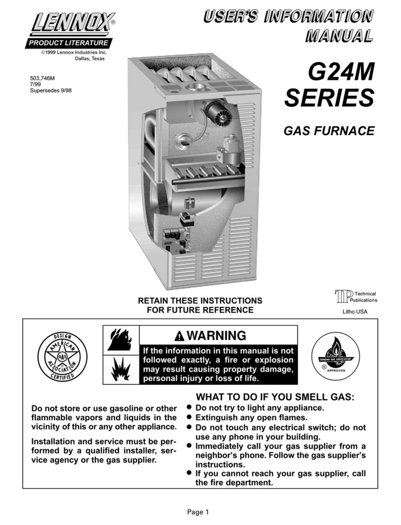
  9. Lennox G24MCE2-45 User manual

Lennox G24MCE2-45 User manual

This manual suits for next models

9

Other Lennox Furnace manuals

Lennox EL195DF SERIES User manual

Lennox

Lennox EL195DF SERIES User manual

Lennox SL297UHNV Series Guide

Lennox

Lennox SL297UHNV Series Guide

Lennox DAVE LENNOX SIGNATURE SL297UHNV User manual

Lennox

Lennox DAVE LENNOX SIGNATURE SL297UHNV User manual

Lennox Elite G61MPV36B-045 User manual

Lennox

Lennox Elite G61MPV36B-045 User manual

Lennox ML193UH030XE36B User manual

Lennox

Lennox ML193UH030XE36B User manual

Lennox 16L23 User manual

Lennox

Lennox 16L23 User manual

Lennox G50DF Series Guide

Lennox

Lennox G50DF Series Guide

Lennox EL296UHV series Guide

Lennox

Lennox EL296UHV series Guide

Lennox A97UH2E User manual

Lennox

Lennox A97UH2E User manual

Lennox G43UF SERIES Installation and operation manual

Lennox

Lennox G43UF SERIES Installation and operation manual

Lennox EL195UHNE Series User manual

Lennox

Lennox EL195UHNE Series User manual

Lennox G60UHV User manual

Lennox

Lennox G60UHV User manual

Lennox 20 User manual

Lennox

Lennox 20 User manual

Lennox ML180DF045P24A User manual

Lennox

Lennox ML180DF045P24A User manual

Lennox EL296DFE Series User manual

Lennox

Lennox EL296DFE Series User manual

Lennox G71P User manual

Lennox

Lennox G71P User manual

Lennox Elite ELO183DH Series User manual

Lennox

Lennox Elite ELO183DH Series User manual

Lennox G50UHi Series Installation and operation manual

Lennox

Lennox G50UHi Series Installation and operation manual

Lennox ML195UH User manual

Lennox

Lennox ML195UH User manual

Lennox Elite series User manual

Lennox

Lennox Elite series User manual

Lennox Allied Air A96UH2E User manual

Lennox

Lennox Allied Air A96UH2E User manual

Lennox 80G1DF User manual

Lennox

Lennox 80G1DF User manual

Lennox Merit Series User manual

Lennox

Lennox Merit Series User manual

Lennox SIGNATURE SLP99DFV User manual

Lennox

Lennox SIGNATURE SLP99DFV User manual

Popular Furnace manuals by other brands

Unitary products group AHV8 UH installation manual

Unitary products group

Unitary products group AHV8 UH installation manual

VERDER CARBOLITE GERO RHF 14/8 Installation, operation and maintenance instructions

VERDER

VERDER CARBOLITE GERO RHF 14/8 Installation, operation and maintenance instructions

Tempstar B Series Service and technical support manual

Tempstar

Tempstar B Series Service and technical support manual

Carrier Performance 59SP5A Installation, start-up, operating and service and maintenance instructions

Carrier

Carrier Performance 59SP5A Installation, start-up, operating and service and maintenance instructions

Armstrong EG7H SERIES Installation and maintenance instructions

Armstrong

Armstrong EG7H SERIES Installation and maintenance instructions

Payne PG92ESA Installation, start-up, operating and service and maintenance instructions

Payne

Payne PG92ESA Installation, start-up, operating and service and maintenance instructions

NANOE Zetasinter Operation manual

NANOE

NANOE Zetasinter Operation manual

SUPREME FEM10-M2301CM-A Installation instructions and homeowner's manual

SUPREME

SUPREME FEM10-M2301CM-A Installation instructions and homeowner's manual

Johnson Controls TM9T User's information manual

Johnson Controls

Johnson Controls TM9T User's information manual

Fluke 9118A user manual

Fluke

Fluke 9118A user manual

Intertherm M7RL Series user manual

Intertherm

Intertherm M7RL Series user manual

HDG Pelletmaster 15 Operation manual

HDG

HDG Pelletmaster 15 Operation manual

Nortek MG2S Series installation instructions

Nortek

Nortek MG2S Series installation instructions

VERDER CARBOLITE GERO ABF 8/28 Installation, operation and maintenance instructions

VERDER

VERDER CARBOLITE GERO ABF 8/28 Installation, operation and maintenance instructions

Goodman GMV9 Installation & operating instructions

Goodman

Goodman GMV9 Installation & operating instructions

SUPREME SUP10-M2301C Installation instructions and homeowner's manual

SUPREME

SUPREME SUP10-M2301C Installation instructions and homeowner's manual

Dettson AMT400B34-SM1PMA Installation instructions and homeowner's manual

Dettson

Dettson AMT400B34-SM1PMA Installation instructions and homeowner's manual

Evcon DGD 60 MBH installation instructions

Evcon

Evcon DGD 60 MBH installation instructions

manuals.online logo
manuals.online logoBrands
  • About & Mission
  • Contact us
  • Privacy Policy
  • Terms and Conditions

Copyright 2025 Manuals.Online. All Rights Reserved.

Page 1
PRODUCT LITERATURE

2000 Lennox Industries Inc.
Dallas, Texas
RETAIN THESE INSTRUCTIONS
FOR FUTURE REFERENCE
INSTALLATION
INSTRUCTIONS
G24MCE Series
GAS-FIRED FURNACE
Direct Spark Ignition
503,95 M
05/2000
Supersedes 11/99
Ta le of Contents
G24MCE Unit Dimensions 2. . . . . . . . . . . . . . . . . . . .
G24MCE GasĆFired Furnace 3. . . . . . . . . . . . . . . . . .
Shipping and Packing List 3. . . . . . . . . . . . . . . . . . . . .
Requirements 3. . . . . . . . . . . . . . . . . . . . . . . . . . . . . . .
General 3. . . . . . . . . . . . . . . . . . . . . . . . . . . . . . . . . . . .
Combustion, Dilution & Ventilation Air 4. . . . . . . . . .
Setting Equipment . . . . . . . . . . . . . . . . . . . . . . . . . . .
Duct System 9. . . . . . . . . . . . . . . . . . . . . . . . . . . . . . . .
Venting 9. . . . . . . . . . . . . . . . . . . . . . . . . . . . . . . . . . . . .
Vertical Flue Using Metal Flue Pipe 9. . . . . . . . . . .
Vertical Flue Using Lined Masonry Chimney 11. .
Horizontal Flue Using Metal Flue Pipe 12. . . . . . .
Gas Piping 13. . . . . . . . . . . . . . . . . . . . . . . . . . . . . . . . .
Electrical 15. . . . . . . . . . . . . . . . . . . . . . . . . . . . . . . . . .
Unit Start-up 18. . . . . . . . . . . . . . . . . . . . . . . . . . . . . . .
Unit Adjustments 19. . . . . . . . . . . . . . . . . . . . . . . . . . .
Service 20. . . . . . . . . . . . . . . . . . . . . . . . . . . . . . . . . . . .
Technical Data Table 22. . . . . . . . . . . . . . . . . . . . . . . .
Ignition Control Board Diagnostic Codes 23. . . . . . .
Troubleshooting 24. . . . . . . . . . . . . . . . . . . . . . . . . . . .
Repair Parts List 27. . . . . . . . . . . . . . . . . . . . . . . . . . . .
G24MCE Parts Arrangement 27. . . . . . . . . . . . . . . . .
G24MCE Start-up & Performance Check List 28. . .
WHAT TO DO IF YOU SMELL GAS:
If the information in this manual is not
followed exactly, a fire or explosion
may result causing property damage,
personal injury or loss of life.
WARNING
Do not store or use petrol or other
flamma le vapours and liquids in the
vicinity of this or any other appliance.
Installation and service must e perĆ
formed y a qualified installer, serĆ
vice agency or the gas supplier.
Do not try to light any appliance.
Do not touch any electrical switch; do not
use any telephone in your uilding.
Immediately call your gas supplier from a
neigh or's telephone. Follow the gas supĆ
plier's instructions.
If you cannot reach your gas supplier, call
the local fire rigade.
Extinguish any open flames.
Litho USA
Page 2
G24MCE Unit Dimensions - millimeters
G24MCE Series
SUPPLY
AIR
OPENING
A
B
*C
**C
RETURN AIR
KNOCKOUT
(Either Side)
Return Air
Opening
Return Air
Opening
GAS PIPING
INLET
(Both Sides)
ELECTRICAL
INLETS
(Both Sides)
FLUE
OUTLET
D
AIR FLOW
FRONT VIEW SIDE VIEW
TOP VIEW
F Left Side
G Right Side
752
*495
495
495
381
51
E
25
GAS PIPING
INLET
ELECTRICAL INLETS
(Top & Bottom)
19
105
*483
Unit shown in upflow position. Rotate 180° for
downflow applications and 90° clockwise or
counterclockwise for horizontal applications.
25
25
25
25
2525 25
*NOTE - The supply air opening is equipped with a 19 mm scored
flange that may e ent 90_ for plenum connection.
The dimensions shown were taken after the flange was ent.
The dou le scored flange at the front of the supply air
opening may e ent for a total opening dimension
(front to rear) of either 495 mm or 483 mm.
**NOTEĊ The return air opening is
equipped with a 19 mm scored flange
that may e ent 90_ for plenum conĆ
nection. The dimensions shown were
taken after the flange was ent.
Model No. A B C D E F G
G24MCE2Ć45
G24MCE3 0/75
mm
432
921
381
171
2
293
1 5
G24MCE3Ć 0/75
G24MCE4Ć75
mm 432 921 381 171 2 293 1 5
G24MCE4/5Ć100
mm
521
991
470
213
108
331
203
G24MCE4/5
Ć
100
G24MCE4/5Ć120 mm 521 991 470 213 108 331 203
G24MCE4/5 140
mm
591
991
540
248
108
329
180
G24MCE4/5Ć140 mm 591 991 540 248 108 329 180
Page 3
G24MCE GasĆFired Furnace
The G24MCE multi-position gas furnace is shipped ready
for installation in the upflow position. The unit can easily
be converted for installation in either downflow or horizonĆ
tal applications. The furnace is shipped with a bottom seal
panel in place for side return air in upflow applications.
Shipping and Packing List
Package 1 of 1 contains:
1 - Assembled unit
1 - Flue adapter (requires fieldĆinstallation)
1 - Upflow/horizontal filter rack
1 - Filter
The following additional items may be ordered separately,
if required:
1 - Additive base (downflow applications)
1 - Thermostat
1 - Hanging bracket kit
1 - External filter rack kit (downflow applications)
1 - LP Changeover kit
Check equipment for shipping damage. If you find any
damage, immediately contact the last carrier.
Requirements
Lennox G24MCE units carry CE marking and are certified
for installation in the following countries using the gas
categories shown:
II2H3P : GB, IE, ES, PT and CH
I2H : DK and IT
II2L3P : NL
II2Er3P : FR
I2ELL and I3P :DE
*I2E+(S) :BE
* Units for installation in Belgium are set and sealed for use with
G20 reference gas and must not e adjusted y installer.
Units must be adjusted or converted in accordance with
specific instructions provided by Lennox Industries prior
to installation or use in the other countries listed.
These appliances must only be installed, adjusted, conĆ
verted or serviced by properly qualified personnel. Failure
to comply with this requirements may result in a dangerĆ
ous situation.
The installation must comply with all relevant local and
national gas, electrical, building and fire regulations.
Proper ventilation is essential for safe operation and must
be provided as detailed in these instructions.
The flue system must be properly designed to comply with
any relevant regulations and the requirements set out in
these instructions.
Installation clearances must be provided around the apĆ
pliance and access provided for servicing requirements.
See figures 5, 7 and 9.
Before installation, check that the local distribution condiĆ
tions, nature of gas and pressure and adjustment of the
appliance are compatible.
NOTE-For installation on combustible floors, appliance shall
not be installed directly on carpeting, tile, or combustible maĆ
terial such as wood flooring Protection via a non-combusĆ
tible material must be provided
The G24MCE unit must not e installed in a residential
or commercial garage.
Unit must be adjusted to obtain a temperature rise within the
range specified on appliance rating plate.
G24MCE unit must be installed so that electrical compoĆ
nents are protected from water.
When furnace is used in conjunction with cooling units, it
shall be installed on the upstream side of cooling units to
avoid condensation in the heating compartment.
When installed, furnace must be electrically earthed in
accordance with national regulations.
Electrical supply must be properly fused and should be
provided with means of isolating the unit from the supply.
When the furnace is installed so that supply ducts carry air
circulated by the furnace to areas outside of the space
containing the furnace, return air shall be handled by a
duct(s) sealed to the furnace casing and terminating outĆ
side of the space containing the furnace.
NOTE Ċ G24MCE series units must not be used as a
construction furnace" at any time during any phase of
construction Very low return air temperatures, harmful
vapors and misplacement of the filters will damage the
unit and its efficiency
The Lennox G24MCE furnace may be installed in alĆ
coves, cupboards, attics, basements, and utility rooms in
any of its approved installation positions.
The G24MCE unit must not e installed in a residential
or commercial garage.
The air furnace must not e installed in a room conĆ
taining a ath or shower. In addition, it is recomĆ
mended that the furnace should not e fitted in a edĆ
room.
A compartment used to enclose the air furnace must be
designed and constructed specifically for this purpose.
An existing cupboard or compartment may be used proĆ
vided that it is modified for the purpose.
WARNING
The Fan door must e securely in place when the
fan and urners are operating. Gas fumes, which
could contain car on monoxide, can e drawn into
living space resulting in personal injury or death.
General
These instructions are intended as a general guide and do
not supersede local codes in any way. Consult authorities
having jurisdiction before installation.
Page 4
In addition to the requirements outlined previously, the folĆ
lowing general recommendations should be considered
when installing the Lennox G24MCE furnace.
The furnace should be placed as close to the center of the
air distribution system as possible. The furnace should
also be located close to the chimney or vent termination
point.
Do not install the furnace where draughts might blow diĆ
rectly into it. This could cause improper combustion and
unsafe operation.
Do not block furnace combustion air openings with clothĆ
ing, boxes, doors, etc. Combustion air is needed for propĆ
er combustion and safe unit operation.
When the furnace is installed in an attic or other insulated
space, keep insulation away from the furnace.
WARNING
Product contains glass fi re.
Surface tears due to rough handling during shipĆ
ping or installation should e repaired straight
away to avoid respiratory, skin and eye irritation.
Com ustion, Dilution & Ventilation Air
In the past, there was no problem in bringing in sufficient outĆ
door air for combustion. Infiltration provided all the air that
was needed. In today's homes, tight construction practices
make it necessary to bring in air from outside for combustion.
Take into account that exhaust fans, appliance vents, chimĆ
neys, and fireplaces force additional air that could be used
for combustion out of the house. Unless outside air is brought
into the house for combustion, negative pressure (outside
pressure is greater than inside pressure) will build to the point
that a downdraft can occur in the furnace vent pipe or chimĆ
ney. As a result, combustion gases enter the living space
creating a potentially dangerous situation.
In the absence of local codes concerning air for combustion
and ventilation, this section outlines guidelines and recomĆ
mends procedures for installing G24MCE Furnaces in a
manner that ensures efficient and safe operation. Special
consideration must be given to combustion air needs as
well as requirements for exhaust vents and gas piping.
CAUTION
Do not install furnace in a corrosive or contaminated
atmosphere. Meet all com ustion and ventilation air
requirements, as well as all local codes.
CAUTION
Insufficient com ustion air can cause headaches,
nausea, dizziness or asphyxiation.
Com ustion Air Requirements
All gasĆfired appliances require air for the combustion
process. If sufficient combustion air is not available, the
furnace or other appliance will operate inefficiently and
unsafely. Enough air must be provided to meet the needs
of all fuelĆburning appliances and appliances such as exĆ
haust fans which force air out of the house. When fireĆ
places, exhaust fans, or clothes dryers are used at the
same time as the furnace, much more air is required to enĆ
sure proper combustion and to prevent a downdraft. InĆ
sufficient air causes incomplete combustion which can reĆ
sult in carbon monoxide.
In addition to providing combustion air, fresh outdoor air
dilutes contaminants in the indoor air. These contamiĆ
nants may include bleaches, adhesives, detergents, solĆ
vents and other contaminants which can corrode furnace
components.
The requirements for providing air for combustion and
ventilation depend largely on whether the furnace is
installed in an unconfined or a confined space.
Unconfined Space
An unconfined space is an area such as a basement or
large equipment room with a volume greater than 4.85m3
per 1 kW (50 ft3 per 1000 Btuh) of the combined input ratĆ
ing of all appliances installed in that space. This space
also includes adjacent rooms which are not separated by
a door. Though an area may appear to be unconfined, it
might be necessary to bring in outdoor air for combustion
if the structure does not provide enough air by infiltration.
If the furnace is located in a building of tight construction
with weather stripping and sealing around the windows
and doors, follow the procedures in the air from outside
section.
Confined Space
A confined space is an area with volume less than 4.85m3
per 1 kW (50 ft3 per 1000 Btuh of the combined input rating
of all appliances installed in that space. This definition inĆ
cludes furnace cupboards or small equipment rooms.
When the furnace is installed so that supply ducts carry air
circulated by the furnace to areas outside the space containĆ
ing the furnace, the return air must be handled by ducts
which are sealed to the furnace casing and which terminate
outside the space containing the furnace. This is especially
important when the furnace is mounted on a platform in a
confined space such as a cupboard or small equipment
room. Even a small leak around the base of the unit at the
platform or at the return air duct connection can cause a poĆ
tentially dangerous negative pressure condition. Air for comĆ
bustion and ventilation can be brought into the confined
space either from inside the building or from outside.
Page 5
Air from Inside
If the confined space that houses the furnace adjoins a
space categorized as unconfined, air can be brought in by
providing two permanent openings between the two
spaces. Each opening must have a minimum free area of
22cm2 per 1 kW (1 square inch per 1000 Btuh) of total input
rating of all gas-fired equipment in the confined space. Each
opening must be at least 4 cm2 (100 square inches). One
opening shall be within 305mm (12 inches) of the top of the
enclosure and one opening within 305mm (12 inches) of the
bottom. See figure 1.
EQUIPMENT IN CONFINED SPACE
ALL AIR FROM INSIDE
WATER
FURĆ
NACE
OPENINGS
(To Adjacent
Room)
NOTE-Each opening shall have a free area of at least 22cm2
per 1 kW (1 square inch per 1,000 Btuh) of the total input rating
of all equipment in the enclosure, but not less than 4 cm2
(100 square inches)
G24MCE
FURNACE
CHIMNEY
OR GAS
VENT
FIGURE 1
Air from Outside
If air from outside is brought in for combustion and ventilation,
the confined space must have two permanent openings.
One opening shall be within 305mm (12 inches) of the top
of the enclosure and one within 305mm (12 inches) of the
bottom. These openings must communicate directly or by
ducts with the outdoors or spaces (underfloor or attic) that
freely communicate with the outdoors or indirectly through
vertical ducts. Each opening shall have a minimum free area
of 5.5cm2 per 1 kW (1 square inch per 4000 Btuh) of total
input rating of all equipment in the enclosure. See figures 2
and 3. When communicating with the outdoors through horiĆ
zontal ducts, each opening shall have a minimum free area
of 3cm2 per 1 kW (1 square inch per 2000 Btuh) of total inĆ
put rating of all equipment in the enclosure. See figure 4.
When ducts are used, they shall be of the same cross-secĆ
tional area as the free area of the openings to which they
connect. The minimum dimension of rectangular air ducts
shall be no less than 75mm (3 inches). In calculating free
area, the blocking effect of louvers, grilles, or screens must
be considered. If the design and free area of protective covĆ
ering is not known for calculating the size opening required,
it may be assumed that wood louvers will have 20 to 25 perĆ
cent free area and metal louvers and grilles will have 0 to
75 percent free area. Louvers and grilles must be fixed in
the open position or interlocked with the equipment so that
they are opened automatically during equipment operation.
EQUIPMENT IN CONFINED SPACE
ALL AIR FROM OUTSIDE
(Inlet Air from Underfloor Space and Outlet Air to Ventilated Attic)
NOTE-The inlet and outlet air openings shall each have a free
area of at least 5 5cm2 per 1 kW (1 square inch per 4000 Btuh)
of the total input rating of all equipment in the enclosure
VENTILATION LOUVERS
(Each end of attic)
OUTLET
AIR WATER
FURĆ
NACE
INLET
AIR
CHIMNEY
OR GAS
VENT
G24MCE
FURNACE
VENTILATION
LOUVERS
(For unheated underfloor
space)
FIGURE 2
Page 6
EQUIPMENT IN CONFINED SPACE
ALL AIR FROM OUTSIDE
(All Air Through Ventilated Attic)
NOTE-The inlet and outlet air openings shall each have a free area
of at least 5 5cm2 per 1 kW (1 square inch per 4000 Btuh) of the total
input rating of all equipment in the enclosure
CHIMNEY
OR GAS
VENT
WATER
FURNACE
OUTLET
AIR
VENTILATION LOUVERS
(Each end of attic)
INLET AIR
[Ends 305mm
(12") above botĆ
tom]
G24MCE
FURNACE
FIGURE 3
EQUIPMENT IN CONFINED SPACE
ALL AIR FROM OUTSIDE
OUTLET AIR
INLET AIR
WATER
FURNACE
CHIMNEY
OR GAS
VENT
NOTE-Each air duct opening shall have a free area of at least 3cm2 per 1 kW
(1 square inch per 2000 Btuh) of the total input rating of all equipment in the
enclosure If the equipment room is located against an outside wall and the
air openings communicate directly with the outdoors, each opening shall
have a free area of at least 5 5cm2 per 1 kW (1 square inch per 4000 Btuh) of
the total input rating of all other equipment in the enclosure
G24MCE
FURNACE
FIGURE 4
Setting Equipment
The Lennox G24MCE multi-position gas furnace can be
installed as shipped in upflow position or in horizontal
position with right-hand or left-hand discharge. The furĆ
nace can easily be converted for downflow applications.
Select unit location that will allow for required clearances
listed on the unit rating plate. Also consider gas supply
connections, electrical supply, vent connection and
installation and service clearances [ 10mm (24 in.)] at
unit front.
NOTE - 1/3 and 1/2 hp fan motors are equipped with eiĆ
ther four flexible mounting legs or three flexible legs and
one rigid leg The rigid leg is equipped with a shipping bolt
and a flat white plastic washer (rather than the rubber
mounting grommet used with a flexible mounting leg)
This shipping bolt and flat washer must be removed beĆ
fore the furnace is put into operation Once the shipping
bolt and washer are removed, the rigid leg will not touch
the fan housing
UPFLOW APPLICATIONS
The Lennox G24MCE furnace is shipped in a standard
upflow position. Level the furnace using shims or leveling
bolts. Knockouts are provided in unit base to install field-
provided leveling bolts. Allow for clearances to combusĆ
tible materials as indicated on the unit rating plate. MiniĆ
mum clearances for cupboard or alcove installations are
shown in figure 5.
In upflow applications, return air can be brought in
through the bottom or either side of the furnace. If a furĆ
nace with bottom return air is installed on a platform,
make an airtight seal between the bottom of the furnace
and the platform to ensure proper and safe operation.
Knockouts are provided on both sides of the furnace cabiĆ
net for installations with side return air. When side return
air is used, seal the bottom of the furnace using the panel
provided.
An upflow filter rack is provided. The adjustable rack can
be installed beneath the furnace (flush with cabinet
edges) for bottom return air applications or on the side of
the furnace for side return air.
NOTE - A sheet metal filter puller is provided along with
filter kit In bottom return air applications, filter puller must
be installed between frame and filter to hold filter in place
152mm (6 in.)
25mm (1 in.)
UPFLOW APPLICATION
INSTALLATION CLEARANCES
VENT
CONNECTOR
TYPE SINGLE WALL TWIN WALL
TOP
*FRONT 51mm (2 in.)
BACK
SIDES
FLUE 25mm (1 in.)
RIGHT
SIDE
LEFT
SIDE
TOP
BOTTOM
*Front clearance in alcove installation must e a miniĆ
mum of 610mm (24 in.) for service access.
**On com usti le floor with non-com usti le protecĆ
tion. NC - Non-Com usti le
**NC
BOTTOM **NC
51mm (2 in.)
25mm (1 in.)
25mm (1 in.)
25mm (1 in.)
25mm (1 in.)
25mm (1 in.)
FIGURE 5
Page 7
UNIT CONVERSION FOR DOWNFLOW APPLICATION
REMOVE
TOP CAP
REMOVE
BOTTOM
REMOVE
FOUR
SCREWS
DISCONNECT
WIRE HARNESS AT
CONTROL BOARD
CONNECTOR
DISCONNECT
IGNITOR & SENSOR
LEADS
REINSTALL
TOP CAP ON
UNIT BOTTOM
REINSTALL
BOTTOM
ON UNIT
TOP
ROTATE HEAT
EXCHANGER
& REINSTALL
RECONNECT
IGNITOR & SENSOR
LEADS
UPFLOW CONFIGURATION DOWNFLOW CONFIGURATION
SINGLE-WALLED VENT
PIPE FROM COMBUSTION
AIR FAN FLUE ADAPTER TO
FURNACE FLUE OUTLET
(Furnished y installer)
RECONNECT WIRE
HARNESS AT
CONTROL BOARD
CONNECTOR
FIGURE 6
DOWNFLOW APPLICATIONS
The Lennox G24MCE furnace is shipped in the upflow
configuration and must be converted for downflow instalĆ
lation. Refer to figure and the following steps to convert
the unit for downflow installation:
1 - Place unit on its back and remove access panel.
2 - Disconnect wire harness in control area.
3 - Disconnect ignition lead and sensor wire located in
burner box. Use pliers to remove strain relief plugs
from holes on side of burner box.
4 - Remove four no. 10 screws securing cabinet bottom
to unit and remove bottom.
5 - Remove four no. 10 screws securing cabinet top cap to
cabinet. Remove top cap and replace with bottom.
- Remove four screws holding heat exchanger assemĆ
bly in place. Slide heat exchanger out through top of
cabinet.
7 - Rotate heat exchanger 180o and slide back into cabiĆ
net through top. Resecure using four screws.
8 - Install cabinet bottom using four no. 10 screws.
9 - Position strain relief grommets on ignition and flame
sensor wires. Insert wires and grommets through
holes on side of burner box. Reconnect wires to igniĆ
tor and flame sensor.
10- Reconnect wire harness plug.
11- Replace unit access panel.
In downflow applications, the unit can be installed in three difĆ
ferent ways: on non-combustible flooring, on combustible
floor using an additive base, or on a reverse-flow cooling cabĆ
inet. Do not drag unit across floor.
Allow clearances to combustible materials as outlined on
unit rating plate. Minimum clearances for cupboard or alĆ
cove installations are outlined in figure 7.
A separate downflow filter kit is available for use in downĆ
flow applications. Filter rack provided with unit is for use in
horizontal or upflow applications only.
DOWNFLOW APPLICATION
INSTALLATION CLEARANCES
VENT
CONNECTOR
TYPE
SINGLE WALL TWIN WALL
TOP 25mm (1 in.)
*FRONT 51mm (2 in.)
BACK
SIDES
FLUE 152mm (6 in.) 25mm (1 in.)
TOP
BOTTOM
RIGHT
SIDE
LEFT
SIDE
NC - Non-com usti le floor
*Front clearance in alcove installation must e a min. of 610mm
(24 in.) for service access.
**With additive ase on com usti le floor.
BOTTOM NC** NC**
25mm (1 in.)
51mm (2 in.)
25mm (1 in.)25mm (1 in.)
FIGURE 7
A-Installation on Non-Com usti le Flooring
1 - Cut floor opening keeping in mind the clearances
listed on the unit rating plate. Also, keep in mind gas
supply and electrical supply, vent connections and
sufficient installation and service clearances. See
table 1 for correct floor opening size.
Page 8
TABLE 1
NONCOMBUSTIBLE FLOOR OPENING
UNIT Front to Rear Side to Side
inmm inmm
G24MCE-45/60/75 502 388
NOTE-Floor opening dimensions lis ed are 6mm (1/4") larger
han uni openings.
19-3/4 15-1/4
G24MCE-100/120 502 47719-3/4 18-3/4
G24MCE-140 502 54619-3/4 21-1/2
2 - Flange warm air plenum and lower into opening.
3 - Set unit over plenum.
4 - Check to see that an adequate seal is made.
B-Installation on Com usti le Flooring
1 - When unit is installed on a combustible floor, an addiĆ
tive base (ordered separately) must be installed beĆ
tween the furnace and the floor. See table 2 for openĆ
ing size to cut in the floor.
TABLE 2
ADDITIVE BASE FLOOR OPENING
UNIT Front to Rear Side to Side
in mm in mm
G24MCE-45/60/75 556 440
NOTE-Floor opening dimensions lis ed are 1/4" (6mm) larger
han addi ive base openings.
21-7/8 17-5/16
G24MCE-100/120 556 52821-7/8 20-3/4
G24MCE-140 556 59721-7/8 23-1/2
G24MCE UNIT
SUPPLY AIR
PLENUM
ADDITIVE
BASE
PROPERLY
SIZED FLOOR
OPENING
1. Cut correct size floor opening
2. Set additive ase into opening.
3. Set supply air plenum into additive ase.
4. Set unit.
FIGURE 8
2 - After opening is cut, set the additive base into
opening.
3 - Check glass fibre strips on additive base to make
sure they are properly glued and positioned.
4 - Lower supply air plenum into additive base until pleĆ
num flanges seal against glass fibre strips.
5 - Set unit on additive base so unit flanges drop into pleĆ
num. Refer to figure 8.
NOTE-Be careful not to damage glass fibre strips
Check for tight seal
C-Installation on Cooling Ca inet
1 - Refer to reverse flow coil installation instructions for
correctly sized opening in floor and installation of
cabinet.
2 - When cooling cabinet is in place, install furnace so
flanges drop inside cabinet opening.
3 - Seal cabinet and check for air leakage.
HORIZONTAL APPLICATIONS
The Lennox G24MCE furnace can be installed in horizonĆ
tal applications in either upflow or downflow configuration
(See figure ). It is preferable to install the unit in the stanĆ
dard upflow configuration, if possible, because the vent
pipe will not interfere with service access for fan. The unit
cannot e installed on its ack.
Filter rack is provided. Adjustable rack can be installed
flush with cabinet edges.
Allow for clearances to combustible materials as indicated
on the unit rating plate. Minimum clearances for cupboard
or alcove installations are shown in figure 9.
HORIZONTAL APPLICATION
INSTALLATION CLEARANCES
VENT
CONNECTOR
TYPE
SINGLE WALL TWIN WALL
TOP 25mm (1 in.) 25mm (1 in.)
*FRONT 51mm (2 in.) 51mm (2 in.)
BACK
SIDES
FLUE 152mm (6 in.)
BOTTOM
TOP
RIGHT
SIDE
LEFT
SIDE
*Front clearance in alcove installation must e a miniĆ
mum of 610mm (24 in.) for service access.
**On com usti le floor with non-com usti le protection.
NC - Non-Com usti les
BOTTOM **NC **NC
25mm (1 in.) 25mm (1 in.)
51mm (2 in.) 51mm (2 in.)
25mm (1 in.)
FIGURE 9
Page 9
Furnaces may be installed in either an attic or a crawlspace.
See figure 10 for furnace installations on a platform.
NOTE - When the furnace is installed on a platform in a
crawlspace, it must be elevated enough to avoid water
damage and to allow the air conditioning coil to drain
Horizontal Application
Unit Installed on Platform
GAS
ENTRY
VENT
PIPE
NOTE - Line contact is permissible See the unit rating plate for clearances
NON-COMBUSTIBLE
WORKING PLATFORM
NON-COMBUSTIBLE
UNIT PLATFORM
FIGURE 10
Anyone of the following methods may be used to suspend
the furnace from roof rafters or floor joists:
1 - Using Lennox hanging bracket kit catalog number
4 J -
Install as indicated in the installation instructions
provided with the hanging bracket kit.
2 - Using angle iron with at least 1/4 in. diameter rods -
Install as shown in figure 11.
Note - Rods must not interfere with plenum or exĆ
haust piping; cooling coils and supply and re urn
air plenums mus be suppor ed separa ely.
Horizontal Application
Unit Suspended in Attic or Crawlspace
Using Angle Iron and Rods
1/4 in. ROD
ANGLE
IRON
SUPPORT TIES -
INSTALL TO PREVENT
SPREADING
Leave sufficient clearance between rod and unit to
remove access panels.
Level unit - side to side and end to end.
Secure the angle iron to the unit with sheetmetal screws:
maximum screw length - 3/4 in. and minimum screw size - # 10.
FIGURE 11
WARNING
Improper installation of unit can result in personal
injury or death. Flue gases must never e allowed
to enter the return air system or the living space.
Sheet metal screws and sealing tape should e
used to seal ducting to the furnace. In platform
installations, return air must always e ducted to
the unit. A unit must never e installed so that it
draws return air from the furnace cham er, attic or
underfloor space. The furnace platform must e
level with no sagging, cracks or gaps.
Furnaces must always e isolated from other heatĆ
ing appliances to prevent fire, explosion, and carĆ
on monoxide poisoning. Personal injury and/or
property damage could result..
Duct System
Use industryĆapproved standards to size and install the
supply and return air duct system. This will result in a quiet
and lowĆstatic system that has uniform air distribution.
SUPPLY AIR PLENUM
Furnaces installed without a cooling coil require the installaĆ
tion of a removable access panel in the supply air duct. The
access panel should be large enough to permit inspection
(either by smoke or reflected light) of the heat exchanger for
leaks after installation . The furnace access panel must alĆ
ways be in place when the furnace is operating and it must
not allow leaks into the supply air duct system.
RETURN AIR PLENUM
Return air must not e drawn from a room where
this furnace, or any other gas appliance (ie., a water
heater), is installed. When return air is drawn from a
room, a negative pressure is created in the room. If a
gas appliance is operating in a room with negative presĆ
sure, the flue products can be pulled back down the vent
pipe and into the room. This reverse flow of the flue gas
may result in incomplete combustion and the formation
of carbon monoxide gas. This toxic gas might then be
distributed throughout the house by the furnace duct
system.
In upflow applications, return air can be brought in
through the bottom or either side of the furnace. If a furĆ
nace with bottom return air is installed on a platform,
make an airtight seal between the bottom of the furnace
and the platform to ensure proper and safe operation.
Use fiberglass sealing strips between the plenum and the
furnace cabinet to ensure a tight seal. If a filter is installed,
size the return air duct to fit the filter frame.
Page 10
In downflow applications, use the following steps when
installing return air plenum:
1 - Flange bottom edge of plenum with a hemmed edge.
See figure 12.
2 - In all cases, secure the plenum to the top flanges of
the furnace using sheet metal screws. See figure 12.
SECURE
HEMMED EDGE
PLENUM
CABINET SIDE PANEL
FIGURE 12
3 - In cupboard installations, it may be necessary to
install sheet metal screws from the inside. If this is the
case, make plenum with a removable front to install
screws as shown in figure 13.
SECURE
FROM
INSIDE HEMMED EDGE
CABINET SIDE PANEL
PLENUM
FIGURE 13
Venting
The G24MCE unit is not certified for common venting.
A flue adapter is supplied with the furnace. It must be fieldĆ
installed between the induced draught fan flue outlet and
the flue connector using one or two corrosion-resistant
sheet metal screws. Modification of or failure to install
the adapter will cause unsafe unit operation and will
void unit certification. The flue adapter does not require
insulation.
VERTICAL FLUE USING METAL FLUE PIPE
The flue system should be of the same nominal diameter
as the adapter supplied with the unit and should be fitted
inside the adapter either directly or using a connector deĆ
signed for the flue system used. Where it is not possible to
use the same nominal diameter, a larger size may be
used with an appropriate conversion piece to suit the unit
adapter. A flue system of smaller nominal diameter than
the unit adapter must not be used.
NOTE - Use these instructions as a guide They do not suĆ
persede local codes
Size and install the G24MCE vertical flue per local codes
and regulations and these instructions.
See figure 14 for typical application of a vertical flue using
twin wall metal flue pipe.
DOUBLE
WALL
FLUE PIPE
VERTICAL FLUE USING METAL FLUE PIPE
FLUE
CONNECTOR
(Dou le-walled, single-walled pipe)
FLUE
ADAPTER
STORM COLLAR
FLASHING
FLUE CAP
.61M (2 FT.)
MINIMUM
MIN. LENGTH - AS SHORT AS PRACTICAL
MAXIMUM LENGTH - SEE NOTE AT SIDE
1M (3 FT.)
MINIMUM
HIGHEST FLUE
CONNECTOR
POINT
3.05M (10 FT.)
MINIMUM
1.5M (5 FT.)
MINIMUM
STRAIGHT PIPE
FIRST 152mm (6")
Note: See the regulations that are in force in the
country of installation for flue connector sizing.
FIGURE 14