manuals.online logo
Brands
  1. Home
  2. •
  3. Brands
  4. •
  5. Lennox
  6. •
  7. Furnace
  8. •
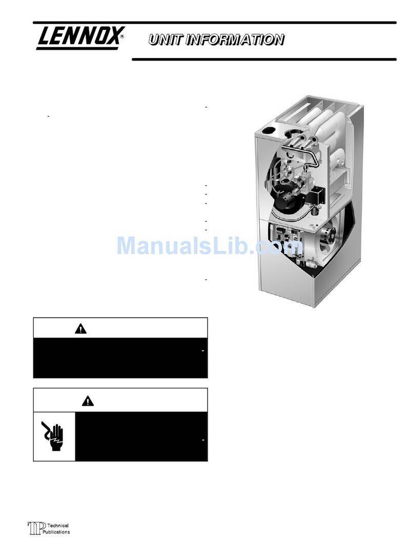
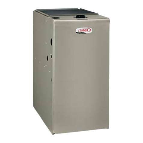
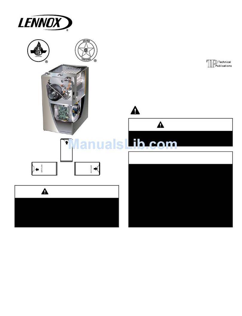
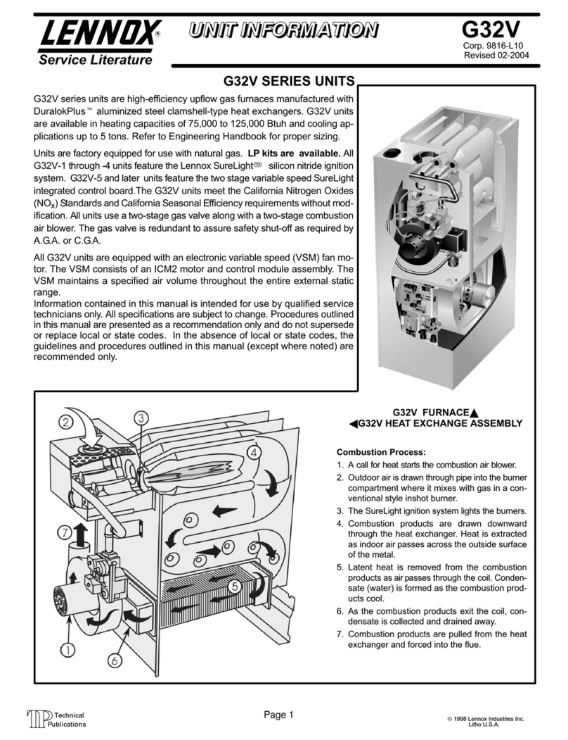
  9. Lennox G43UF SERIES Guide

Lennox G43UF SERIES Guide

0312009
LENNOX)
~
20G4
LennoJ(
IndU&lrioa
Inc.
Oall8l,
Teus,
USA
S04.8Q8M
G43UF
SERIES
SuplllSlldes 02/2004
GAS
FURNACE
f'Jl')jj)
Technlcsl
lll.JPu~lioelions
Litho U.S.A.
Do
notstore or use gasoline or other
flammable vapors and liquids in the
vicinity
of
this
or
any other
ap-
pliance.
Installation and sen/ice must
be
performed by a qualified installer
. '
servIce agency
or
the gas supplier.
WHAT TO DO IF YOU SMELL GAS:
•
Do
not try to light any appliance.
•
Do
not touch any electrical switch; do not
use
any phone in
your
building.
•
leave
the building immediately.
• Immediately call your gas supplier from a
neighbor's phone. Follow the gas supplier's
instructions.
•
If
you cannot reach
your
gas supplier, call
the fire department.
03/09 504,89BM
1111111111111111111111111111111111111111
11111111111111111.11111111111111111111
\~1I11111111
l
'd
6H8
'oN
sa)!flns
I'eJ!u'epa~
J!'el8
~~tS:8
OlOl
'8l'
da
S
'1"'Mlftlzt~_
UPPER
ACCESS
PANEL
COMBUSTION
AIR
PROVING
(PRESSURE)
SWITCH
INTEGRATED
CONTROL
BLOWER
ACCESS
PANEL
DURALOKnI
HEAT
EXCHANGER
ASSEMBLY
GAS
VALVE
AND
MANIFOLD
FLUE:
COLLAR
COMBUSTION
AIR
INDUCER
BLOWER
MOTOR
CONTROL
BOX
FIGURE
1
NOTE -This manu.1
is
the
property
of
the homeowner
lind
must
be
left
with the eqlJlpment user.
This
furnace
is
equipped
With
safety devices that protect
you
and
your property.
If
one
or
more
of
these
devices
is
activated,
furnace
operation will stop. Ifyour
home
is
left
unattended
for
an
exlended period
of
time,
equipment op·
eralion must
be
checked
periodically.
If
this
is not
possible,
the
water supply
to
the
house should
be
shut
off
and
the
pipes
should
be
drained.
This
will
prevent
problems
associ-
ated
with a
NO
HEAT
condition (frozen
pipes,
ele.)
AWARNING
Product
contains
fiberglass
wool.
Distllrbing
the
insulation
in this product during
installation. IlHlintenance,
or
repair will ellpose you
to fiberglass wool.
Breathing
this
may cause
lung
canc~r.
(Fiberglass wool is known to the State of
Cal-
ifornia to cause c;Jncer.)
Fiberglass wool
rnOlY
also cause respiratory, skin.
and
eye
irritation.
To
reducc
~llPOSUre
to
this
substance
or
for further
information,
consult
material
safely
data sheets
available from
~dctress
sllown
helow, or contactyour
supervisor.
Lennox
Indu!itries
Inc.
PO.
Box 799900
Dallas,
TX
75379·9900
Page
2
saJ!AJas
l~J!U~YJa~
J
!~l8
~~~S:8
OlOl
'8l'
da
S
£
'd
6H8
'ol~
'['J',*~""
A
WARNING
NOTICE
Any additions, ch,mges, or
Conyer
sions required in
order for the <tppliancc to satisfactorily meet the ap-
plic<ltion needs must
be
m<lde
I)y a licensed profes-
sional installer
(or
equivalent) lIsing f3ctory-speci.
fied and approved pat1s.
AWARNING
1 -
Keep
the
furnace
area
clear and free ofcombustible
material. gasoline,
and
other flammable
vapors
and
liquidS,
If
it
is
installed
in
an
inSUlated
area,
the
furnace
must
be
kept
free
of insulating
material.
InSUlating
rna.
tarial may
be
combustible,
2 - After
any
heavy
snow,
ice or
frozen
fog
event,
the
fur-
nace
vent
pipes
may
become
restricted.
Always
checK
the
vent
system
and
remove
any
snow
or
ice
that
may
be obstructing
the
plastic intake or
e)(haust
pipes,
3·
DO
NOT
obstruct air flow
to
unit.
Unit must
receive
an
unobstructed
now
of combustion
and
ventilating
air.
DO
NOT
block
or obstruct air
openings
on
the
furnace
Or
air
openings
to
the
area
in
which
the
furnace
is
installed.
Taka
care
to
maintain established clear-
ances
surrounding
the
furnace.
4 -
DO
NOT
store
chlorine
or
fluorine products near unit
or
introduce
these
products
into
the
combustion
air.
These
products
can
cause
furnace corrosion.
S-
DO
NOT
drawreturn aIr from aroom where this fur·
nace, orany other gas appliance
(Ie.,
awater
heat·
er). Is Installed.
When
return
air
is
drawn
from
a
room,
a
negative
pressure
is
created
in
the
room.
Ifa
gas
ap-
pliance
is
operating
in
a
room
with
negative
presSUre,
the
flue
products
can
be
pulled
back
down
the
vent
pipe
and
into
the
room.
This
reverse
flow
of
the
flue
gas
may result
in
incomplete combustion
and
the
formation
of
carbon monoxide
gas.
This
toxic
gas
might
then
be
distributed throughout
the
house
by
the
furnace duct system.
A
WARNING
Yourfurnace is a gas appliance.
It
is
critical
that
the
gas
supplied
to
the
unit
be
completely
burned
'to
avoid
lhe
pro-
duction of
carbon
monoxide
gas.
Complete
combustion
of
the
gas
requires.
but
is
not limited
to.
correct
gas
pressure
and
gas
flow
rate.
adequate combustion,
air.
and
proper
venting.
Exposure to
carbon
monoxide
gas
can
cause
personal
in-
jury
and
even
death
to
all occupants, including
pets,
Any
item
that
is
powered
by
or
gives
off
heat
from
a
combustion
process (including
lawn
mowers. automobiles.
and
fire-
places)
has
the
potential
to
produce
carbon
monOXide
gas.
Because
or
this,
Lennox recommends the use
of
a car-
bon monoxide detector in
your
home, even
if
you
do
not own gas appliances. Reliable detectors
are
available
at
reasonable
retail
prices. Contact
your
Lennox
dealer
for
more
details aboul this investment
in
your safely.
Your
furnace
is
designed
to
meet
standards
sel
by
national
agencies.
and
to operata safely when properly installed
and
maintained, However,
the
unit's performance
can
be
greatly
impacted
by
the
individual installation
and
the
oper·
ating
environment.
It
is
your responsibility
to
ensure
that
this
appliance
is
maintained. Proper
maintenance
is
critical
for
your safety
and
the satisfactory operation of
th6
prod-
uct.
Lennox strongly recommends annual inspection
and maIntenance
of
this appliance. Contact
your
Len-
nox
dealer
for
an
inspection
by
a
licensed
professional
ser-
vice
technician (or equivalent).
Page
3
sn!~JaS
l'e~!u'e4H~
J!'elS
~~SS:8
OlOl
'8l'
da
S
17
'd
6H8
'oN
1~'I!t1!Il'k
'1l",,*I..,
BEFORE
LIGHTING
the untt.
smell
all
around
the
ap-
pliance
area
for
gas.
Be
SUre
to
smell
next
to
the
noor
be-
cause
soma
gas
is
heavier
than
air
and
will
settle
on
the
noor.
The
gas
valve
on
the
G43UF
will
be
equipped
with
a
gas
control
sWitch.
Use
only
your
hand
to
move
the
switch,
Nev-
er
use
tools.
If
the
sWitch
will
not
move
by
hand,
do
not
try
to
repair
it.
Call
a
licensed
professional
service
technician
(or
equivalent).
Force
or
attempted
repair
may
result
in
a
fire
or
explosion.
Placing the
G43UF
furnace into operation:
G43UF
units
are
equipped
with
an
ignition
system.
Do
not
allempt
to
manually
light
burners
On
this
furnace.
Each
time
the
thermostat
calls
for
heat,
the
burners
will
automati-
cally
light.
The
ignitor
does
not
get
hot
when
there
is
no
call
for
heat
on
units
With
this
ignition
system.
Operating the Gas Valve (Figures 2 and
3)
1-
STOP!
Read
the
safety
information
at
the
beginning
of
this
section.
2 -
Set
the
thermostat
to
the
lowest
setting.
3 -
Turn
off
all
electrical
power
to
the
unit.
4·
This
furnace
is
equipped
with
an
ignition
device
which
automatically
lights
the
burners.
Do
not
try
to
light
the
burners
by
hand.
5 -
Remove
the
upper
access
panel.
6·
White
Rodgers
36G
Gas
Valve
-
Move
gas
valve
switch
to
OFF.
See
figure
2
for
the
White
Rodgers
36G
valve.
Honeywell
VR8205
GflS
Valve
-
Move
switch
on
gas
valve
to
OFF.
See
figure 3
for
Honeywell
VR8205
valve.
7 -
Wait
five
minutes
to
clear
out
any
gas.
If
you
then
smell
gas,
STOPI
Immediately
call
your
gas
supplier
from
a
neighbor's
phone.
Follow
the
gas
supplier's
instruc-
tions,
If
you
do
not
smell
gas
go
to
next
step.
S-
White
Rodgers
36G
Gas
Valve
-
Move
gas
valve
switch
to
ON.
See
figure
2
for
the
While
Rodgers
36G
valve.
Honeywell
VR8205
Gas
Valve
-
Move
SWitch
on
gas
valve
to
ON.
See
figure
3
for
Honeywell
VR8205
valve.
White Rodgers
36G
Series Gas Valve
MANIFOLD
PRE88U~E
ADJUSTMENT
SCREW
INLET
t==i_~·PRESSURE
POST
OUTLET
PRESSURE
POST
--."....<kI=::::l:~
GAS
VAlVf:
SHOWN
IN
OFF POSITION
FIGURE
2
Honeywell
VR8205
Series
Gas
Valve
MANIFOLD MANIFOLD
PRESSURE
PRES8UR~
ADJUSTMEN OUTLET
SCREW
GAS VALVE SHOWN IN ON POSITION
FIGURE
J
9 -
Replace
the
upper
access
panel.
.
10
-
Turn
on
all
electrical power
to
to
the
unit.
11
-Selthe thermostat
to
desired setting.
NOTE
-
When
unit
Is
Initially
started.
steps
1
through
11
mayneed
to
be
repeated
to
purge air
from
gas
lina.
12-
If
the
appliance
will
not
operate,
follow
the
section
"Turning
Off
Gas
to
the
Unit"
and
call
your
licensed
pro-
fessIonal
service technician
(or
equivalent).
Turning Off
Gas
to the Unit
1-
Set
the
thermostat
to
the
lowest
setting.
2-
Turn
off
all
electrical
power
to
the
unit
if
service
is
to
be
performed.
3·
RemoVe
the
upper access
panel.
4·
White
Rodgers
36G
Gas
Valve
•
Move
gas
valve
switch
to
OFF.
Honeywell
VR8205
Gas
Valve
-
Move
5witch
on
gas
valve
OFF.
5-
Replace
the
upper
aCcess
panel.
Page
4
SdJ!AJaS
l'e:l!u'e4:l
aWJ!'el8
All G43UF fillers are installed
e)(ternal.
to the unit. Filters
should
be
Inspected monthly. Clean or replace the filters
when necessary to ensure proper furnace operation. Re-
placement filters must be rated for high velocity
alr1low.
Table 1lists recommended filter sizes.
A
filter
must be in place when Ihe unit is operating.
TABLE 1
Furnace Filter Size
Cabinet Width
SIde
Return
Bottom Return
17-1/2"
16
X
25
X 1
(1)
16
X
25
X 1
(1)
21"
16X25X1
(1)
20
X
25
X 1
(1)
24-1/2"
16X25X
1
(2)
24
)(
25
)(
1
(1)
A licensed professional service technician (or eqUivalent)
should inspect the complete system each season (heating
and cooling). The following maintenance procedures
should only
be
conducted by a licensed professional ser-
vice technician (or eqUivalent).
Do
not
attempt
to service
the
unit
in
any
way.
AWARNING
ELECTRICAL SHOCK, FIRE.
OR
EXPLOSION HAZARD.
Annually (before heating season) inspect furnace venting
system, vent cap, heat exchanger, and burners for corro-
sion, deterioration, or deposits
of
debris. Remove any ob-
structions.
Inspect the furnace ror obvious signs
of
deterioration.
Inspect the furnace venting system
to
make sure it
is
in
place, physically sound, and without holes, corrosion. or
blockage.
Vent pipe must
be
clear and free of obstructions and must
slope upward away from the furnace.
Inspect the furnace return air duct connection to ensure
duct
is
sealed to the furnace and terminates outside the
space containing the furnace.
Inspect the physical support
of
the furnace to guarantee
that
It
is sound without sagging, cracks or gaps around
base and it maintains seal between base and support.
Inspect the condensate drain and trap
for
leaks
and
cracks.
The
dr~in
and
trap must also be cleaned and the trap must
be
filled with water.
During a seasonal check the service technician will
con~
duct a combustion analysis. The technician will also in-
spect the indoor blower, burner flames, electrical connec-
tions and the venting system.
810wer
Check the blower wheel for debris
and
clean
if
necessary.
The blower motors are prelubricated for extended bearing
life.
No
further lubrication is needed.
Failure
to
follow
safety warnings eXilctly could result
in
dangerous
operation,
serious
injmy,
death
or
property
damage.
Improper
servicing
could
result
in
dangerous
oper~
tion.
serious
injury.
c1eath,
or
properly
damage.
Before servicing,
disconnect
all electrical
power
to
fUl'I1ace.
When
servicing
controls,
label
<III
wires
prior
to
dis-
connecting. Take cart'
to
reconnect
wires correctly.
Verify
proper
operation
after serVicing.
Venting
System
A WARNING
Asphyxiation
HClzard
The
exhaust
vent
for
this
furnace
must
be Innk·free
and
must
be
securely
connected
to
the furnilce flue
collar
<:It
all times.
For
your
sClfety and
to
ftllfjll
the term::;
of
the limited
warranty, a licensed
professional
service technician
(or
eqUivalent)
Illust
annually
inspect
this
furnace
Jnd
its
vent
system
AWARNING
The
blower
access
panellTlusl
be
securely
in
place
when the
blower
and
burners
are operating.
Gas
fumes.
willet\
could
contam
carbon
monoxide,
can
be
drawn
11110
living space resulting
in
personal
inju-
ry
01
cleCltll
Burner
Flame
A CAUTION
Electrical
1- Check all wiring for loose connections.
2 - Check for the correct voltage at the furnace (furnace
operating).
3 - Check amp-draw
On
the blower motor.
Motor Nameplate
Actual,
_
Page 5
9
'd
6H8
'ON
sa)!AJas
l~)!u~~)a~
J
!~18
~~SS:8
OlOl
'8l'
da
S
"''':&'17&_
,:Q"'".';,l'''
:l~~~~
Ih
Call
your
Lennox
selVice
technician
if
the
unit
will
not
oper-
ate.
Before
calling,
always
check
the
following
to
be
sure
salVice
is
required;
1 -
Check
that
electrical
disconnect
switches
are
ON.
2 -
Check
room
thermostat
for
proper
setting.
3 -
Replace
any
blown
fuses
Or
reset
circuli
breakers.
4 - Gas
valve
should
be
ON.
5 -
Air
filler
should
not
be
plugged,
which
will
limit
air
now.
6·
Is
gas
turned
on
at
meter?
7 -
Is
manual
main
shut-off
valve
open?
Record
the
model
and
serial
number
of
the
furnace.
These
numbers
are
on
the
unit
nameplate,
which
is
located
on
the
blower
deck
below
the
combustion
air
inducer.
Serial
Number
Model
Number
!'Cfliil{
'''.1'
«P'
';"~"
·1
~~'~11"'~
;1\1,'!'~
i~"',
If
you discover any
of
the
following, shut down your
unit,
and
contact a lennolC dealer foran inspection by
a licensed professional service technician (or equIva-
lent).
• If
you
repeatedly
hear
any
new
or
unfamiliar
sounds
while
your
unit
is
operating,
there
may
be
a
problem.
For
example,
poorly
performing
burners
can
produce
unfa-
miliar
noises.
• If
you
smell
any
unusual
odors,
your
unit
may
be
operat-
ing
Improperly.
For
example.
units
can
give
off
unfamil-
iar
odors
if
components
are
required
to
operate
in
ab-
normal
conditionS.
•
Look
(or
Visible
signs
of
a
malfunctioning
unit.
Examples
include
unusual
amounts
of
condensate
on
windows
in-
side
your
house,
vIsibly
burnt
components
or
unusual
dirt
or
rust
accumulations
on
the
vent
pipe
or
in
the
unit.
•
If
you
experience
headache.
nausea,
fatigue,
or
dizzi-
ness,
the
cause
could
be
exposure
to
carbon
monoxide
gas.
This
is
often
misdiagnosed
as
the
flu
because
symptoms
are
similar.
If
you
suffer
from
flU-like
symp-
toms
that
are
exaggerated
at
home,
but
seem
to
sub-
side
while
you
are
away
from
the
house,
exposure
to
carbon
monoxide
could
be
the
cause.
Your
vigilance
may
payoff
in
early
detection
of
a
problem
before
either
personal
injUry
or
property
damage
occurs,
Do
not
hesitate
to
conlact
a
qualified
service
technician
as
an
investment
in
your
well
being.
~,I,:
....
,
';~~:
...
1Il::::
..
:.:"
You
should
expect
a
selVice
technician
to
check
the
follow-
ing
items
during
an
annual
inspection.
Power
to
the
unit
must
be
shut
off
for
the
service
technician's
safety.
Fresh air
grilles
and louvers
(on
the
unit
and
in
the
room
Where
the
furnace
is
installed) -
Must
be
open
and
unob-
structed
to
provide
combustion
air.
Burners-
Must
be
inspected
for
rust,
dirt,
or
signs
of
water.
Vent pipe -
Must
be
inspected
for
signs
of
water,
damaged
or
sagging
pipe,
or
disconnected
joints.
Unit appearance -
Must
be
inspected
for
rust,
dirt,
signs
of
waler,
burnt
or
damaged
wires.
or
components.
Blower access door-
Must
be
properly
in
place
and
pro-
vide
a
seal
between
the
return
air
and
the
room
where
the
furnace
is
installed.
Return air duct -Musl
be
properly
attached
and
proVide
an
air
seal
to
the
unit.
operating performance. Unit
must
be
observed
during
operation
to
tnonilor
proper
performance
of
the
unit
and
the
vent
system.
Combustion
gase8
-
Flue
products
must
be
analyzed
and
compared
to
the
unit
speclflcations.
Problems
detected
during
Ihe
inspection
may
make
it
nec-
essary
to
temporarily
shut
down
the
furnace
unlil
the
Items
can
be
repaired
or
replaced.
Pay
attention
to
your furnace.
Situations
can
arise
be-
tween
annual
fumace
inspections
that
may
result
in
unsafe
operation.
For
instance.
items
innocently
stored
ne>rt
to
the
fumace
may
obstruct
the
combustion
air
supply.
This
could
cause
incomplete
combustion
and
the
production
01
car-
bon
monOXide
gas.
Page
6
sa)!hJaS
l'eJ!u'e4H~
J!'el8
L .d
6HS
'oN
.,.n£lt's:tst~
..
The
following
repair
paris
are
available
through
Lennox
dealers.
When
ordering
parts,
include
the
complete
furnace
model
number
listed
on
the
CSA
International
nameplate
-
Example:
G43UF-24B-045-2.
All service must
be
done byalicensed
professional Installer (or equivalent), 8 service agency, or the gas supplier.
Cabinet Parts
Upper
access
panel
Blower
access
panel
Top
Cap
Control Panel Parts
Transformer
Integrated
control
Door
interlock
switch
Blower Parts
Blower
wheel
Motor
Motor
mounting
frame
Motor
capacitor
Blower
housing
cutoff
plate
Heating Parts
Flame
Sensor
Heat
exchanger
assembly
Gas
manifold
Combustion
air
inducer
Gas
valve
Main
burner
cluster
Main
burner
orifices
Pressure
switch
Ignitor
Primary
limil
control
Secondary
limit
Flame
rollout
switches
Combustion
air
inducer auxiliary
limit
Page
7
Sa)!AJ~S
IF)!UF4H~
)!FI8
~VSS:8
alae
'Sl'das
8
'd
6VL8
'ON
[Jj)[f!)[fif
rmJ~4\
iJfWjffJ
LENNOX)
13ACX
Corp,
0612·L2
Revised
AuguBl11.
2010
Service
Literature
411
l.OUVERED
NON·LOUVERED
A WARNING
ImprOPt'r
im;lallalioll, adjustment,
alt~ratl()n.
i;f:;rvil.:\:
or
mamtenanr.p.
can
Cllll~;e
pcr:;oll.:llilljury. loss
olliff!,
Of
dam3gA tn properly
In~~IClII;1tion
;.lClI.1
~;(~rVICl)
IlIllst
be
perform8d
by
;'1
liC;;;r1~;'.ic.1
prnff:i;$iIHltll
in~;I'.lllcr
(or
equivalent) or
;'\
~8rVIr:e
;.I!Jt.~!lC.:Y.
A IMPORTANT
ThiS IlIlil !nu'.;l
be
IllEllclled
wiltl
311
incloClI r:od
m;
specified
in
LAnnnx
EIIU1f1l,l,:,nnn
H~lndl)l)ok.
Coils
pr
oviou31y
c:llarged willi
HCFC
22
rt'1I,1~.;1
he
flushed.
TABLE OF CONTENTS
Model
Number
Identification "
Typical
Serial
Number Idenlification
Specifications ,
Electrical
Data
Unit
Dimensions , , . ,
Typical
Unit
Parts
Arrangement
Operating Gauge Set
and
Service
Valves
Unit
Placement, . ' , . '
Removing
and
Installing Louvers ,
Newor Replacement Line
Set
..
,
,.,.,
2
,, , 2
, ,., .. ... 2
"
Brazing Connections ,. . .. . .. ..
..
.
..
..
Flushing Line
Set
and
Indoor
Coil
...
,,
...
,
,.
15
Installing Indoor Metering Device. . . . ... ..
..
..
.
..
16
Leak
Test
Line
Set
and
Indoor Coil, ,
..
, ..
..
17
Evacuating Line Sel
and
IMoor
Coil
,
,.,..
18
Electrical Connections " ,
"",
19
Servicing Unit
Void
of Charge ,
21
Unit
Start-Up, ,
..
,.. , ., , ,,. , ,
21
System
Refrigerant , ., ,
..
, '
..
,. , ,.. .
..
21
System
Operation
,.",
,
..
,."
, " 28
Maintenance , . , ,
..
,, . ,
..
,, ' ,
..
,,
,.
28
start·Up
and
Perlormance Checklist
,.,
..
,
...
29
Sequence ofOperations
....
,. ,
....
,. , , ,
..
,
,.
30
13ACX
Air Conditioners. which will
also
be
referred
to
in
this
instruction 8S
the
outdoor
unit,
uses
HFC-4
1
OA
refrigerant. This outdoor unit must
be
installed with a
matching indoor unit
and
line
set
8S
outlined
In
the
Lennox
13ACX
Engineering
Handbook.
This
outdoor unitls designed for use in
systems
that use
one
of
the
following refrigerant metering
devices:
Thermal
expansion valve
(TXV)
•
Fixed
orifice
A IMPORTANT
Thf~
Clc"ln Air Act or 1
mJO
bans
!lle
mlAnliol);'ll velllirJ(j {If
rdllt~",ranl
(CF(>.;. HCFCs and HI Cs)
<IS
of July
1,
1992.
Approved rnelho<b
r)r
r~(;(Iv(';ry.
rt.'cycling or
rc:c
l
ail11l1lg
mw;1
he followed.
1-11l8S
ElIl(J/Qr
incarceration
may
t>~
II~vwl.1
for
nOllcompll.:mce.
..
,.....
4
,. ,.. , .
..
6
,
..
,...
7
, ' . .
..
7
,,
..
,....
..
9
10
'"
11
13
Page
1
6
'd
6VLB
'ON
UFlftJllllb
"("t,*~-a,
;"··,*Is:el$t~.
:=]
1 X-024 -
t-13
Nominal SEER
~
T Minar
Revilion
NumberD
Voltage
Unit
Type 230;; 208/230V·1phase-60h:z
AC
;;
Air Conditioner Cooling Cepaclty -
Tons
018'"
1.5
Refrlgeranl-----------l
024;;
2
030'"
2.5
X'" R-410A
036'"
3
042;;3.5
048
"'4
060"
5
location
Code
19'"
Saltillo,
Mellic_----'
58
=Marshalltown.
IA
L
'(or
6)
Dlgl'
"",que
"urn"'"
Year CodI Month
Code
06;;
2008 A'" January
09'"
2009 B'" February
10'"
2010
....J C"'March
Model
Number
Page 2
ol
'd
6PLB
'ON
.,
""",,*~_1'
iu,I'mles):.
Un~
OuldoorFan
Model
Nl,I\l1ber
13ACX-060·230-12
~~1:
.'
!t~
..
,.
.n
:';'
.
SOl,lnd
RIIUnQ
Number
(dB~
Number
01
Blada;
Diameler
-Inches.
1
Tesllild
according
to
AHRI
Stundard
270·2006
test
GOn(lilions.
2
Refrigerant
chargo
$ulficianl
for
15
feel
length
of
refrillllranl
~nlIs.
Page
3
13ACXSERIES
II
'd
6VL8
'oN
,
.[tI'ItI~1a,
208l230V-tlo
Hl:-1
Ph
Un~
ComJnlSsor
CoroilnsBr
Fan
Model
Number
Maximum
Over-
current
Froleclion
(amps)'
Minimum
Cltcully
Ampaci1r
Re1&dLoad
Amps
(RLA)
locked
Rotar
Amps
(LRA)
MolorHP
Nominal
RPM
Full
Load
Locked
Rolor
Amps
(FLA)
Amps
(LRA)
2081230V-130
Hz-1
Ph
Unn
Compr8!lsor
Cood9nser
Fan
Model
Number
Maximum
Over-
currant
PrQ\llc~on
(amps)'
=,.,..."."".""""",,,,,,,,,,,,,,,,,,,,,,,,,,,:1=:::
Minimum
Circuity
Ampllcilr RllledLood
Amps
(RLA)
lockad
Rotor
Amps
(LRA)
MolorH~
Nominal
RPM
Full
Lolld
Locked
Rotor
Amps
(FLA)
Amps
(LRA)
208l230V-130
Hz-1
Ph
Compressor
Cond9nser
Fan
MOdel
Number
Maximum
Over-
currenl
Frotection
(amps)'
Minimum
Circuily
Ampacilr
Rated
Load
Amps
(RLA)
locked
Rolor
Amps
(LRA)
MolorHP
Nominal
RPM
Fl1l1
Loao
Locked
Rotor
Amps
(FLA)
Amps
(LRA)
2081230V-50
Hz-1
Ph
Un~
Condenser
Fan
Model
Number
Maximum
Over-
currenl
F'rotllclion
(amps)'
=""""..m"""",,,,,
Minimum
Clrcully
Ampaclly2
Rated
l...08d
Amps
(RLA)
L.ocked
Rolor
Amps
(lRA) MolorHP NomInal
RPM
Full
Load
Locked
Rotor
Amps
(FLA)
Amps
(LRA)
Page
4
vW9S:8
OlOl
'8l'
da
S
II
'd
6H8
'ON
a
'[1"11'-'"
a"'SA'tC170.
20el230V-60
Hz-l
Ph
Unl
CompresSOf
~Fan
Model
Numbsr
Maximum
Over-
current
ProtecUon
(limps)'
=='l':'hI=
Minimum
Circuity
Ampacity2
Rllled
Load
Amps
(RLAl
Locked
Rotor
Amps
(LRA)
MolorHP
Nominal
RPM
Full
Load
Locked
Rolor
Amps
(FLA)
Amps
(LRA)
20B/230V-110
Hz-'
Ph
Model
Number
Minimum
Ci~uity
AmpacitYZ
CompresSOf
Rated
Load
Amps
(RLA)
Locked
ReIDr
Amps
(LRA)
MotorHP
Corden8erFan
Nominal
RPM
Full
Load
Amp,
(FLA)
Locked
Rotor
Amps
(LRA)
201l/230V-60
Hz-'
Ph
Un~
Coo1p"6sSOf
Condenslll'
F:ln
Model
Number
Maximum
OVllr-
curronl
Pro\ec~on
(:lmp6)l
MinImum
Circuity
Ampacitil
Reled
Load
Amps
(RLA)
Locked
Rotor
AmP6
(LRA)
MatotHP Nominal
RPM
Full
Load
loOked
Rotor
Amps
(fLAl
Amps
(LRA)
,
HACR
lyps
clrl;<,lil
breaker
or
fuss.
2
Rarer
Ie Neliomll or
Canadian
Electrlcal
Coda
manuel
10
dlltermine
wire,
fuse
and
disconnect
,,'zlil
"'Guiremenls,
PageS
13ACl(
SERIES
£I
'd
6H8
'Ol~
"
"["',,*~-jf'
,... A
,---
A -I
·1
I
OUTDOOR
~DISCHARGE
AIR
COILFAN~
L.-::.
I
'--
COMPRESSOR
B
sucnON
ANO
LIQUID
LINE
CONNECTION
"'l
OPTIONoAL
UNIT
6TANDOff
KIT
(4)
__
.~~~===~~;=;J
E~
(fiELD
INSTALLED)
___
Page 6
VNLS:S
OlOl
'Sl'daS
tl
'd
6HS
'ol~
a,,·Wt'ttf6.
DISCi"IARGE
LINE
CONTROL
WIRE
LOOP
NOTE
-
PLUMBING
LAYO\JT
AND
COMPRESSOR
TYPE
MAY
VAFN
SLIGHTLY
COMPRESSOR
HARNESS
OUTDOOR
COIL
SUCTION
LINE
SERVICE
HIGH
PRESSURE
$WITCI1
(S~l
L10UIO
LINE
6ERVICE
VALVE
COMPRESSOR
IlETWI:I:N
MODEL
SIZES.
VALVE
When servicing or repairing HVAC components, ensure
the fasteners are appropriately tightened.
Table
1provides
torque values for fasteners.
Table 1. Torque Requirements
Recommended Torque
TORQUE REQUIREMENTS
When servicing or repairing heating, ventilating, and air
conditioning components, ensure the fasteners are
appropriately tightened, Table 1 lists torque values for
fasteners,
USING MANIFOLD GAUGE SET
When checking
"the
system charge, only use a manifold
gauge set that features low loss anti-blow back fillings.
Manifold gauge set used with
HFC-410A
refrigerant
systems must
be
capable
of
handling the higher system
operating pressures. The gauges should be rated for use
With
pressures
of
0 - 800 psig on the high side and a
loW
side
of
3D"
vacuum
to
250
psig with dampened speed to
500
psi. Gauge hoses
must
be rated for use at up to
800
psig of pressure with a
4000
psig burst rating.
OPERATING
SERVICE
VALVES
The liquid and vapor line service valves are
lJsed
for
removing refrigerant, flushing, leak testing, evacuating,
checking charge and charging,
Each valve is equipped with a service port which has a
factory-installed valve stem. Figure 1 provides informatIon
on how
to
access and operating both angle and
ball
service
valves.
Page 7
IJACl<
SERIES
Sl
'd
6VL8
'oN
1
tl·"W!It'a,
SERVICE
VALVES
ANGLE
AND
BALL
Operating
Angle
Type
Service
Valve:
1,
Remove
stem
cap
with
an
~teIy
sizlld
wrench.
2.
Use
a
service
wrench
wilh
a
hex-head
elC1eneion
(3/16'
for
liquid
line
velve
ei%6118nd
5116"
for
vapor
line
vllive
sizes)
to
back
Ihe
Glom
Ollt
counterclockwise
at:
far A&
It
will
go.
(VALVE
STEM
SHOWN
OPEN)
INSEFrr
I1EX
WRENCH
HERE
TO
INllOOR -1-"":>"';;:-:;;os:---11
UNIT
SERVICE
PORT
CORE
TO
OUTDOOR
UNIT
ANOL£TYPE
SERVICE
VALVE
(BACI<-llEATED
OPENED)
When
seollce
vBlve
is OPEN.
lhe
eervice
port
is
open
to
linE
liel.
indoor
and
outdoor
uni\.
STEM
CAP
ANOLE·rfPE
SERVICE
VALliE
(fRONT
-SEATED
CLOSED)
WHEN
6ERVICE
VN..VE
16
CLOSED.
THE
5ERVIC~
PORT
16
OPEN
TO
THE
LINE
SET
AND
INDOOR
UNIT.
Operating
Ball
Type
Service
Valve:
1.
Remove
slem
cap
wiUI
an
apprtlIlIial8l)'
sized
wrench.
2.
Use
sn
appropriately
sized
wrenched
10
open.
To
open
valve,
roale
£tem
oounlerdocl<wlse
90'.
To
close
rotale
stem
e1OCkWlOB
90'.
1/&
TURN
1/1HUIIH
Wilh
Torque
Wrench:
!=Inger
IighIen
and
then
lorque
cap
p9I'
~
1.
WIthout
Torque
Wrench:
Flnger
Ifghl-
en
ar1d
use
an
approprlalely sized
wrench
10
lum
an
add1tl0l'l1l11/12
tum
clockwise.
•
Wilh
lorque
wrench;
Finger
tighten
and
lorque
cep
per
table
1.
• Wilhoul
torque
wranch:
Finger
tighten
and
\l6e
an
appropliolely
sized
wrench
10
lum
an
addl~0l'lal1/8
lum
clockwise.
•
Reinstall Stem Cap:
Stem
cap
prQtecl6
Ihe
valve
slem
from
damage
and
serve&
all
the
prlmary
S"'i11.
Repla06
the
stem
cap
and
tighten
as
follCM'S:
To
Access
SeNice Port:
A
6ervice
port
cap
ptotects
Ihe
service
port
QC)re
from
conlamlnallon
and
serves
as
Ihe
primal)'
leak
seal.
1.
Remove
servico
port
alP
with
an
appropiBteIy
sized
wrendl.
2.
Connect
gauge
set
10
&8!V~
pc;lrt,
3.
~
IeliUng
is
CXlIT1p1elAld.
replaoe
s6IVice
pori cap
and
tighten
as
lDliaMl:
BAL~(SHOWN
CLOSED)
VALVE
/STEM
TO
OUTDOOR
UNIT
SERVICE
POAT
SERViCE
PORT
CORE
SERVICE
PORT
CAP
TO
OPEN
ROTATE
STEM
COUNTERCLOCKWISE
90',
TO
CLOSI:
ROTATE
STEM
CLOCKWISE
90'.
NOTE
- A
label
with
&pecific
Iorque requlremenb
may
be
amxEld
to
the
slem
cap
If
Ihe
label
is
present,
use
the
speclnBd
torque.
Figure
1.
Angle lind Ball Service Valves
Page
8
~WSS:S
OlOl
'Sl'daS
9l
'd
6VL8
'Ol~
~I
'i""l$n'f"7)~-
,,·""*
....
15'
MINIMUM
CLEARANCE
CLEARANCE
ON
ALL
SIDES
-INCHES
(MILLIMETERS)
ABOVE
UNIT
NOTES:
•
CLef-RANC!:
TO
ONe
OF
'HI:
OTHER
THREe
Sloes
MUS'!'
BE
36
INCHES
(914MM)
.
•
CLEARANCE
TO
ONE
OF
THE
REMAINING
lWO
SIDES
MAY
BE
12
INCHES
(305MM)
AND
THE
FINAL
SIDE
MAY
8E 6
INCHI:S
(lS2MM),
MINIMUM
CLEARANCE
BETWEEN
TWO
UNITS
ACCESSPANEL~:I!!!I!!!!!!!i!IIl~
LINE
SET
CONNECTIONS
Figure
2.
Installation
ClearancGs
DETAIL
A
INSTALL
UNIT
AWAY
II
FROMWINDOWS
~"
" I
"'-
..
L
-------
-
--
'"
DETAIL
B
GROUNO
L~VEL
MOU"TING
SLAB
BUILDING
STRUCTURE
Install
unit
level
or.
if
on
a
slope,
malnlaln
slope
tolerance
of
2
degreQs
(or
2
Inches
per
5
feet
[50
mm
per
1.5
mllaW8Y
rrom
building
structure.
DISC~RGE
AIR
11"
Figure
3.
Placement, and Slab
Mounting
POSITIONING CONSIOERATIONS
Consider
the
following when positioning the unit:
• Some localities are adopting sound ordinances based
on the unit's sound level registered from the adjacent
A CAUTION property. not from the installation property. Install the
unit as far as possible from the properly line.
• When possible,
do
not
install the unit directly outside
............
a window. Glass has a very high level of sound
1!iT.'lI'~~rr;:;;o;=;;;;;m~;;;;;;;;;;mr.;;;;;""""""","",~II'".ml:I'""",",""""""""""""
transmission. For proper placement
of
unit
in
relation
to a
window
see the prOVided illustration in figure
3.
Detail
A.
Page
9
13ACX
SERIES
Ll
'd
6VL8
'ON
~V8S:8
OlOl
'8l'
da
S
• ·'!"mlr'fir;
..
PLACING
UNIT
ON
SLAB
When
installing unit
at
grade
level.
the top
of
the
slab
should
be
high
enough
above grade
so
thai water
from
higher
ground
will
not collect around
the
unit.
The
slab
should
have
a
slope
tolerance
as
described
In
figure
3,
Detail
B.
ROOF
MOUNTING
Ins1all
the
unit
a
minimum
of6
inches
(152
mm)
above
the
roof
sUrface
to
avoid
ice
build-up around
the
unit.
Locate
the
unit
above
a
load
bearing wall
or
area
of
the
roof that
can
adequately
support
the
unit.
Consult
local
codes
for
rooftop
applications.
If
unit
coil
cannot
be
moun1ed
away
from
prevailing
winter
winds,
a
wind
barrier
should
be
constructed.
Size
barrier
at
When
remol/lng
Ihll
unll
panels.
Remove
panel
A Ii",t.
Ulen
B.
C
and
least the
same
height
and
width
as
outdoor
unit.
Mount
barrier
24
inches
(610
mm)
from
the
sides
ofthe
unit
in
the
direction
of
prevailing
winds.
PANElC
finally
0,
When
leinsl8l1ing
panels,
Illl/llrseUlatol'dllr sllirting
w1Ul
panel
0,
C,
8
8nr:l
finally
A.
REMOVAL
STEP
1
TO
REMOVE
PANEL,
REMOVE
MOUNTING
SCREWS
SECURING
PANEL
TO
THE
UNIT.
STEP
2
SLIGHTLY
LIFT
PANEL
A
IN
ORDER
TO
CLEAR
SIDE
LIPS
OF
PANeL
FROM
BASE
OF
UNIT.
STEP
3
TILT
PANEL
OUT
SLIGHTL'I'
ANO
PULL
DOWNWARD
TO
REMOVE,
REPEAT
STl:pS
1,
;/
AND
3
TO
RI:MOVe
PANeLS
B.
c
AND
FINA~LY
O.
PANEl.
A
PANEL
A
INSTALLATION
STEP
1
TOP
CAP
STARTING
WITH
PANEL
D,
INSERT
PANEL
UNDER
UNIT
TOP
CAP
LIP
AND
LIFT
SllGI1TL'I'
10
CLI:AR
SIDE
LIP
OF
PANeL
fROM
BASE.
STEP
2
Move
PANEL
IN
TOWARDS
UNIT.
ALIGN
LEFTIRIGHT
SIDE
LIPS
OF
PANEL
WITH
GROOVE
INSERTS
ALONG
LEFT/RIGHT
SIDE
OF
UNIT.
SIDE
GROOVE
STEP
3
SECURE
PANEL.
WITH
MOuNTING
SCREWS,
REPEAT
STEPS
1
AND
2
TO
INSTALL
PANELS
CO
D
AND
FINALLYA-.,
PANEL
0
Figure
4.
Louvers
Page
10
SI
'd
6HS
'Ol~
~WSS:S
OlOl
'Sl'daS
.,"'RfJfll'$)s"
:1
This
section
provides
information
on
new
installation
or
replacement
of
existing
line sel. If a
new
or
replacement
line
set
is
not
required,
then
proceed
to
Brazing
Connections
on
page
14.
Table
2.
Refrigerant Line Set (MM)
Valve Field
Size
Recommendad
Line
Set
Connections
Model Liquid Sudlon Liquid L15
Line Suction
Line
Une
LlneSeb
.(118
U'"
L15~1
3/8
In.
3/4111.
3/4
In.
3/Bin
.(124
151t
-50ft
(10mm) (19mm) (10mm) (19mm) (4.6m
-15
m)
.030
.038
L.1S·65
318
In.
318111.
7/8
in
7/8in
.{I42
151t.-501\.
(10mm) (22mm) (10mm) (22mm)
.{I48
(4.6m-15m)
3/8
In.
3/8
in.
1·1/8
In.
1-1/8
in.
field
.(160
(29mm)
(10mm) (10mm) (29mm)
Fabl'lcllted
NOTE
-
Some
applicalions
may
required
a
nald
provided
7/8"
to
1-1/6"
adapter
NOTE"
When
installing refrlgenmt lines longer than
50
feet,
see
the
Lennox Refrigerant Piping Design and
Fabrication Guidelines,
CORP.
9351-L9, or contact
Lenno~
Technical Support Product Applications for
assistance.
If
refrigerant
lines
are
routed
through
a
wall.
seal
and
isolate
the
opening
so
vibration
is
not
transmilted
to
the
building.
Pay
close
altention
to
line set isolation
during
installation
of
any
HVAC
system.
When
properly
isolated
from
building struclures (walls, ceilings.
floors),
the
refrigerant
lines
will
not
create
unnecessary
vibration
and
subsequent
sounds.
Also.
consider
the
following
when
placing
and
Installing
a
high-efficiency
air
conditioneL
Field
refrigerant
piping
consists
of
liquid
and
suction
lines
from
the
outdoor
unit
(braze
connections)
to
the
indoor
unit
COil
(nare
or
braze
connections),
Use
Lennox
L
15
(braze.
non-flare)
series
line
set,
or
use
field-fabricated
refrigerant
lines
as
listed
in
Table
2.
The
compressor
is
charged
with
sufficient
Polyol
ester
011
for
line
set
lengths
up
to
50
feet.
Recommend
adding
Oil
to
system
based
on
the
amount ofrefrigerant
charge
in
the
system.
No
need
to
add
oil
in
system
with
20
pounds
of
refrigeranf
or
less.
For
systems
over 20 pounds·
add
one
ounce
of
every
five
pounds of refrigerant.
Recommended
topping-off
POE
oils
are
Mobil
EAL
ARCTIC
22
CC
or ICI
EMKARATE""
RL32CF,
To
obtain
the
correct Information
from
Lennox,
be
sure
to
communicate
the
following
points:
•
Model
(13ACX)
and
size of unit
(e.g.
-OSO),
•
Line
set
diameters
for
the
unit
being
installed
as
listed
;h
table
2
and
total
length
of
installation.
•
Number
of
elbows
and
if
there
is
a
rise
or
drop
of
the
piping.
MATCHING
WITH
NEW
OR
EXISTING
INDOOR
COIL
AND
LINE
SET
The
RFC1-metering
line
consisted
of
a
small
bore
copper
line
that
ran
from
condenser
to
evaporator
coil.
Refrigerant
was
metered
into
the
evaporator
by
ulilizing
temperature/pressure
evaporation
effects
on
refrigerant
In
the
small
RFC
line.
The
length
and
bore
of
the
RFC
line
corresponded
to
the
size
of
cooling
unit.
If
the
13ACX
is
being
used
with
either
a
new
or
existing
indoor
coil
Which
is
equipped
with
a
liquid
line
which
served
as
a
metering
device
(RFCI),
the
liquid
line
must
be
replaced
prior
to
the
installation
of
the
13ACX
unit.
Typically
a
liquid
line
used
to
meter
flow
is
1/4"
in
diameter
and
copper.
LIQUID
LINE FilTER
DRIER
INSTALLATION
The
filter
drier
(one
is
shipped
with
each
13ACX
unit)
must
be
field
installed
In
the
liquid
line
between
the
oUldoor
unit's
liquid
line
service
valve
and
the
Indoor coil's
metering
device
(fixed
orifice
or
TXV)
as
illustrated
in
figure
5.
This
filter drier must
be
installed
to
ensure
a
clean,
moisture-free
system.
Failure
to
install
the
filter drier
will
void
the
warranty.
A replacement filter drier
Is
available
from
Lennox.
See
Brazing Conn6cfions
on
page
7
for
special
procedures
on
brazing filter drier
connections
to
the
liqUid
line.
BRAZE
CONNECTION
POINTS
"'".~
~!
SERVICE
VALVE
LUE
LIQUID
LINE
fiLTER
DillER
OutDOOR
UNIT
Figure
5.
Typical
Liquid
LIne Filter Drier
InstallatIon
A IMPORTANT
If
tI'II~;
Ul1itlS
beinq
m;'JlcIH"!d
with
Eln
approv~(llirw
set
or
1I1(loor
lmit
C(,i1
which
was
previuw.;ly
chmqed
with
rnlll(Hal oil,
or
if
il
I~;
bcinq
lllatclH~rl
wilh
a
coil
whietl
Weii;
IlIwluf<lctured
I)Hf
...
)/~
.J<Hlumy
<)f
199:-1, tile
Gail
.:ml"1
i1r'1<::
sclll1u~·t
be
tllJf;lH'!d prior
10
IIlstall8linn.
Take
care
10
erlqlly
all c:xislillq trapi;. P(llyol
ester
(POE) oils
me
used
in LerllllJX
L1llits
Cll;:Jfg~d
With
HrC·410A
(efri!Jcr':lnl.
~e~;il"JIJ:·11
rnilleral
Oil
can
:.ld
8S
an
ill~.;I.i1Clt(or.
prewmliliU
proper
1'le8t
t"'lm;fp,r. It
c<ln
also
clog
lIh.l
exp<lllsion
(Jp.vil";r::,
'.Hld
reduce
the
:,;y~;lern
perlorrn;Hl';C
ulld
capaCity.
Fallure to propvrl)/ f1usl) tilt'!
system
per tI,e
instruction:;
h8!<.lW will VOid
Hle
warranty.
Page
11
1SACX
SERIES
6l
'd
V1~8S:8
OlOl
'8l'
da
S
""''1.-..,
LInt
Stt
Ilohllllon -
The
following
illustrations
llre
eKamples
of
propelr
rQfrlgelranlllne
sal
isohllion:
REFRIGERANT
LINE
SET
-
INSTALLING
FROM
VERTICAL
TO
HORIZONTAL
REFRIGERANT
LINE
SET
-
TRANSITION
VER°rlCAL
RUNS
(NEW
CONSTRUCTION
SHOWN)
NOTE
-
Insulale
liquid
line
when
It
Is
rouled
through
areEls
'whera
the
surrounding
ambienl
lemperature
could
become
higher
than
Il'Ill
ANCHORED
HEAW
NYLON
temperatureof
the
liquid
5ne
or
when
pressure
drop
Is
equal
10
or
grBillI:Jr
WIRE
TIE
OR
AUTOMOTIVE
AUTOMOTIVE
than
20
psi!).
MUFfLER·TYPE
HANGER
MUfFLER·TYPE
HANGER
HHH::1r---
WIRE
TIE
r~tRI_1't-
\
OUTSIDE
WALL
LIQUID
LINE
I
IN61DE
WALL
STRAP
STRAP
LIQUID
LINe
TO
NON-cORROSIVE
VAPOf\
LINE
METAL
SLEEVE
WIRE
TIE
b
-trIH-+t~
WOOD
BLOCK
VAPOR
LINE·
WRAPPED
Hi'lII-H-
WIRE
TIE
INARMAfLEX
~VTSTRAP
REFRIGERANT
LINE
SET
-INSTALLING
HORIZONTAL
RUNS
\
SLEEvl;
To
hang
line
sel
from
jell$!
Or
rafter,
use
eilher
metal
strapping
malllrial
or
anct10red
heavy
nylon
wire
liBG.
\
TAPe
OR
WIRE
TIE
FLOOR
JOIST
OR
ROOF
RAFTER
""-LIQUID
LINE
WALL
STUD
STRAp
THE
VAPOR
LINE
10
THE
JOIST
OR
RAFTER
AT
8
FEET
(2.~3
MEl'e:RS)
INTERVALS
THEN
STRAP
THE
LIQUID
LINE
TO
THE
VAPOR
LINE.
NOTE
-
Similar
Ins
lallation
praclices
should
be
used
If
line
sill
Is
\0
bCllnstalled
an
6llIeJior
of
oulllidll
wall.
Figure
6.
Line Set Installation
Page
12
ol
'd
6HB
'Ol~
~WBS:B
OlOl
'Bl'daS
It:
AWARNING
r--------
r-----
AWARNING
A
IMPORTANT
Gr.lIH1ccl
D<lurlG
set
low
pressure
sicle to
varJOf
line
service
vC1lve
and
repe;~1
pw(;edurp.
~;!(Irling
ot
p,~r;~<JI';'lph
4
rur
!)[lx/in!) Ihl.' liquid
linG
to service port
v:1Ive.
IIIfiIiiiIII
IIIfiIiiiIII
1"-
__
AWARNING
rire,
Explt)f;IOn ;Hld
Pcr~jonal
Safely
H<lL8Id.
F8ill.lr8 to follow tillS wsrnlng could
I
Hf;tJ((
in
d:lIll(l!)C,
pcrc;onal injury
or
d~;1ttl
Never
LISP.
nx\,g~n
10
prl:'~~l.Irir.e
or
purfJC
rcfriqeratioll
lines Oxygen,
wh~f1
eXr)(.l~i::,.l
to
CI
spClrl<
or
open
(I;HlII),
CUll
CllWje
(lalll8qe
by
fire
allfJ/or
an
explOSion, Itllll
CI.llIld
rc':'ult
in perf,on,,1 injury
or
dealh.
Page
13
13/1CX
SERIES
II
'd
6VL8
'Ol~

Other manuals for G43UF SERIES

6

Other Lennox Furnace manuals

Lennox Elite series User manual

Lennox

Lennox Elite series User manual

Lennox Allied Air A95UH1D User manual

Lennox

Lennox Allied Air A95UH1D User manual

Lennox G60DF(X) Series User manual

Lennox

Lennox G60DF(X) Series User manual

Lennox EL196UH030XE24B Owner's manual

Lennox

Lennox EL196UH030XE24B Owner's manual

Lennox ML180DFE SERIES Installation and operation manual

Lennox

Lennox ML180DFE SERIES Installation and operation manual

Lennox Elite series User manual

Lennox

Lennox Elite series User manual

Lennox EL196DFE Series Guide

Lennox

Lennox EL196DFE Series Guide

Lennox MERIT ML180DFE User manual

Lennox

Lennox MERIT ML180DFE User manual

Lennox EL280UHE Service manual

Lennox

Lennox EL280UHE Service manual

Lennox SIGNATURE SLO185BV Series User manual

Lennox

Lennox SIGNATURE SLO185BV Series User manual

Lennox Allied Air A80DF User manual

Lennox

Lennox Allied Air A80DF User manual

Lennox G23 Series Guide

Lennox

Lennox G23 Series Guide

Lennox GSR14 User manual

Lennox

Lennox GSR14 User manual

Lennox EL195DF SERIES User manual

Lennox

Lennox EL195DF SERIES User manual

Lennox Signature G60UHV36A-070 User manual

Lennox

Lennox Signature G60UHV36A-070 User manual

Lennox G32V SERIES Guide

Lennox

Lennox G32V SERIES Guide

Lennox EL296DFE Series User manual

Lennox

Lennox EL296DFE Series User manual

Lennox G51 User manual

Lennox

Lennox G51 User manual

Lennox ML180UHV Guide

Lennox

Lennox ML180UHV Guide

Lennox HART-1445-26 Assembly instructions

Lennox

Lennox HART-1445-26 Assembly instructions

Lennox ML296UHV(X) Series User manual

Lennox

Lennox ML296UHV(X) Series User manual

Lennox ML180DF045P24A User manual

Lennox

Lennox ML180DF045P24A User manual

Lennox G60UHV(X) series Guide

Lennox

Lennox G60UHV(X) series Guide

Lennox Merit ML296UHV Series Installation and operation manual

Lennox

Lennox Merit ML296UHV Series Installation and operation manual

Popular Furnace manuals by other brands

Carrier 58SX040-IBC Application data

Carrier

Carrier 58SX040-IBC Application data

Rheem 96V Series installation instructions

Rheem

Rheem 96V Series installation instructions

United States Stove HOTBLAST 1200G owner's manual

United States Stove

United States Stove HOTBLAST 1200G owner's manual

KOB KOB PYRTEC SERIES Assembly and installation instructions

KOB

KOB KOB PYRTEC SERIES Assembly and installation instructions

VERDER CARBOLITE GERO AAF 11/3 Installation, operation and maintenance instructions

VERDER

VERDER CARBOLITE GERO AAF 11/3 Installation, operation and maintenance instructions

Carrier F80VTL Installation, start-up, operating and service and maintenance instructions

Carrier

Carrier F80VTL Installation, start-up, operating and service and maintenance instructions

Haier GE NF80DS installation instructions

Haier

Haier GE NF80DS installation instructions

Carrier 394GAD installation instructions

Carrier

Carrier 394GAD installation instructions

Carrier 58TMA Installation, start-up, and operating instructions

Carrier

Carrier 58TMA Installation, start-up, and operating instructions

Hotblast 1400E Owner's installation and operation manual

Hotblast

Hotblast 1400E Owner's installation and operation manual

Carrier PG96VTA Installation, start-up, operating and service and maintenance instructions

Carrier

Carrier PG96VTA Installation, start-up, operating and service and maintenance instructions

Hastings IHR SERIES Installation and service manual

Hastings

Hastings IHR SERIES Installation and service manual

Bryant 935CA Installation, start-up, operating and service and maintenance instructions

Bryant

Bryant 935CA Installation, start-up, operating and service and maintenance instructions

Bryant 820SB Installation, operating,  & maintenance instructions

Bryant

Bryant 820SB Installation, operating, & maintenance instructions

Earth Bear Cub 305-FA Series owner's manual

Earth

Earth Bear Cub 305-FA Series owner's manual

York TM9V*C installation manual

York

York TM9V*C installation manual

Carrier WeatherMaker 8000 Installation, start-up, and operating instructions

Carrier

Carrier WeatherMaker 8000 Installation, start-up, and operating instructions

Bryant 345MAV User's information manual

Bryant

Bryant 345MAV User's information manual

manuals.online logo
manuals.online logoBrands
  • About & Mission
  • Contact us
  • Privacy Policy
  • Terms and Conditions

Copyright 2025 Manuals.Online. All Rights Reserved.