manuals.online logo
Brands
  1. Home
  2. •
  3. Brands
  4. •
  5. Lennox
  6. •
  7. Furnace
  8. •
  9. Lennox GHR26 series Guide

Lennox GHR26 series Guide

Other Lennox Furnace manuals
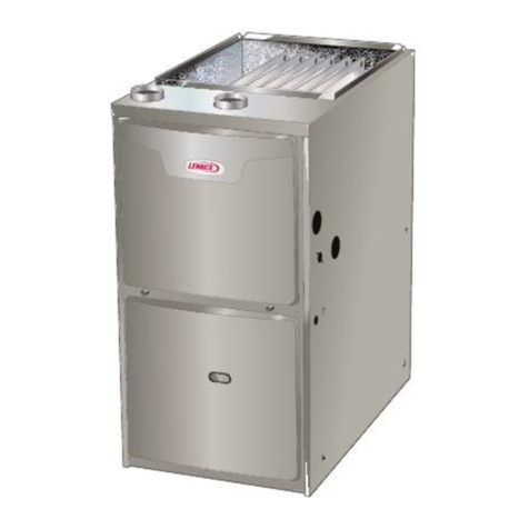
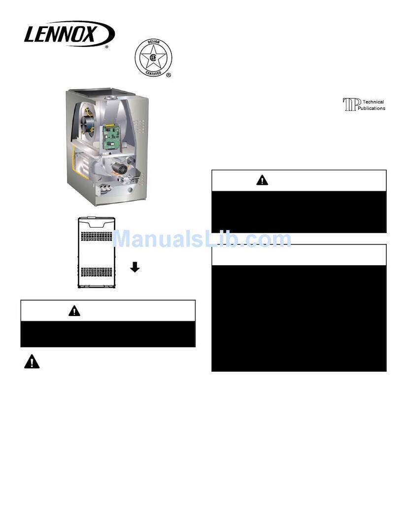
Lennox EL195UHE Elite Series User manual

Lennox

Lennox EL195UHE Elite Series User manual

Lennox ML193DF User manual

Lennox

Lennox ML193DF User manual

Lennox SLP98UHV SERIES User manual

Lennox

Lennox SLP98UHV SERIES User manual

Lennox G51 User manual

Lennox

Lennox G51 User manual
Lennox EL195UH040NE36B User manual

Lennox

Lennox EL195UH040NE36B User manual

Lennox Allied Air A93UH1E User manual

Lennox

Lennox Allied Air A93UH1E User manual

Lennox EL297UH045XV36B Installation and operation manual

Lennox

Lennox EL297UH045XV36B Installation and operation manual

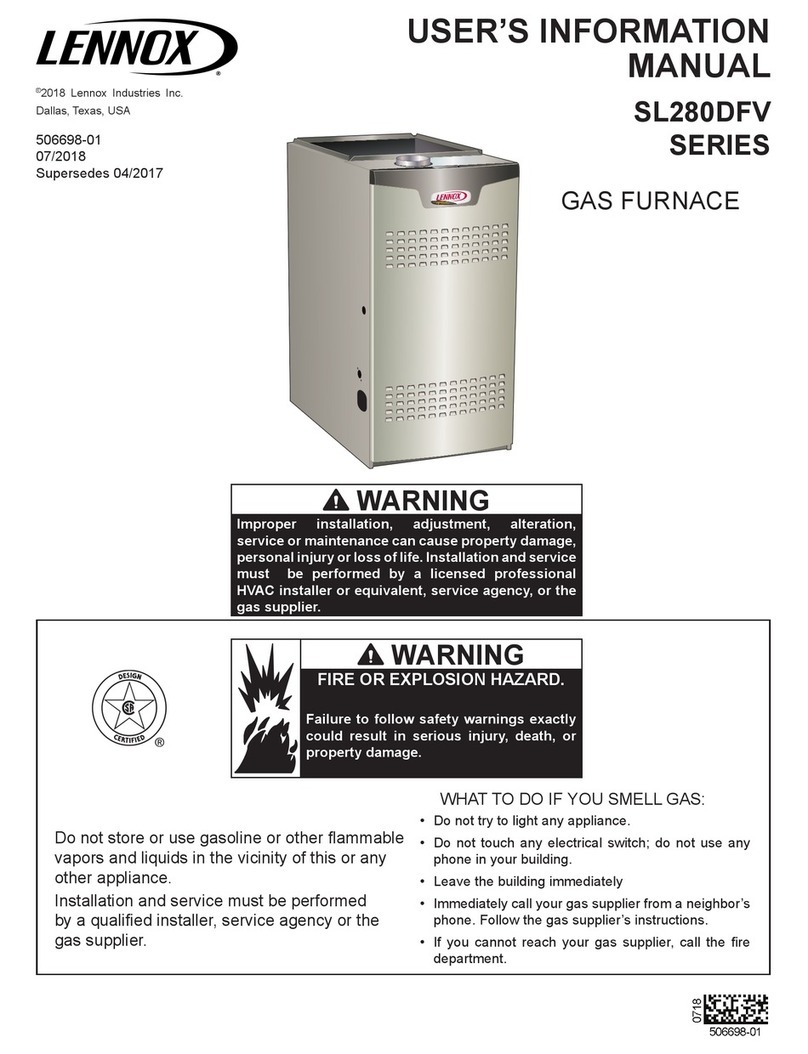
Lennox SL280DFV Installation and operation manual

Lennox

Lennox SL280DFV Installation and operation manual

Lennox G21Q Series Guide

Lennox

Lennox G21Q Series Guide

Lennox O24 series Technical manual

Lennox

Lennox O24 series Technical manual

Lennox ML195UH User manual

Lennox

Lennox ML195UH User manual

Lennox EL280DF070E36A Installation and operation manual

Lennox

Lennox EL280DF070E36A Installation and operation manual

Lennox ML180UH SERIES User manual

Lennox

Lennox ML180UH SERIES User manual

Lennox SLP98UHV SERIES Guide

Lennox

Lennox SLP98UHV SERIES Guide

Lennox G40DF Series Guide

Lennox

Lennox G40DF Series Guide

Lennox OF23Q3/4-105 User manual

Lennox

Lennox OF23Q3/4-105 User manual

Lennox O23 User manual

Lennox

Lennox O23 User manual

Lennox G61MPV Series User manual

Lennox

Lennox G61MPV Series User manual

Lennox O23 User manual

Lennox

Lennox O23 User manual

Lennox EL195DF SERIES User manual

Lennox

Lennox EL195DF SERIES User manual

Lennox SLP98DF090XV60C User manual

Lennox

Lennox SLP98DF090XV60C User manual

Lennox HCF RTL G 17 Guide

Lennox

Lennox HCF RTL G 17 Guide

Lennox ML193DF User manual

Lennox

Lennox ML193DF User manual

Lennox G17Q2-50 Installation and operation manual

Lennox

Lennox G17Q2-50 Installation and operation manual

Popular Furnace manuals by other brands

Unitary products group AHV8 UH installation manual

Unitary products group

Unitary products group AHV8 UH installation manual

VERDER CARBOLITE GERO RHF 14/8 Installation, operation and maintenance instructions

VERDER

VERDER CARBOLITE GERO RHF 14/8 Installation, operation and maintenance instructions

Tempstar B Series Service and technical support manual

Tempstar

Tempstar B Series Service and technical support manual

Carrier Performance 59SP5A Installation, start-up, operating and service and maintenance instructions

Carrier

Carrier Performance 59SP5A Installation, start-up, operating and service and maintenance instructions

Armstrong EG7H SERIES Installation and maintenance instructions

Armstrong

Armstrong EG7H SERIES Installation and maintenance instructions

Payne PG92ESA Installation, start-up, operating and service and maintenance instructions

Payne

Payne PG92ESA Installation, start-up, operating and service and maintenance instructions

NANOE Zetasinter Operation manual

NANOE

NANOE Zetasinter Operation manual

SUPREME FEM10-M2301CM-A Installation instructions and homeowner's manual

SUPREME

SUPREME FEM10-M2301CM-A Installation instructions and homeowner's manual

Johnson Controls TM9T User's information manual

Johnson Controls

Johnson Controls TM9T User's information manual

Fluke 9118A user manual

Fluke

Fluke 9118A user manual

Intertherm M7RL Series user manual

Intertherm

Intertherm M7RL Series user manual

HDG Pelletmaster 15 Operation manual

HDG

HDG Pelletmaster 15 Operation manual

Nortek MG2S Series installation instructions

Nortek

Nortek MG2S Series installation instructions

VERDER CARBOLITE GERO ABF 8/28 Installation, operation and maintenance instructions

VERDER

VERDER CARBOLITE GERO ABF 8/28 Installation, operation and maintenance instructions

Goodman GMV9 Installation & operating instructions

Goodman

Goodman GMV9 Installation & operating instructions

SUPREME SUP10-M2301C Installation instructions and homeowner's manual

SUPREME

SUPREME SUP10-M2301C Installation instructions and homeowner's manual

Dettson AMT400B34-SM1PMA Installation instructions and homeowner's manual

Dettson

Dettson AMT400B34-SM1PMA Installation instructions and homeowner's manual

Evcon DGD 60 MBH installation instructions

Evcon

Evcon DGD 60 MBH installation instructions

manuals.online logo
manuals.online logoBrands
  • About & Mission
  • Contact us
  • Privacy Policy
  • Terms and Conditions

Copyright 2025 Manuals.Online. All Rights Reserved.

3DJH 
*+5
6(5,(6
£
PRODUCT LITERATURE
¤
1997 Lennox Industries Inc.
/LWKR 86$
0

6XSHUVHGHV 0
:+$7 72 '2 ,) <28 60(// *$6
,I WKH LQIRUPDWLRQ LQ WKLV PDQXDO LV QRW
IROORZHG H[DFWO\ D ILUH RU H[SORVLRQ
PD\ UHVXOW FDXVLQJ SURSHUW\ GDPDJH
SHUVRQDO LQMXU\ RU ORVV RI OLIH
:$51,1*
'R QRW VWRUH RU XVH JDVROLQH RU RWKHU
IODPPDEOH YDSRUV DQG OLTXLGV LQ WKH
YLFLQLW\ RI WKLV RU DQ\ RWKHU DSSOLDQFH
,QVWDOODWLRQ DQG VHUYLFH PXVW EH SHU
IRUPHG E\ D TXDOLILHG LQVWDOOHU VHUYLFH
DJHQF\ RU WKH JDV VXSSOLHU
-'R QRW WU\ WR OLJKW DQ\ DSSOLDQFH
-'R QRW WRXFK DQ\ HOHFWULFDO VZLWFK GR QRW
XVH DQ\ SKRQH LQ \RXU EXLOGLQJ
-,PPHGLDWHO\ FDOO \RXU JDV VXSSOLHU IURP D
QHLJKERUV SKRQH )ROORZ WKH JDV VXSSOLHUV
LQVWUXFWLRQV
-,I \RX FDQQRW UHDFK \RXU JDV VXSSOLHU FDOO
WKH ILUH GHSDUWPHQW
'DOODV 7H[DV
-([WLQJXLVK DQ\ RSHQ IODPHV
*$6 )851$&(
£
3DJH 
*+5 3$576 ,'(17,),&$7,21 'RZQIORZ $SSOLFDWLRQ 6KRZQ
DuralokPlus
TM
HEAT EXCHANGER
ASSEMBLY
BURNER
BOX
CABINET
CONDENSATE TRAP
CONNECTION
COMBUSTION AIR PROVING
(PRESSURE) SWITCH
EXHAUST PIPE
CONNECTION
BLOWER MOTOR
HEATING ACCESS
PANEL
BURNERS
INTEGRATED
IGNITION/BLOWER
CONTROL
FRESH AIR INTAKE
CONNECTION
CONTROL BOX
GAS
VALVE
COMBUSTION AIR
BLOWER
BLOWER ACCESS
DOOR
DOOR INTERLOCK
SWITCH
TOP CAP
FLAME SIGHT
GLASS
FILTER
FIGURE
1
WARNING
Product contains fiberglass wool.
Disturbing the insulation in this product during
installation, maintenance, or repair will expose
you to fiberglass wool. Breathing this may cause
lung cancer. (Fiberglass wool is known to the
State of California to cause cancer.)
Fiberglass wool may also cause respiratory, skin,
and eye irritation.
To reduce exposure to this substance or for further
information, consult material safety data sheets
available from address shown below, or contact
your supervisor.
Lennox Industries Inc.
P.O. Box 799900
Dallas, TX 75379--9900
,03257$17 ',5(&7,216
1-- Keep the furnace area clear and free of combus-
tible material, gasoline, and other flammable va-
pors and liquids. If installed in an insulated area,
furnace must be kept free ofinsulating material. In-
sulating material may be combustible.
2-- DO NOT obstruct air flow to unit. Unit must re-
ceive an unobstructed flow of combustion and
ventilating air.
3-- DO NOT store chlorine or fluorine products near
unit or introduce these products into the combus-
tion air. These products can cause furnace corro-
sion.
WARNING
If overheating occurs or if gas supply fails to shut
off, shut off the manual gas valve to the appliance
before shutting off electrical supply.
WARNING
Do not use this furnace if any part has been under-
water. Immediately call a qualified service techni-
cian to inspect the furnace and to replace any part
of the control system and any gas control which
has been under water.
CAUTION
Before attempting to perform any service or main-
tenance, turn the electrical power to unit OFF at
disconnect switch.
3DJH 
IMPORTANT
Any additions, changes, or conversions required
in order for the appliance to satisfactorily meet the
application needs must be made by a Lennox ser-
vice technician using factory specified and ap-
proved parts.
/,*+7,1* ,1)250$7,21 $1' 23(5$7,21
:$51,1*
,I \RX GR QRW IROORZ WKHVH LQVWUXFWLRQV H[DFWO\ D ILUH
RU H[SORVLRQ PD\ UHVXOW FDXVLQJ SURSHUW\ GDPDJH
SHUVRQDO LQMXU\ RU ORVV RI OLIH
BEFORE LIGHTING smell all around the appliance area
for gas. Be sure to smell next to the floor because some
gas is heavier than air and will settle on the floor.
Unit may be equipped with either a gas control knob or
lever. Use only your handto push in or turn thegas con-
trol knob or move the gas control lever. Never use
tools. If the knob will not push in or turn or if lever will
not move by hand, do not try to repair it, call a qualified
service technician. Force or attempted repair may re-
sult in a fire or explosion.
To place GHR26 furnace into operation:
GHR26 units are equipped with a SureLight ignition sys-
tem. Do not attempt to manually light burners on these
furnaces. Each time thermostat calls for heat, the burners
will be automatically lit. The ignitor does not get hot
when there is no call for heat on units with SureLight igni-
tion system.
Gas Valve Operation (Figure3)
1--
STOP
! Read the safety information at the begin-
ning of this section.
2-- Set thermostat to lowest setting. See figure 2.
7+(502
67$76
),*85( 
3-- Turn off all electrical power to appliance.
4-- This appliance is equipped with an ignition device
which automatically lights the burners. Do
not
try
to light by hand.
5-- Remove unit access panel.
6-- On Honeywell VR8205 gas valves, turn knob on
gas valve clockwise to
OFF
. For White Rodg-
ers 36E gas valves, move switch to
OFF
.Donot
force. See figure 3.
21
2))
HONEYWELL VR8205 SERIES GAS VALVE
GAS VALVE SHOWN IN OFF POSITION
WHITE RODGERS 36E GAS VALVE
),*85( 
GAS VALVE SHOWN IN OFF POSITION
7-- Wait five (5) minutes to clear out any gas. If you
then smell gas,
STOP
! Immediately call your gas
supplier fromaneighbors phone.Follow thegas
suppliers instructions. If you do notsmell gas go
to next step.
8-- For Honeywell VR8205 gas valves, turn knob on
gas valve counterclockwise to
ON
. For White
Rodgers 36E gas valves, move switch to
ON
.Do
not force.
9-- Replace unit access panel.
10-- Turn on all electrical power to unit.
11-- Set thermostat to desired setting.
NOTE--When unit is first started, steps 1 through 11
may need to be repeated to purge air from pilot line.
12-- If the appliance still will not operate, follow the
instructions To Turn Off Gas To Unit and call
your service technician or gas supplier.
To Turn Off Gas To Unit
1-- Set thermostat to lowest setting.
2-- Turn off all electrical power to unit if service is to be
performed.
3-- Remove unit access panel.
4-- For Honeywell VR8205 gas valves, turn knob on
gas valve counterclockwise to
ON
. For White
Rodgers 36E gas valves, move switch to
ON
.Do
not force.
5-- Replace unit access panel.
3DJH 
),/7(5
6
A filter must be in place anytime the unit is in opera-
tion. The filter may be located in the unit or installed
in a return air grille. Ask your dealer to show you the
filter location. The filtershould be inspected monthly
and cleaned when necessary to assure proper fur-
nace operation.
FiltersusedinsidetheGHR26series unitareavailable
from Lennox and must be ordered separately. These
foam filters may be cleaned for reuse. If replacement
is necessary, order Lennox part no. 31J81 for 14 X 25
inch filter for GHR26Q2--50 and --75 and P--8--7831 for
20 X 25 inch filter for all sizes of GHR26--100 and --125
units. See figure 4 for removing filter from unit. Use
the following procedure to clean filter.
),*85( 
Press up on side filter
clip to release filter
(One on each side of
cabinet)
FILTER
CABINET
FILTER
CLIP
BACK FILTER CLIP
FILTER
SIDE FILTER
CLIP DETAIL
CABINET
FILTER
CLIP
Cleaning Filter
1-- Turn off electric power to furnace.
2-- Remove blower access panel.
3-- Remove filter by pressing side filter clips and pull-
ing filter up and out.
4-- Clean filter with cold water and a mild soap. Direct
water through filter in the opposite direction of air
flow. Remove all soap residue
5-- Allow filter to drythen spray with filterhandicoater
(P--8--5069), available from your Lennox dealer,
prior to reinstallation.
6-- Replace filter in blower compartment under rear
filter clip. Press on filter sides. Filter clips flex al-
lowing filter to snap into place.
7-- Replace blower access panel.
:$51,1*
%ORZHU GRRU PXVW EH VHFXUHO\ LQ SODFH ZKHQ EORZ
HU DQG EXUQHUV DUH RSHUDWLQJ *DV IXPHV ZKLFK
FRXOG FRQWDLQ FDUERQ PRQR[LGH FDQ EH GUDZQ LQWR
OLYLQJ VSDFH UHVXOWLQJ LQ SHUVRQDO LQMXU\ RU GHDWK
6($621$/ ,163(&7,216
A
qualified service technician should inspect the com-
plete system each season (heating and cooling). The
following maintenance procedures should be con-
ducted by a qualified service technician.
Do not at-
tempt to service the unit in any way.
During a seasonal check the service technician will in-
spect the indoor blower, the pilot and burner flames
along with the venting system.
Venting System
Annually (before heating season) inspect furnace
venting system, heat exchanger, burners and pilot
forcorrosion,deterioration,ordepositsofdebris.Re-
move any obstructions.
Inspect furnace venting system to make sure it is in
place, physically sound, and without holes or block-
age. Vent connector must be in correct position,
sloped upward and be physically sound without holes.
Inspect furnace return air duct connection to ensure
duct is sealed to the furnace and terminates outside the
space containing the furnace.
Inspect the physical support of the furnace to guaran-
tee that it is sound without sagging, cracks or gaps
around base and it maintains seal between base and
support.
Inspect and clean the condensate traps and drain.
Blower
Check and clean blower wheel for any debris. Blower
motor is pre--lubricated for extended bearing life. No
further lubrication is needed.
Burner Flame
&$87,21
8VLQJ IODPH VLJKW JODVV FKHFN EXUQHU IODPH SH
ULRGLFDOO\ WR HQVXUH SURSHU RSHUDWLRQ
Set thermostat to call for heat. Allow unit to operate for
a few minutes to establish normal burning conditions.
Check burner flame by observation. Flame should be
predominantly blue in color and strong in appearance.
Contact your Lennox dealer for a periodic unit inspec-
tion by a qualified service technician.
6(59,&( 5(0,1'(5
&DOO \RXU /HQQR[ VHUYLFH WHFKQLFLDQ LI XQLW LV LQRSHUDWLYH
%HIRUH FDOOLQJ DOZD\V FKHFN WKH IROORZLQJ WR EH VXUH VHU
YLFH LV UHTXLUHG
1-- Check that electrical disconnect switches are
ON.
2-- Check room thermostat for proper setting.
3-- Replace any blown fuses or reset circuit breakers.
4-- Gas valve should be
ON
.
5-- Air filter should not be plugged limiting air flow.
6-- Is gas turned on at meter?
7-- Is manual main shut--off valve open?