Front panel
This comprises indicator lamps, LCD Screen
LED and connectors:
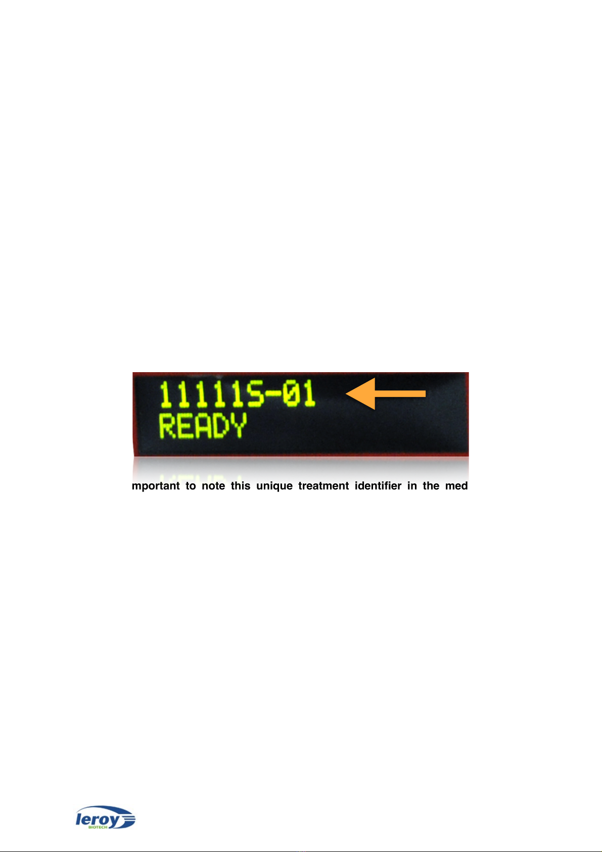
-LCD Screen LED: displays a unique
treatment number as well as information on the
operation of the machine.
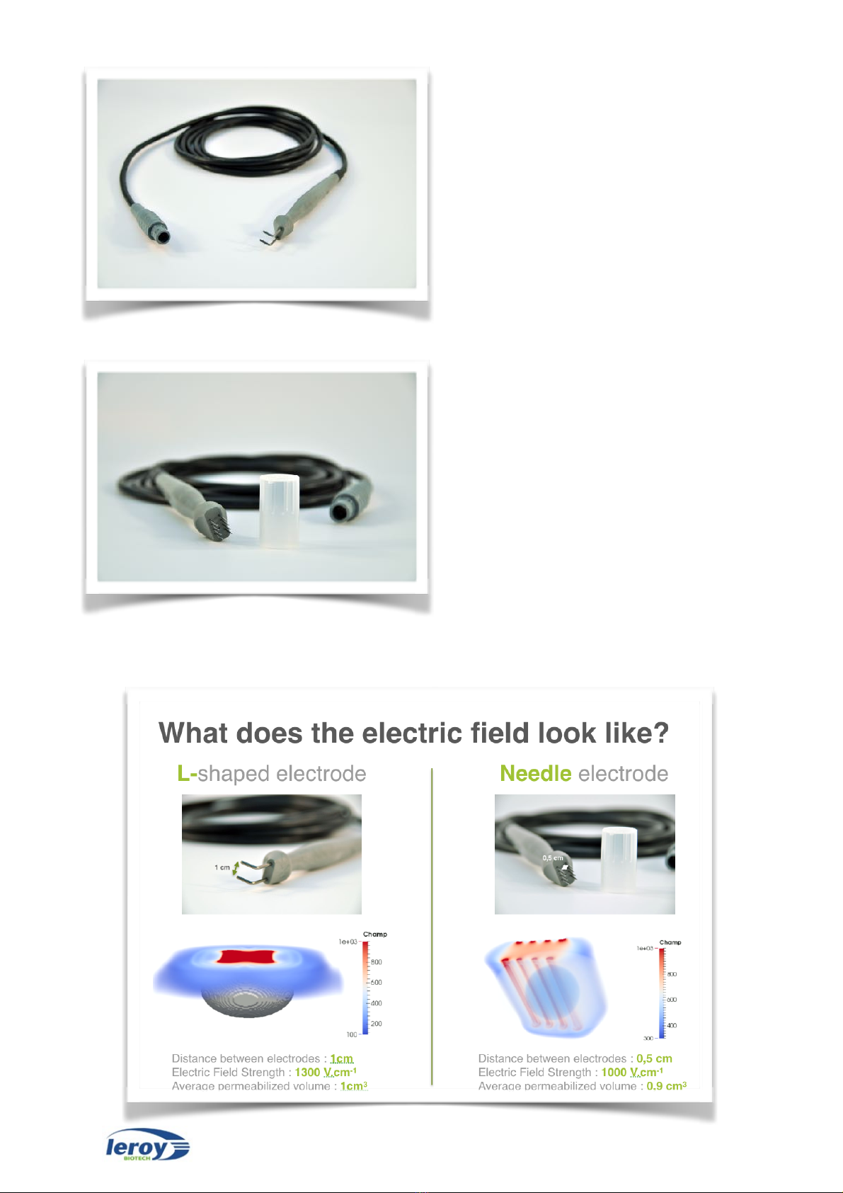
-Electrode connector: connection to the
different kind of electrodes.
-Foot-switch connector: connection to the
double foot-switch.
-ON LED: this is blue, lights up when ON/OFF switch of the device is ON (I).
-CHARGE LED: this is orange, lights up after the foot-switch [1 PULSE] have been pressed.
Note: a single "beep" is heard parallel to the press of the foot-switch [1 PULSE].
-ACTIVE LED: this is green, lights up when electrical pulses have been fully transmitted after
pressing the foot-switch [1 CHARGE] then [2 PULSE]. Note: a double "beep" is heard parallel
to the press of the foot-switch.
-FAILURE LED: this is red, lights up when the electrical pulses were not able to be delivered
correctly, after pressing the foot-switch [1 CHARGE] then [2 PULSE]. Note that a long "beep"
is heard parallel to the press of the foot-switch.
Rear panel
-ON/OFF switch: Position I: ON.
-Fuse housing: contains the fuses designed
to protect the unit.
-Electrical Plug: connection to the power
source by a standard plug.
-Electrocardiogram connector: connection
to an electrocardiogram. Only when needed.
-USB port: contains the USB key on which
all your treatments are automatically
recorded.
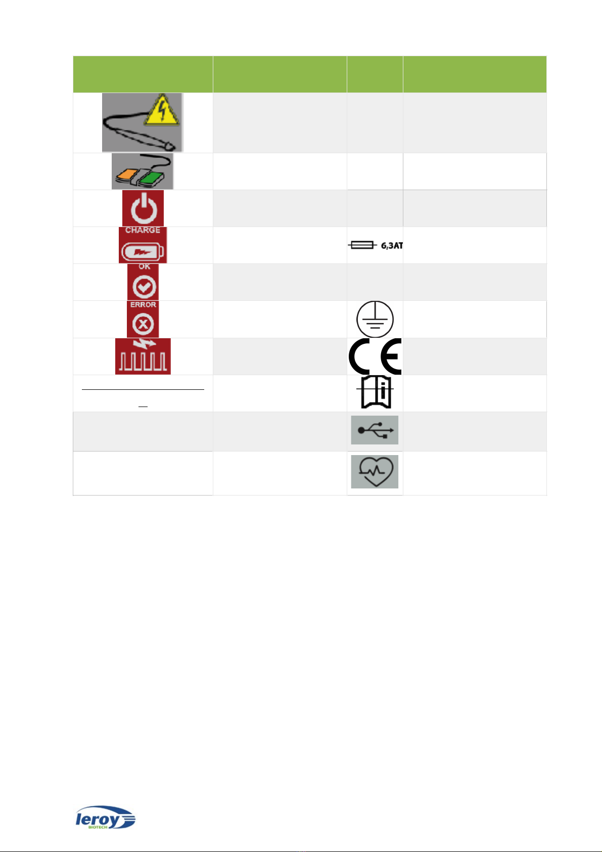
Double foot-switch
-The double foot-switch sends the electrical
pulses. One should successively press the
left pedal [1 CHARGE] then the right pedal [2
PULSE] for sending pulses.
-The left foot-switch [1 CHARGE] allows for
preparation of the device to send pulses
(loading capacitors).
-The right foot-switch [2 PULSE] allows to
send pulses, once the orange indicator lamps
is on.