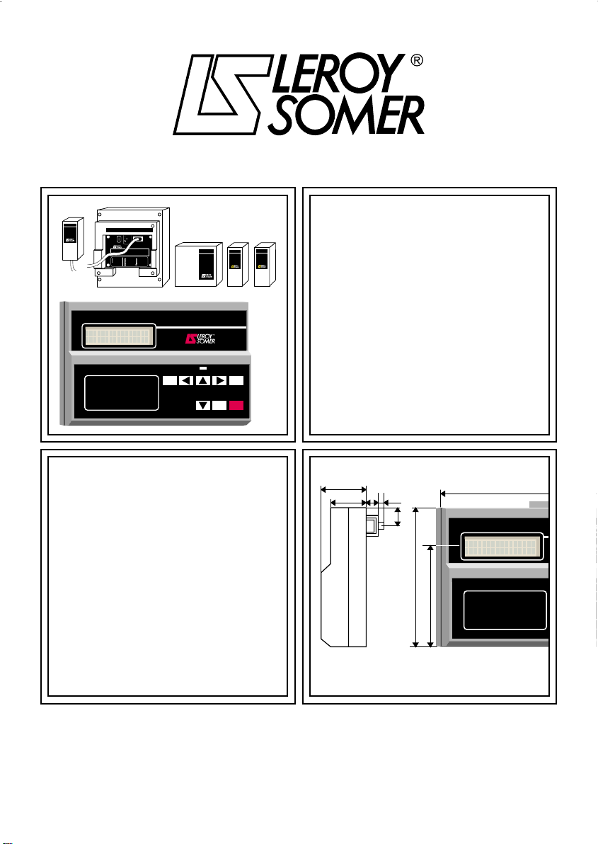
CDC - START
console
6
1
-
GENERAL INFORMATION
1.1 - Operating principle
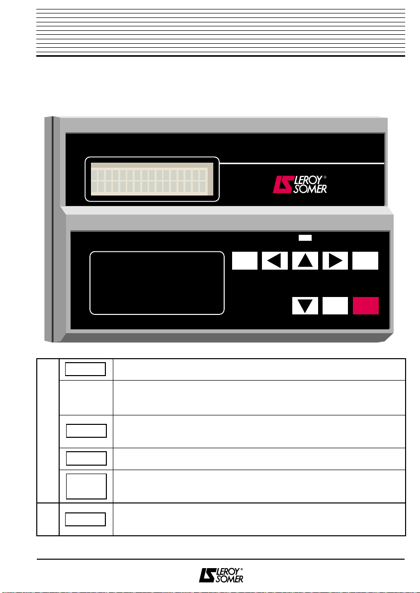
The CDC - START console, which has 8
keys, 1 LED and 1 LCD with 32
characters, is designed for use with
starters in the STV 2313 range.
When connected to the standard model, it
can be used to :
• simplify programming, diagnostics and
display of parameters,
• achieve more precise settings,
• access the following additional functions :
- assigning the K1 relay,
- memorizing a set of parameters,
- limiting the number of starts,
- setting the hysteresis of the over and
underload thresholds,
- setting time delays for tripping at over-
load/underload faults,
- setting the overload/underload alarm
thresholds.
- copying and transferring the parameters
of one STV 2313 to another,
• display data concerning the operation of
the motor :
- absorbed current,
- power consumption,
- power factor,
- number of motor operation hours,
- last 5 faults,
- the current operating phase of the motor.
• set up the other options associated with
the STV 2313 :
- FR - START : DC injection module which
is used for braking, drying or heating the
motor,
- RV - START : speed feedback module
which provides gradual and repeated
starts and deceleration, whatever the load.
- ES - START : inputs/outputs module
which is used to control :
- 2 logic inputs (multiple settings),
- 1 analogue input,
- 2 analogue outputs,
- 2 relay logic outputs,
- 6 PTC sensors.
The parameters linked to the options are
masked and only become visible when the
options are connected.
All parameters relating to a function which
is not validated are masked so as to
simplify programming by only providing
access to active parameters.
Messages are available in 5 languages
(English, French, German, Italian and
Spanish). The language is selected by pro-
gramming.
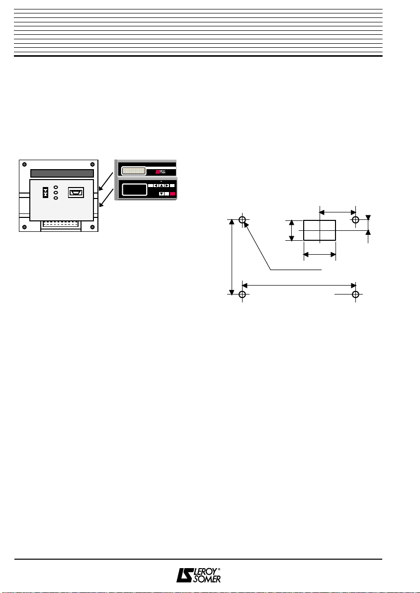
1.2 - General description
Only one programming and copying con-
sole exists. It is called the CDC–START.
1.3 - General characteristics
Power supply : provided by the STV 2313
to which the console is connected.
Display : 2-line digital LCD with 16
characters.
Remote connection : maximum length 5 m.
Page: 6