4 IES-1881 Manual
Supports IEEE802.3/802.3u/802.3ab/802.3z/802.3x. Auto-negotiation:
1000Mbps-full-duplex; 10/100Mbps-full/half-duplex; Auto MDI/MDIX.
100Base-FX: Multi mode SC or ST type, Single mode SC or ST type;
100Base-BX: WDM Single mode SC type.
1000Base-SX/LX: Multi mode SC type, Single mode SC type;
1000Base-BX: WDM Single mode SC type.
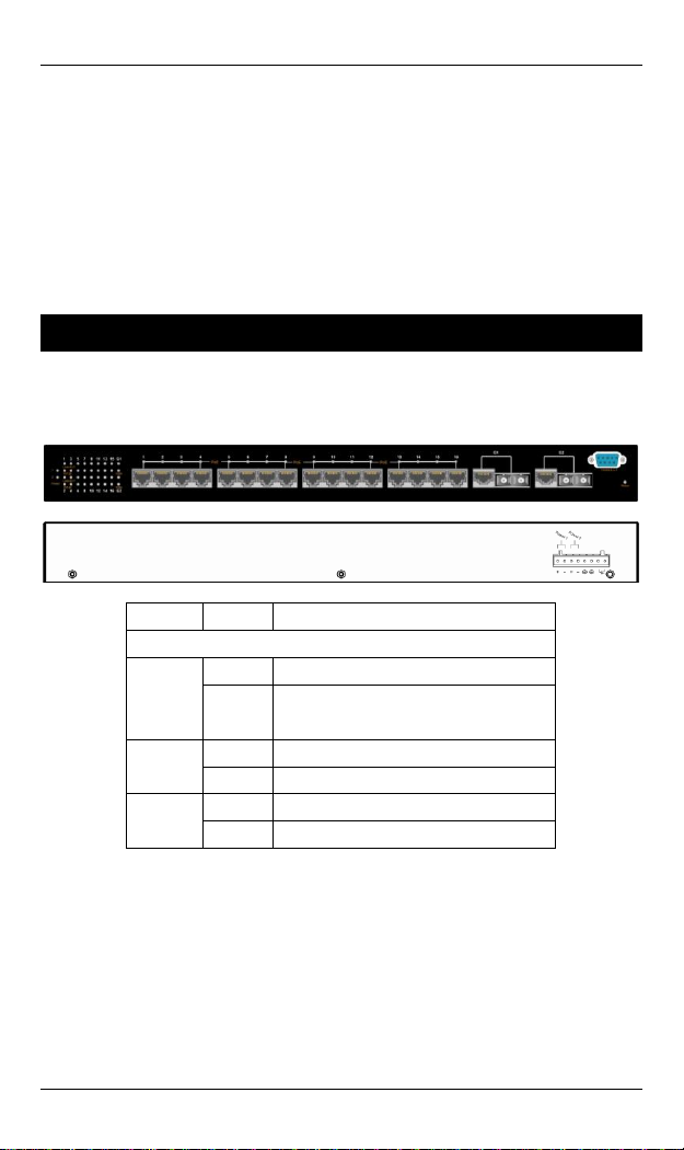
Provides up to two combo Gigabit ports.
Store-and-forward mechanism. Full wire-speed forwarding rate.
Alarms for port and power failure by relay output.
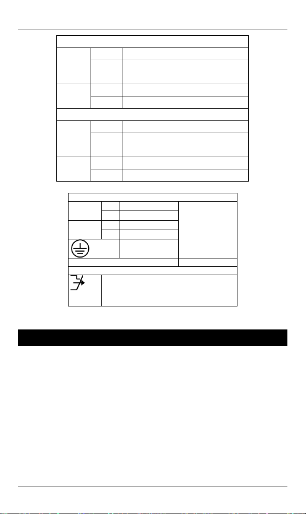
Power Supply: Redundant 52~57VDC Terminal Block power inputs.
Field Wiring Terminal: Use Copper Conductors Only, 60/75℃, 12-24
AWG torque value 7 lb-in.
Operating voltage and Max. current consumption: 0.25A @ 48VDC.
Power consumption: 480W Max. (Full load with PoE), 12W Max.
(Without PoE).
-40℃to 75℃(-40℉to 167℉) operating temperature range. Tested for
functional operation @ -40℃to 85℃(-40℉to 185℉). UL508
Industrial Control Equipment certified Maximum Surrounding Air
Temperature @ 75℃(167℉).
For use in Pollution Degree 2 Environment.
Hardened metal case.
Supports Rack Mounting installation.
<Note> Make sure to readjust RTC Time of this switch to function accurately
after this switch has been powered off for over 72 hours.